Preciseness is the key
In this world of minuaturization, the electronic parts are smaller and smaller. As an human, you can not have the precision of a machine. Instead, you need to be patient and work on your skills to make any movement with preciseness. I am completely new to this field and subject, but I saw and talked to some people that are good on that field. It looks like the hardware is one of the main skill you need to have to create a good electronic board fiable. After that, technically, if the hardware is good, then you can concentrate only on the software. It's logical to eliminate the problem's source. So if you're soldered and your components are good, then half of the job is done. So let's see what I can learn in that new crazy world called electronic. Here is the group assignement documented by Bomi.
Create a programmer and program it
This week, we need to do a programmer. This king of piece will allow you to program your other electronic circut. When you have a board, it doesn't talk the same language as your computer so you will need a middle board that you can push your code in and than this board will translate it and send it to your main board. The brain that we will use on our programmer is call the Attiny 44. You can have plenty of them with different speeds, spaces and possibilities.
To make the programmer, we have 3 main steps to do:
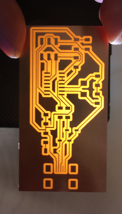
- CNC the circut
- Weld the circut
- Program the circut
How to
1-Create the files to create a circut board
- François sends us a Eagle file that have all the component in it. In Eagle, you can create a schematic of your board and from there generate the final form of the board. The adventage of it is if a component changes or you want to create another shape, you can without changing all of your line
- When the board is created, you want to choose a Gerber file reliated to the type of circut you will do. It is gooing be one side or both side circut for exemple
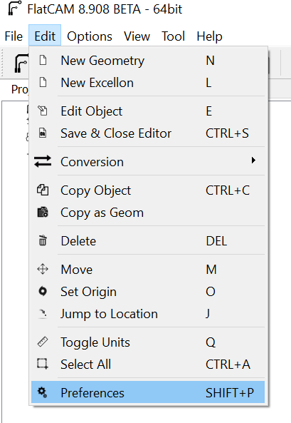
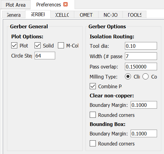
- On FlatCAMthe first thing you need to do is to change your Preferences and in the general section change the unit for mm. Our cnc machine can not work with the Fabmods because of that conversion of the code. Even if we change the code in the program, the gcode generate is not good.
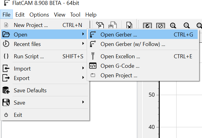
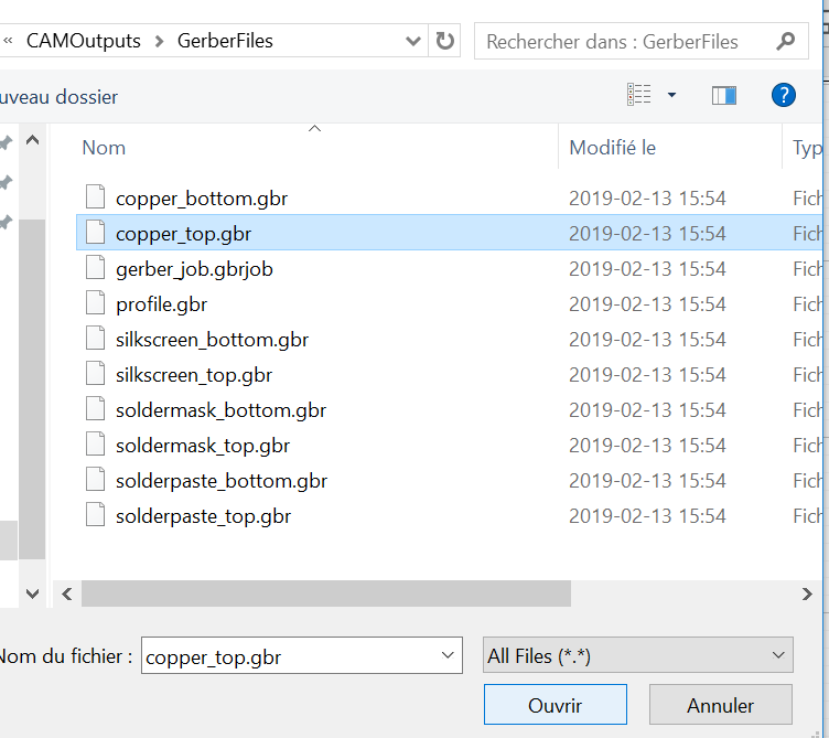
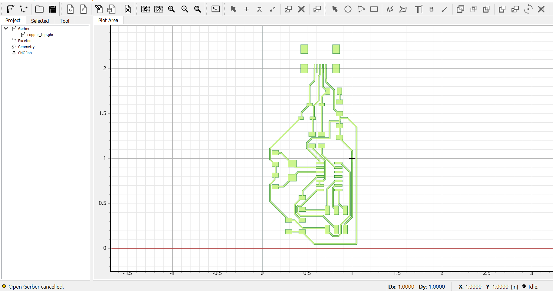
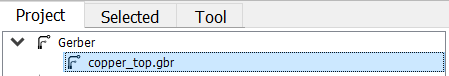
- When your parameters are good, you can open your Gerber file in FlatCAM (choose the copper_top because in eagle you specify the top_copper.
- FlatCAM will generate the trace of your board
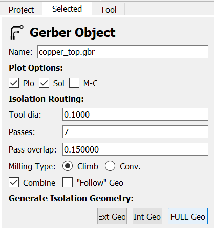
- Double click on your Gerber file copper_top, select Full Geo and enter the good parameter for your machine.
- It will generate you a CNC Job and if you double click on it, you can save the job
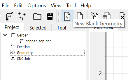
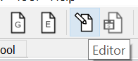
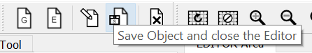
- Create a New Blank Geometry, Editor and draw manualy a shape around the circut. save object and enter the parameter of Geometry Object for your machine
- It will generate you a CNC Job and if you double click on it, you can save the job
- These two file can be saved on a USB and then sent to your machine
Here is the Eagle file

Click on this logo to generate your final form

The final form. You can add here some texte or inscription on your circut

Click on CAM Processor and chose Top Copper (for circut for 1side)

At the end it will create a file like this with all your gerber in

Open FlatCAM and change your preference setting for the tool you will use on your machine
Open your gerber file
You will see something like this
To create a new geometry for your path, click on your Gerber file and select Full Geo)
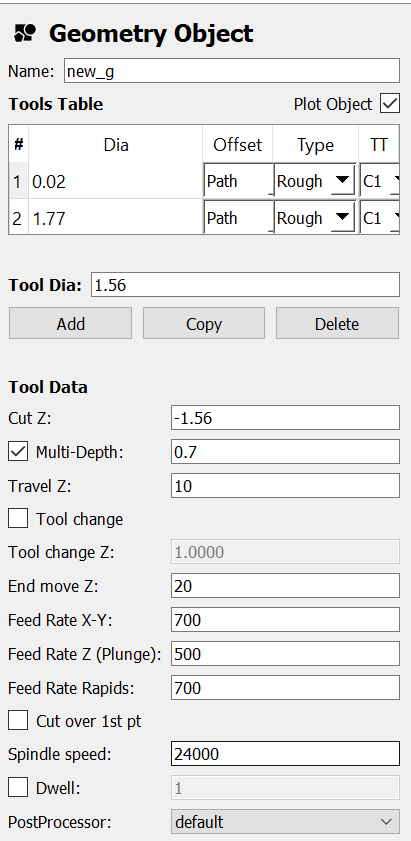
Here are the parameters in Geometry Object for the path
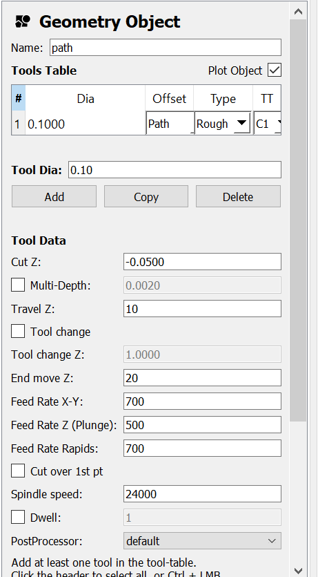
Create a new geometry for your outline of your board, edit it and save it
Here are the parameter in Geometry Object for the path
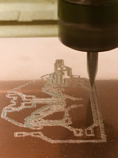
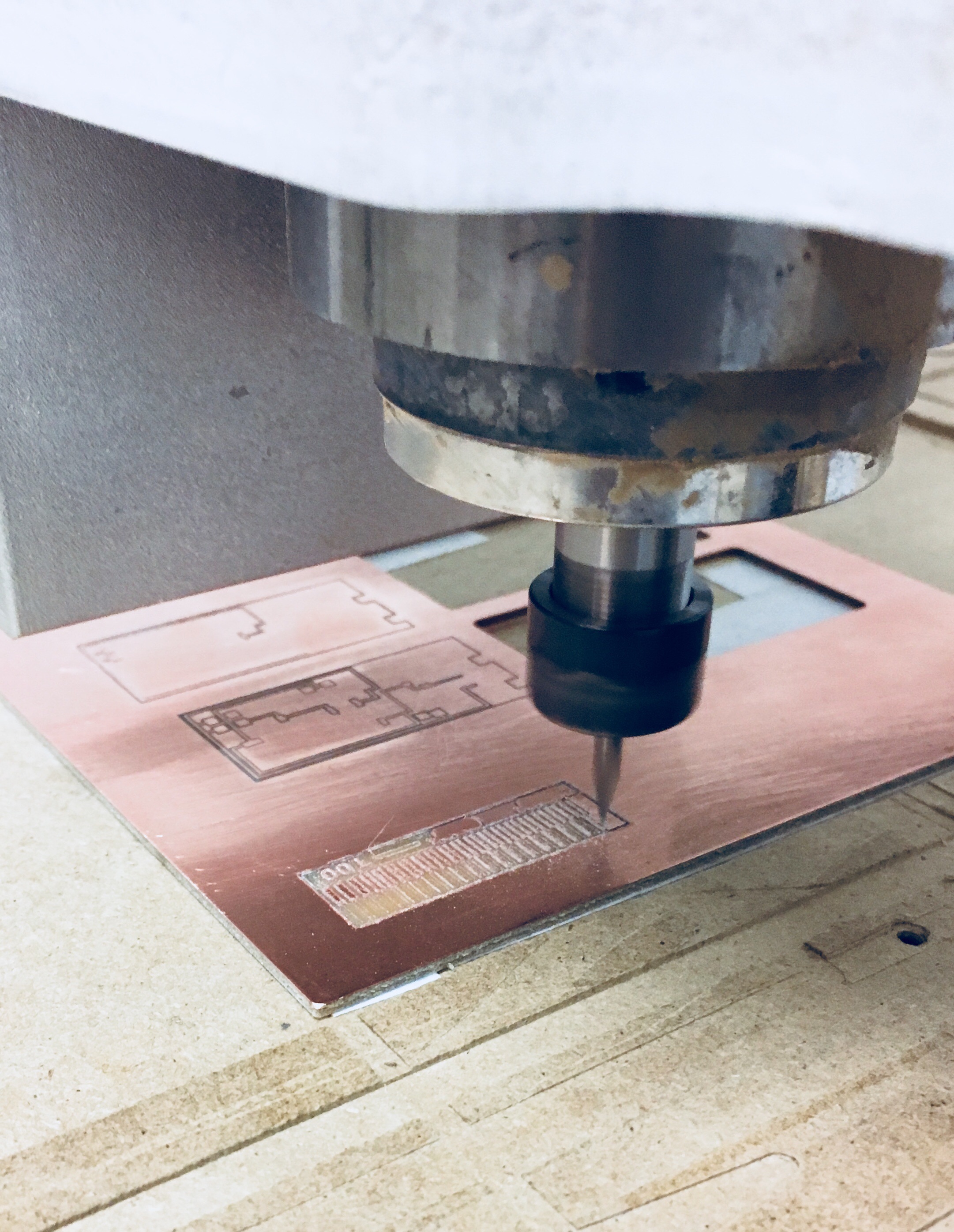
2-Mill and soldered
- Verify the level of the bed where you will mill your circut.
- Put some double side tape under your FR1 plate and push has hard has you can your FR1 plate on the bead to flatted it and make it stick hard. Don't use the double side tape a little bit foamy it will move the plate.
- Install your bits on the cnc machine. The one I use comes from China and they have a flat surface that create a triangle shape. That allows the tips of the bit to be 10mil. The more your bit is in the milling machine, the more it will be stable and the bits will be stiffer, so it have less tandency to break.
- Set the origin of your axes and on the Z axe verify the conductivity between the top of your FR1 and the bit.
- Send your job.
- Sand very lightly your board to clean it with a 400 sand paper. It's only to clean the little copper that is supposed be detached, but is still attach by a tiny piece.
- You are ready to weld everything.
Steps for weldding
- Tape lightly your board to a surface
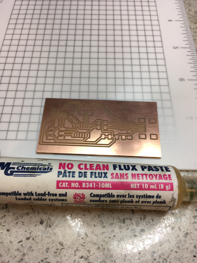
- Apply some flux
- Weld left to right if you are a right handed
- Clean your soldering iron with the tip tinner and a wet sponge
- Apply the tiniest solder wire on the tips of your soldering iron
- Create a fix pad (heat the surface with the iron and apply some solder wire next to it
- Take your component and fix it by heating the pad
- Fix the component in the opposite diagonal
- Weld everything else
- Be very carefull, fix your component and add a little more on top after
- It must be little bubble shinny
- You can verify your work with a microscope and a multimeter
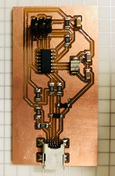
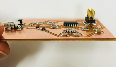
- You can see in the last picture of this section that I soldered a resonator and not a crystal. It was an error. I discovered that a resonator is pretty similar to a crystal, but it capacitance is already combined to electronic part. In that schemetic, the capacitances are outside (so it's a big hint of what you neeeded here) Also a resonator will have 3 pins. It the strip in the middle, it's normaly the ground so you must soldered it at something (second hint, I only have 2 pins..oops) You can see in the first picture of the next section that I changed it.
Mill your pcb
Put some Flux Paste
Start by soldered the usb connector first and than work true the other side
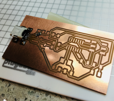
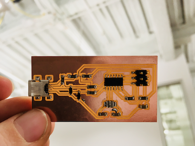
The web adress on the picture before is the ssh adress of the repository on Git Lab
3-Program the board on a Mac OS
- Following the official tutorial from the Fab academy, I downloaded Crosspack AVR,Xcode and the FabISP Firmware for MacOS 10.8.2
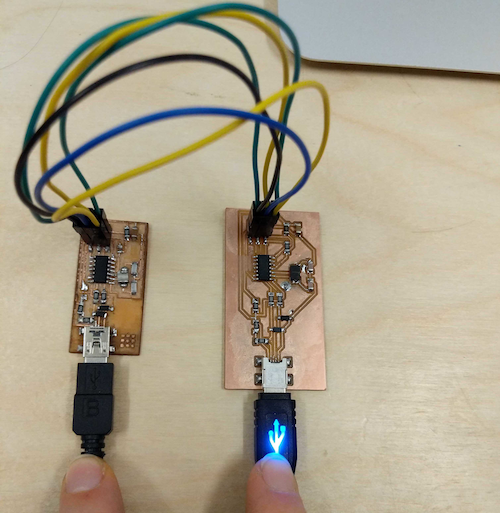
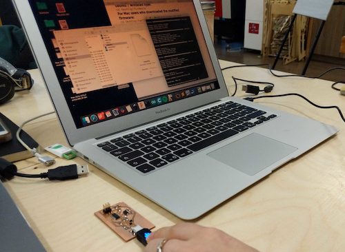
- Connect your board and a programmer board on USB and connect the ISPheader together. I use a FabISP from a year before
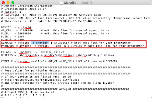
- Open the Makefile with TextEdit and change the # from the code like the turorial says.
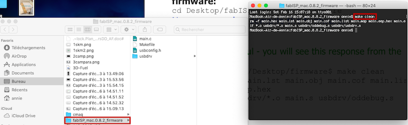
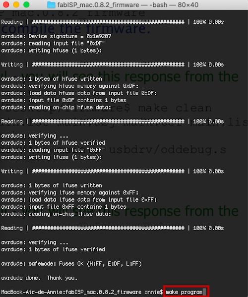
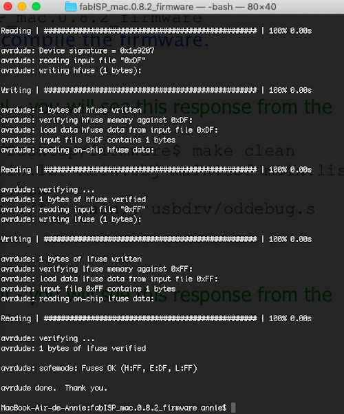
- Open a terminal with the FabISP firmware you download and make this sequence:
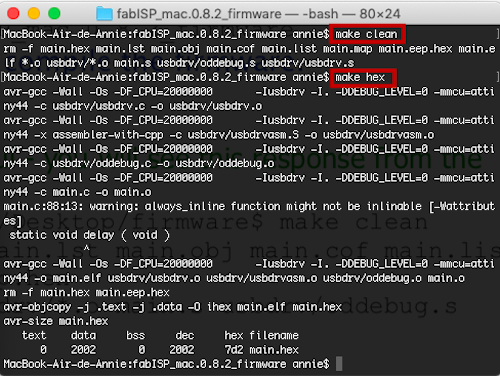
- make clean
- make hex
- make fuse
- make program
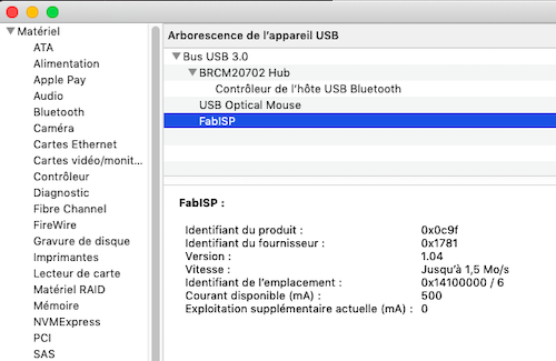
- Boommmm success!!!! First board, first soldering, first programming...I am amazed!
Connecting the programmer and my board
Edit the Makerfile on TexteEdit
Do the secquence
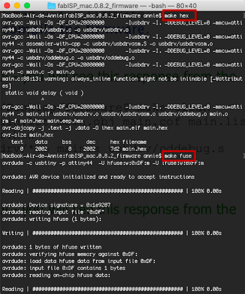
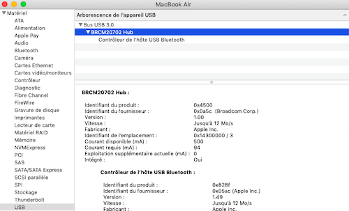
Verify
Group problem
There is a problem. The situation is that everybody in the lab who already made it have their circut done, have their program and everything is looking perfect. When we all verify the usb connection, it is the same surprising silence for everybody. We check a lot of things, but everthing looks perfect. The weirdest thing is that Philippe , made a programmer Attiny 85 that he programed with another programmer, have a different method and he still have the same problem of us. Really spooky.
Solution
It was a problem of component. So, usually on the packaging, it indicates the maximum amount that the component can support. For exemple; RES 499ohms 1/4W. That means it is a resistance that can not have more than 1/4w that pass true it. In the case of the zener diode, we verified in the datasheet, it is the same number that means that it will consume that amount of watt. so you need to install zener diode of 500mw.
Check
The moral of this story
You really need to be calm and in a good mood to weld. Surprisingly, I did really great on the first time and the more I do the more I'm getting good and fast. The tutorial for the programmation was very well explained too and had no problems. I think that in these kind of things I need to let it go a little bit. I can’t control the fact that I don’t know every details of what I am doing, but based on many other examples you can make it work even if you don't master the subject. It's a bit like magic in my head. We put a resistor there...I don’t know why most of the time… for now...but it works...and then you download something that break the fuses and boom we have create a programmer! Let's see if after the fab academy the electronic will still be magical for me. Also, I mill the test board by curiosity of using the fabmodules and to see the limits of the tool I used. I was supprised that the inside and outside lines was not the same, but after all it's logical. Because of the retraction of the tips of the bit witch have a shape of a triangle. The size of the bit is consequently bigger each time you mill in this case. I am glad that I was able to achive that first step in this new field. This week is a succes for me. It's not perfect, but from where I start, it's an happy success. Files
Contact
Annie Ferlatte
ferlatte.annie@gmail.com
Montreal, QC, Canada