Creating movements
The machine that we create is inspired by this DIY claw machine. First, we need to find a purpose to that machine. Then, during a brainstorm, we figured that users have normaly the total control on every machines of the lab and they give you no emotion. It could be interesting that the user can control the machine but sometimes...when the stars are aligned...the machine complete the users movements or do his own movement of his choice. At the end, the goal is to pick not a Teady bear but a fortune cookie in the bottom of the machine. You can go see our group site for further informations on our machine.
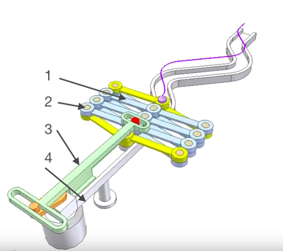
Creating the z axe
My part of that project is creating the z axe and with Bomi the machine design. This week I work around mecanism that extend and retract with a simple servo motor. This will serve also for my final project which will be a similar mecanism to the open and close the wings of a bird.
Step by step
I search on internet the kind of movement that I want and found this video. I will need to build:
- The cross section in laser cutter
- Developp press fit pin in 3D print
- The extention of the motor
- The rail who guides the movement
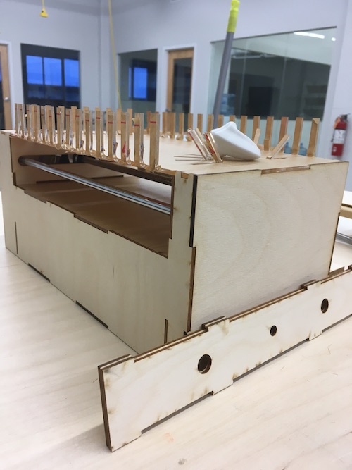
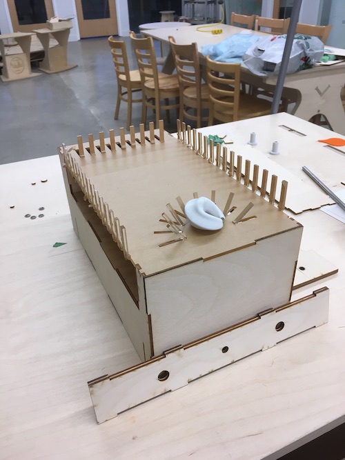
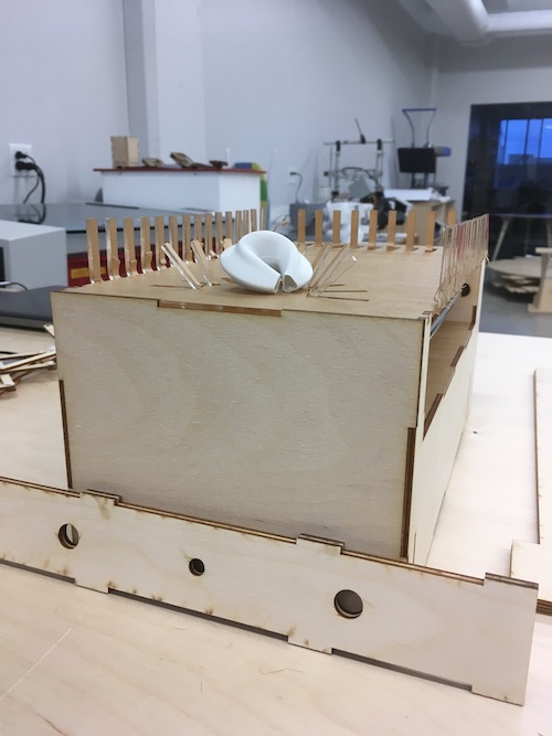
Creating the outside of the machine
Bomi and I plan to design the outside of the machine after the team of Sylvain and Chuma finish the axes X and Y, so they will have as much liberty possible. After seeing their work, we figure that we can make a box to integrate the electronic on the bottom and nothing on the top so it will be minimalistic. We do a sketch of what we want to do, divided the work...and do the work.
How to
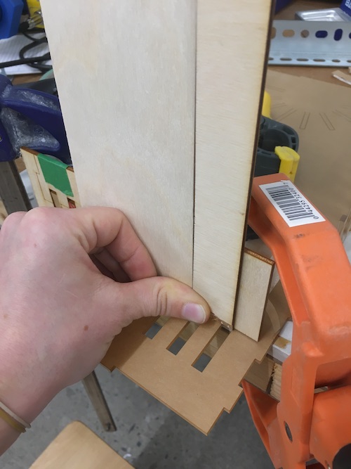
1-The pin
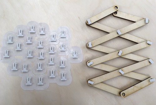
Before doing the cross section, I need to figure how small each end hole can be and this is determined by the press fit pin. This one need to be a little bit flexible, the shape need to limit the friction and it need to be strong enought to support all the forces that he can take
- First I try to validate some thought, can a 3D print be flexible? Can I print a small 90deg surface without support and that will allow the snap fit?...
- On Fusion 360, I draw a slot shape and I Revolve a shape. Better start with bigger.
- On Inkscape I draw a series of holes that I think that can be possible that my piece snap.
- I found the e-NABLE hand and they use a press fit 3D pin much more smaller.
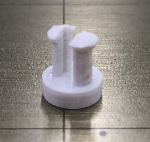
- I analyse it and make my one on Fusion I skip the roud shape for the moment, this model I made can be print laying on the side. I did also different washer to experiment.
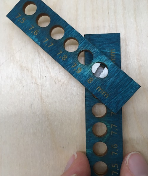
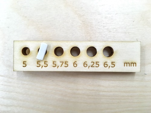
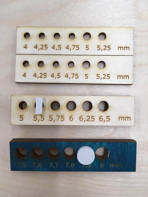
- I did a lot of back and fort for the height of the pin. For two layer of plywood 3mm, my pin is good with a height of 6,5mm. This 0,5mm is a nice tolerance to allow the wood to slide on each other without resistance.
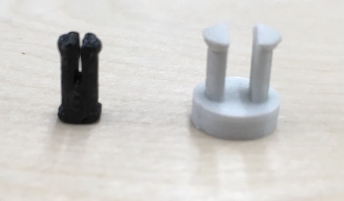
- This last version of pin is much more smaller. It can fit in hole of 5,5mm instead of 7,9mm. The friction aspect is also great, without washer is very fluide.
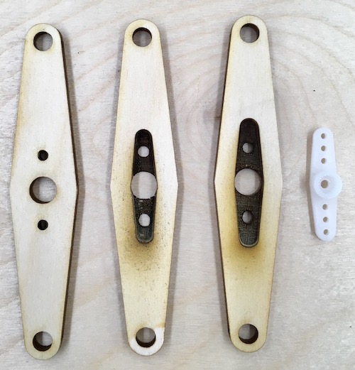
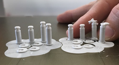
Development pin no.1 with laser cutter test holes boards
Comparision pin no.1 with the pin e-NABLE
Development pin no.2 with experiment washers
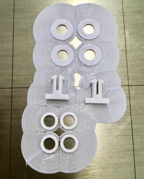
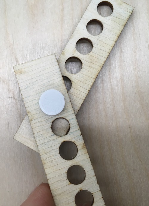
Result of pin no.2 and comparision with pin no.1
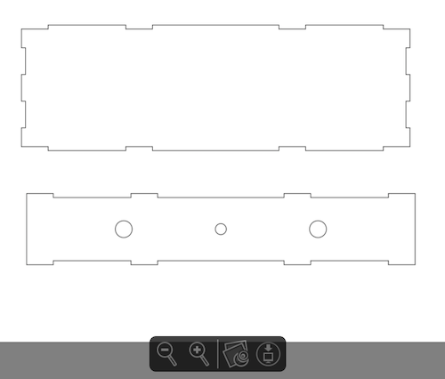
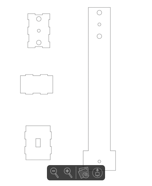
2-Create the cross section, the extention and the rail
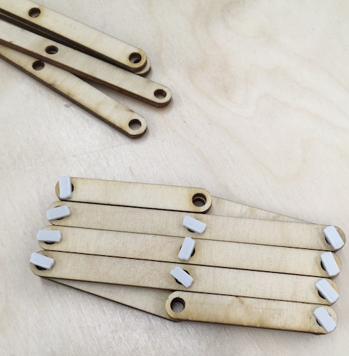
- Based on the result of the first phase, I draw some section of 4in with hole of 5mm (I continue changing a little bit the geometry of the pin no.2 and I make it work with 5mm hole.) I made also 4 pieces of 2in.
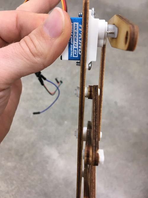
- Back on Fusion I draw the extention of the step motor. It is faster to do it in sketch on fusion and import the DXF on Inkscape. I was then sure of the precision of each elements.
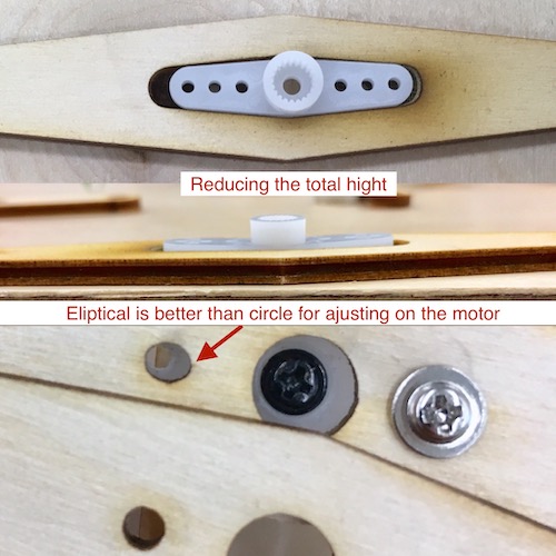
- I engrave also a part to integrate the step motor module. In that way, the total height is reduce. This hight is important fort linking everything in together. To work well it needs to have a great alignment.
- Then the rail and the attachement for the motor was pretty simple on inkscape.
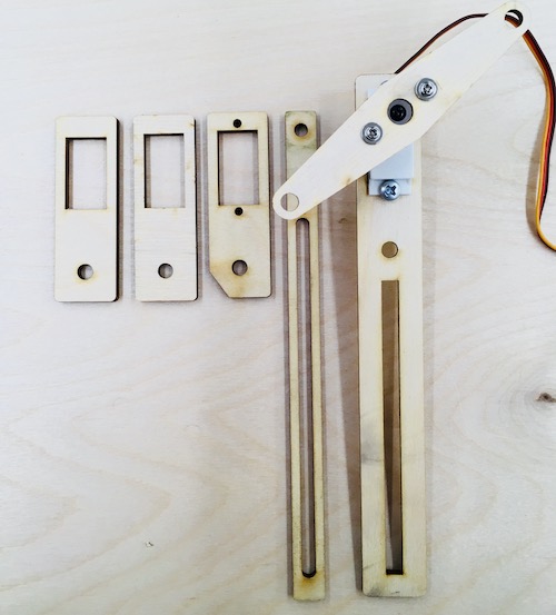
Assembling and testing with the press fit pin
Evolution of the extension of the motor
Evolution of the motor attach and the rail
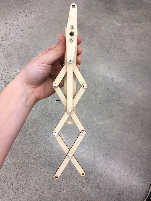
3-Linked everything toghetter
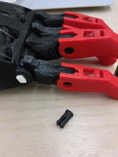
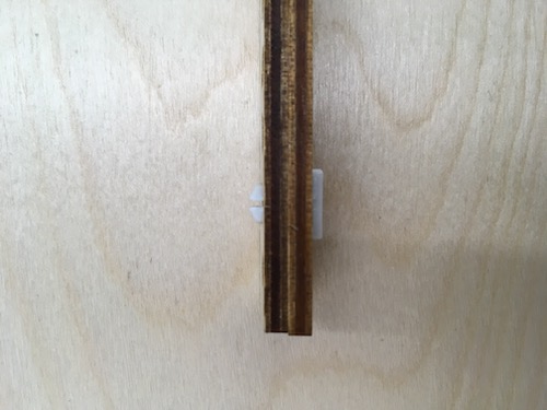
- When I linked everything together, the alignment was a issue and the pin needed to be flatter. Also, when I try manualy to do the movement, some of the press fits pin were poping out so I developped another pin with a smooth circular shape and a secure closing.
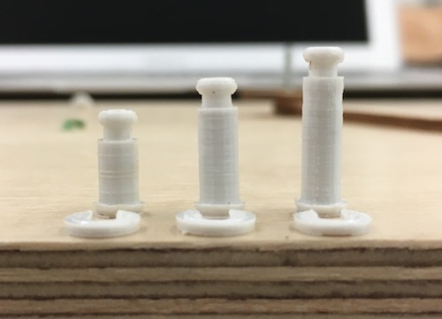
- I did different height of this tubular pin to make a better alignment (see pictures).
- I discovered that every first print of this pin are failing for the longest one. But without changing anything, the second print is always good...I think the machine is not completely warm when it beggin and at the second print it is...but that is a theory.
- To adjust the alignment, I add my previous 3D print washer or a acrylic washer I lasercut
- My final step is to test the step motor with a simple code to see if it was strong enough to move everything.
Flat and secure pin
Assembling
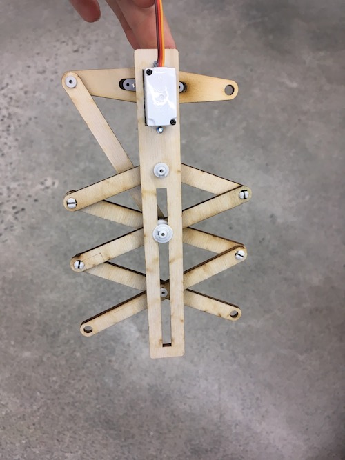
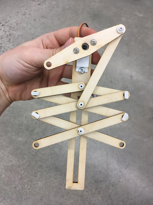
Testing the final motion
4-The rest of the machine
- Mesure every thing that will have a interaction with your design. (power supply, rods, step motors..) Don't forget to add a tolerance for a great fitting
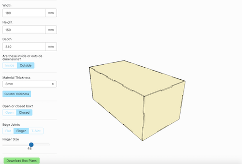
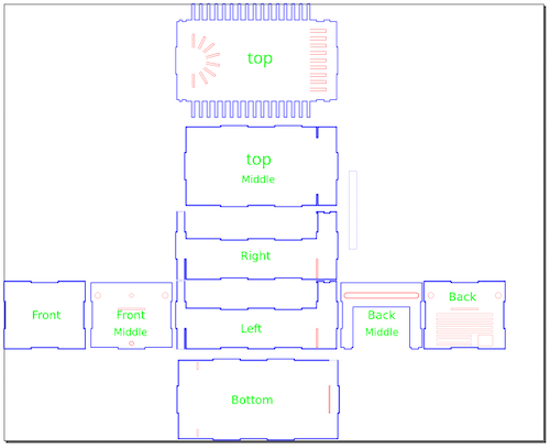
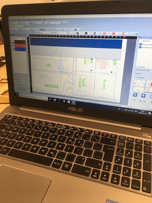
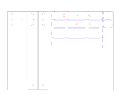
- The thing that we plan to create looks similar to a box so I go on Maker case, a site where you can easily and quickly generate parametric standard box. Enter your dimentions and download the svg or dxf file.
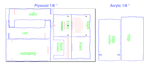
- On Inkscape, I modify the vectors to add holes, modify the fingers, make some pieces longers, etc. I have a very clean visualisation of the final assembly in my head.
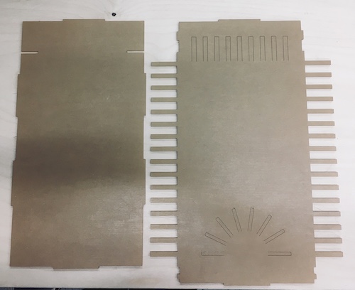
- For the top of the machine, it is supposed to hold fortune cookies so it needs to be like a bowl, so to minimise the assembly and try something new, I draw some unclose line that will (after laser cutter) can be fold with a heat gun. Less glues, less ardwares...less troubles..maybe? We will see.
- In the same mindset, I need to create a specific place that will allow the choosen cookie to land so we can read it. To do so I imagined the shape of a half sun that I can place in the middle front of the machine.
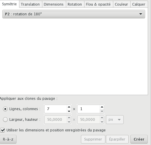
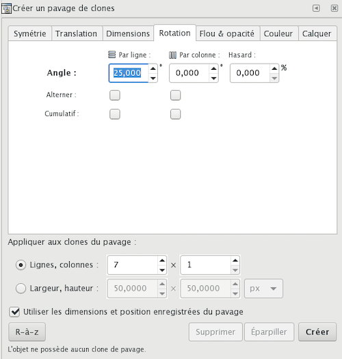
- To draw some open rectangle (sun ray) perfectly align with a half circle is not easy on Inkscape, but I remember the parametric texture I made in week 3- Parametric Design. With the same cloning fonction I could make something great.
Start by making a simple box on Maker Case and export it in .svg
On Inkscape, modify the box. I use the ruler of Inkscape to align every pieces on the same ground to match the hight of the elements. I am from architecture and it was the same method...back in the days to draw on autoCad. You can aline all your elevation than place them place it in the good position around the plan (so here the bottom)It help to figure what goes where.
To complete the top which will be in acylic, I need to design the landing cookie place. Here is how I did to create that half sun. In inkscape I draw a circle and a vertical rectangle on it. It went, exactly like week 3, in clone and create a clone tiles. I select these parameters showed in the picture, the rest was 0. I cut what was in the middle and voilà!.
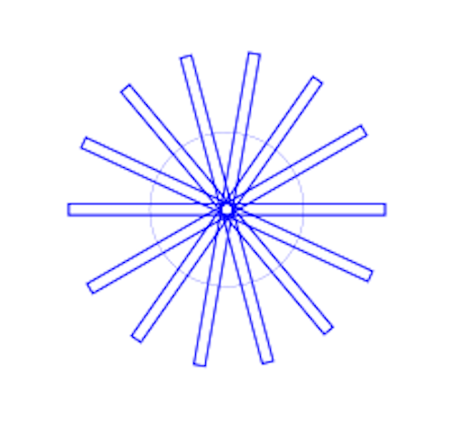
You can see the final result of the drawing here.
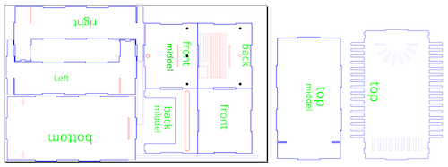
This is a final check, put the right color to the element (here the red will be cut in 1st than the blue). I was thinking to engrave the wood to hold the axes, but when I did it, I put everything in place without glue and the tolerance of the axes was too small so I desided to cut a hole afterall and put the same 3d printing part that Sylvain has done to hold the metal rod. (I base the hole from the pdf drawing from Chuma.)
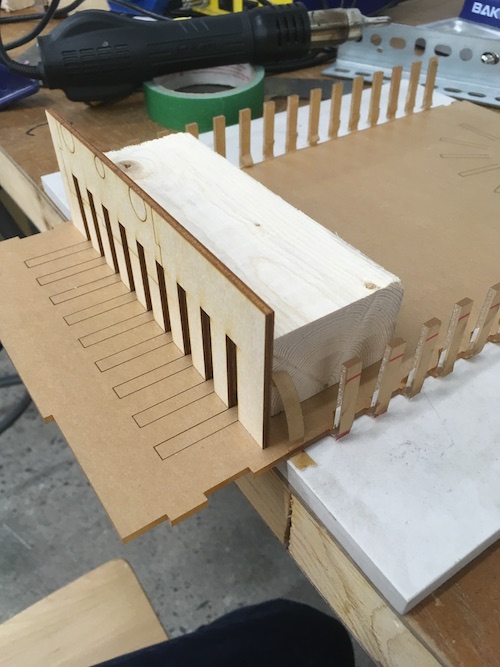
To fold these little rectangles up, I take a wood 2X4 just to create a wall and I start heating the top of the rectangle. I was too impatient so the piece moved just not enought so I bend it and broke it...oops so I tried again being more patient this time and fold it. It did not fold straight so I cut a guide to help me folding straight as you can see. To protect your finger from the heat of the gun I used a piece of wood to fold it and another one with a clamp to hold the pieces until they are cold.
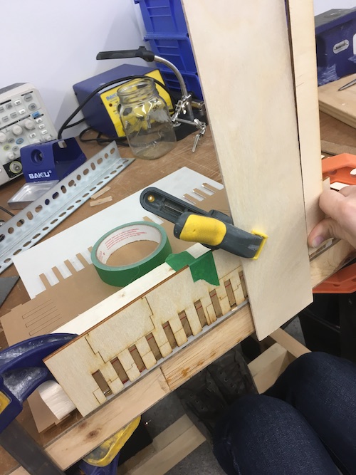
Assemble everything with the axes with no glue to verify if everything is fitting well. I leave the protection paper on the acrylic to protect until the last minute.
Based on the pdf of Chuma I modify its piece to make a fist version of the axes x,y. It's a little smaller to have a bigger tolerance and a lighter look. Doing it tested the flexibility of the material and spot fiew improvement. Sylvain take from there for the axes.
Chuma PDF
Modification on Inkscape I made.
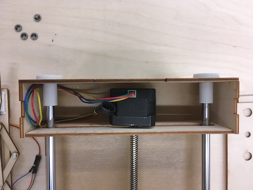
5-Automation of the z axis.
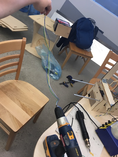
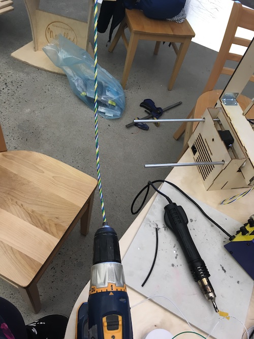
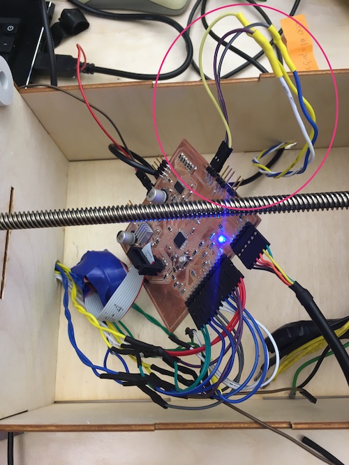
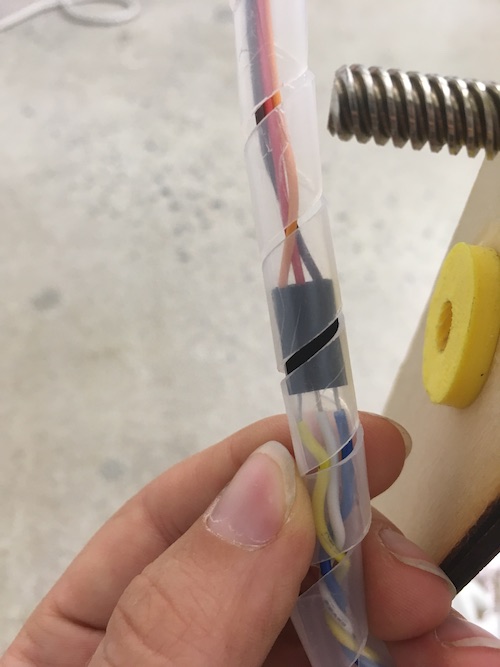
- To finalise the z axis, I needed wire. Francis show me a really nice tips to do so. I take 3 wires of differents colors and plug all of them into a drill, press on...tataaaa it give a wonderfull wire twisted.
- Strip the protection of the wire at the end of it and plug it to your connector. To protect the connections and make a good wire management, I use a twisted wire management tube. So when the machine will move, all the wire will be moving toghetter in this protection sleeve.
- Connect your wire into the board and with. the code test the z axis up and down.
- The Z axis is now automated.
- My biggest learning in that machine working with the groupe is never under estimated the cables management. I already plan some hole in the machine to integrated the cables, but it need much more to do something clean and durable in time. With Francis we put all the heatshrink tubing on everyconnection. and it was longer and messier that we exepted. Next time I will probably incorporate more the cable managment into the design.
- I learn also more about the interconnection of the design, the motor and the circut. We canot change the z servo for something stronger because the board couldn't supported and the claw was much more heavier that we expected. I add a pring to my design to help the servo going up a little bit. and Bomi made the claw lighter using my connector directly.
Create a twisted wire to plug everything.
Connect the servo motor to longer wire
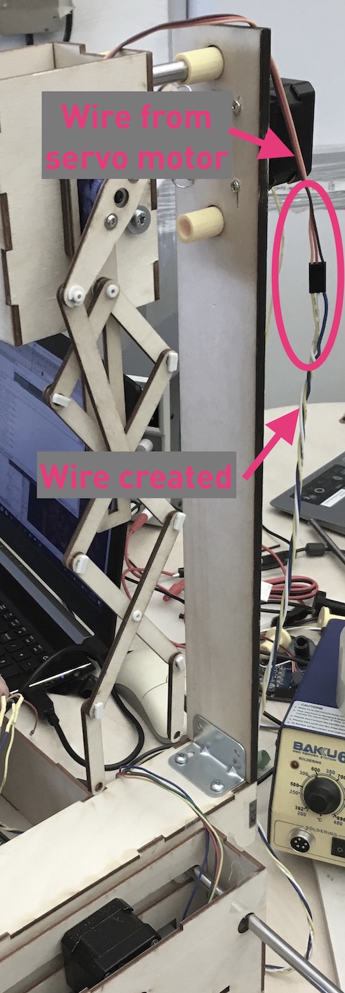
We didn't have anymore connectors so we wire the new twisted wire with femal jumper and add some heatshrink tubing to protect the connection frome the board to prevent shorts.
I twiste a protection sleeve to hold everything toghetter. We add to this same sleeve the other wire from the top of the machine.
Pushing the code and test the z axis.
The moral of this story
I am glad I could test and learn how to bend acrylic and play with the material deformation and it's reaction. A machine fitting is also delicate and it needed more managing than I expected. To assemble the whole machine, you really have understand the building sequence. You can devide in different parts, but a overview of all is needed to link every part together. I think also that the hardest part is in the details of the machine's small parts. For expemple, developping the snapping pin needs a lot more of iteration than the rest of the design. Also, all the details interacting between the part, which screw you will use, which stepper, the size of the wire and where they will be. All these details influence on the good fonctionality of the machine and the sustainabilty of it. Will you keep the machine or not? I really enjoy that week and challenging me on the machine to work fast and in itterations. Files
Contact
Annie Ferlatte
ferlatte.annie@gmail.com
Montreal, QC, Canada