How to create data
A part of my final project is to allow the citizens to create a respectable data. A little part of me, like any person that have no background in that field, thinks that sensor are somehow magical. You have a little electronic chip that you feed with electricity and BOOM! Data is falling from the sky and we can trust them because it's that little thing that we don't understand. Well, don't read that page if you want to continue to live in a princess castle.
Air particules sensor
There are many technologies that can sens the air particules. Some can only conclude general informations like infrared that can detect if they have particules or not. Others like the laser scattering can tell the size of the particules and the quantity of them. On the other extreme, you have Beta Attenuation Monitors (BAM) for exemple who give you the nature, the size and the quantity very precisly and on a long term. This last one is the kind of sensor that a city will install to create official mesurement for air quality data. You can also imagine that the price of that sensor is intimately linked to that quality, so not very accesible for all. I want something affordable, trusty and that can give information on the quantity and the size of the particules. The laser scattering technology is one that filled all of my criterias. That technology is used on many different sensors, some are bigger than others and some are more accurate on the long term that other one.
What can change the data during time? That was my main question. To answer my question I did some reseach on laser scattering. I understand that light works in waves and when there are no obstacles these waves can go in a straight direction. If they have obstacles, these waves will be disturbed and we can translate that disturbance in electric flow that we will interpret as values in the sensor. Here are somes great videos explaning that phenomenone of waves that I talk about. So what can change de data, well everything that can disturbe this phenomenon. This webpage opens the sensor SDS011 that seem to be used generaly in open-source project like luftdaten. It haa really good reviews about the quality of the data generated. If you look inside of the sensor, the design is not about optimising the space, but more about the good air flow to create. The built in fan creates a good suction near the laser and over time the dust and particules can accumulate in the sensor. The good news on that SDS011 sensor is that the dust doesn't seem to stick to the surface of the laser so the data error is minimizing. Of course that information gives a hint on the maintenance that it need to be done to make sure the sensor is doing working properly.
Here are usefull sites
Inside of the sensor after 6 month
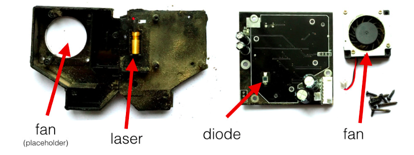
Laser scattering
The ultimate goal for this week is to create data with the sensor SDS011. Here are my steps:
- How to communicate and power the sensor
- Coding and read data
- Create a board
- Push code into this board
How to
1-What are the need for the SDS011
- I have to download the datasheet of the sensor SDS011. It gives me two choices; working in UART with the tx, rx or working with PWM. The choice of working with tx and rx is very easy because the accuraty of the data generating by the PWM is very delicate and sensitive. The big issue is to have the zero reference and to make it right you need a controle space where you know the exact amount of particules in it. This calibration needs an industrial particules reader that can be trust to make the reference reading. Common people don't have this costy equipment and with tx rx, the reference is already done in industry so in that case it's better to trust the industry. Later one (in 6 month or 1 year, it will be great perhaps to compare the data generated with the newest BAM or equivalent to evaluate the accuraty of the data). Fun fact, I met Béatrice Arruabarrena, a researcher on the data and she explained me how the exact precise data is not really important when come analysing big amount of data. Because every sensor is different, the important is not really the number, but to observe the same increase and diminution. So if your data generated is really off by 100pm, and we can observe a augmentation on this sensor and other one. Then we know that at this moment we have a real augmentation and your data generated can count. To conclude that point, even if you don't have a BAM, and you create an open source project and generate data. It's worth it and contributes to a greater common good if you data can be match with other similar data of course. (We still need to sens the same element and here is the pm10 and pm 2.5).
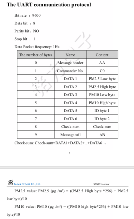
- The Universal Asynchronous Receiver Transmitter or UART is a communication protocol that I will use to create the data. I didn't understand the first time I read the datasheet, but now it's clearer. To be able to create the data, the sensor sends 9600 bits per second. A standard RS232 format (or we can say serial communication) sends series of 10bits. (A serie of 10 bits is called 1 byte). Each bits have a different information and can be read individualy or by group. If you see the picture illustrating the UART communication protocol from the datasheet of the SDS011 sensor, you can see that we are sending 10 bits to create the data PM2.5 et PM10
- 0 to 1 - bits to start the sequence
- 2 to 7 - bits to create the data
- 8 - bit that assemble the information of the previous 6 bits
- 9 - bits to close the sequence
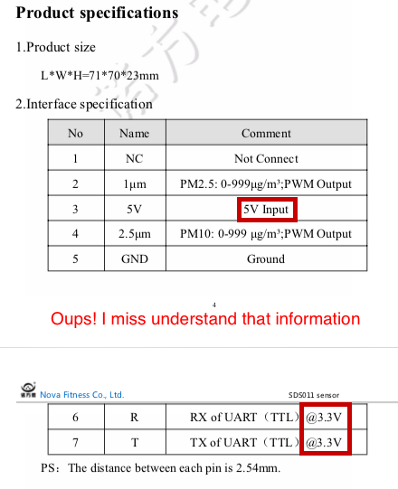
- To read well all the informations, we need to communicate with the same baud rate (9600) and with the good voltage. I can communicated with this sensor in 5V, and the tx,rx need only 3V. The way they have written in the datasheet I was thinking that the alimentation of the sensor need to be 3V. You will see in the next section that I make it work at the beginning with the 3.3v on a arduino, but the number generated was really (big time) off and I didn't understand why. After fiew interesting conversation we prob the sensor and confirm that 5V is needed for alimentation and the tx, rx, take around only what it needs int that 5V so it take 3 to 4v.
Here is the sensor SDS011

UART communication protocol from the SDS011 datasheet.
When it said input 5V it's because it's 5V. No mather the other number.
2-Coding and reading the data
- I want to start by creating the code for the sensor because it will influence on my mcu that I will choose. Some people strongly advise me to do so, so I can choose a mcu with enough memory spaces. The Aruino IDE is great, but the library is taking a lot of spaces. We just need to be aware of it.
- Just to test the sensor, I put it on a commercial Arduino Uno and try different code to be able to read the data.
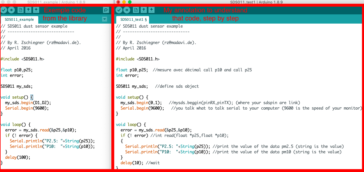
- I start that day by writting on google " Code for sds011" and I discover that somebody have made a Arduino library specificaly for it. I download it, slide the folder in the Arduino folder library and try the exemple code. Result: It doesn't work. In the picture, you can see that I annotated the sequence of the code to help me understand what is wrong. But anyway that sensor is well used by many project so I am sure to find other thing that work on internet.
- On Google again, I search some tutorials that where using this kind of sensor but almost all of them where in german. I try to figure out what it means but I don't have enough time to learn that much german in one week.
- With the help of my instructor, we found another library for SDS sensor and that one is fully documented and allow you to do many different action like putting the sensor in a sleep mode, making working periode so the life of the sensor could be longer, etc. Big thank to lewapek of MIT for that friendly sds Nova Fitness library for dust sensors.
- I first try with the quickstart exemple and after I experiment some variations. At my big surprise, it works very well.
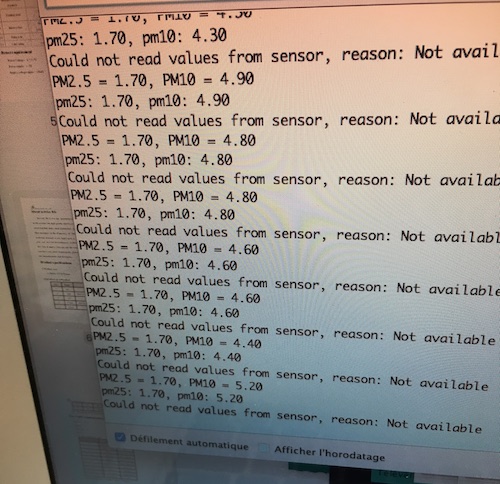
- What is great about that code is that it will tell you if it cannot read the value. Making your code talk to you is defenitly easier during the trumble shooting. (like when you invert your rx, tx pin, been there, done that)
- When I was able to generate my first data, I take the same code in a 5 minutes period and test 2 other sensors sds011 to confirm these data. I discover that each of them have their own level but still proportion. The reation seems good, but the number not. The AQI (air quality index) reference that a pm2.5 of 119,10 is a unhealty air for everybody so that data is too higher and I really don't think that the inside air of échoFab is so unhealthy. I search for a air particule monitor commercial or industrial to confirm the base level, but I didn't find some (and later on I discovered that it was the effect of powering your sensor on a 3.3V not a 5V. When I powered with 5V the number was very much more normal).
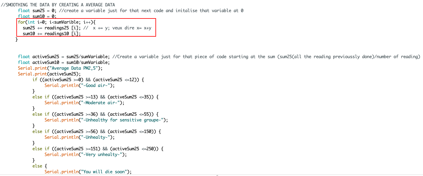
- When you work with sensors, you also have a problem of noise. It means the data is changing value but each unique value is not necessary perfect. In my case, if I want to know the level of particules and observe an increasing or decreasing level of it, I should smooth the result working not with the raw data but with a average data. To do so I will need to track at leat 5 data in the past, make a average number of pm2,5 and pm10.
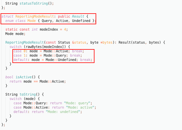
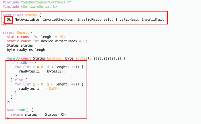
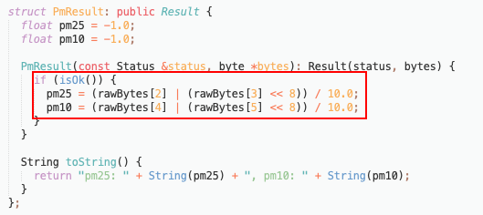
- I open the library code to understand the exemple code and to see the relation ship between each element. Like I said before, I am new in the field of coding and electronic, but I am getting good to understand the syntaxe of it and I was able to understand a lot of things that explain the structure of the present code. For exemple, I found the actual formula that creates the data, the speed baud in the code, the different status of the sensor. What means it's OK in the code. It's the fonction that confirm that everything is good or not. Here are some basic fonctions that I was glad to learn:
- Int or float: When you write a code, it's all about memory so calling a int is telling the software that the number have no decimal so don't bother to give extra space for decimal for this one. Float on the other hand is number with decimals, so it will reserve extra space for the decimal.
- Serial.print or Serial.println: Depending if you are communication in analog or serial, you will write Serial.print to print something (a value or a sentence) in the serial monitor. The thing that will be print will be position on the right the previous information. If you want to print something under, than yu write Serial.println,
- For: For is to create a small loop in the big loop. Usually you arduino code is divided by a set up and a loop. The code will read up to down and go back on the top of the loop to read it constainly. So the section before the loop is only read once. Also, technically a good code will not write a repete action. For exemple, in my code I wanted to read 5 data before doing anything first. I inserted a forloop to create smaller repeated action.
- If: I found the if very powerful because you can think in if and base all you action on this. When you write if (you put in parentesis the condion of the if). For exemple, if (x>4) than do that, else do that.You can also have 2 conditon if (x>4) && (x<2) the && meens that you have to respect both of condition. You can also go with if, else if , else for multiple discions choices.
The SDS011 library and my code anoted

The Nova fitness SDS dust sensors library making the sensor work differently

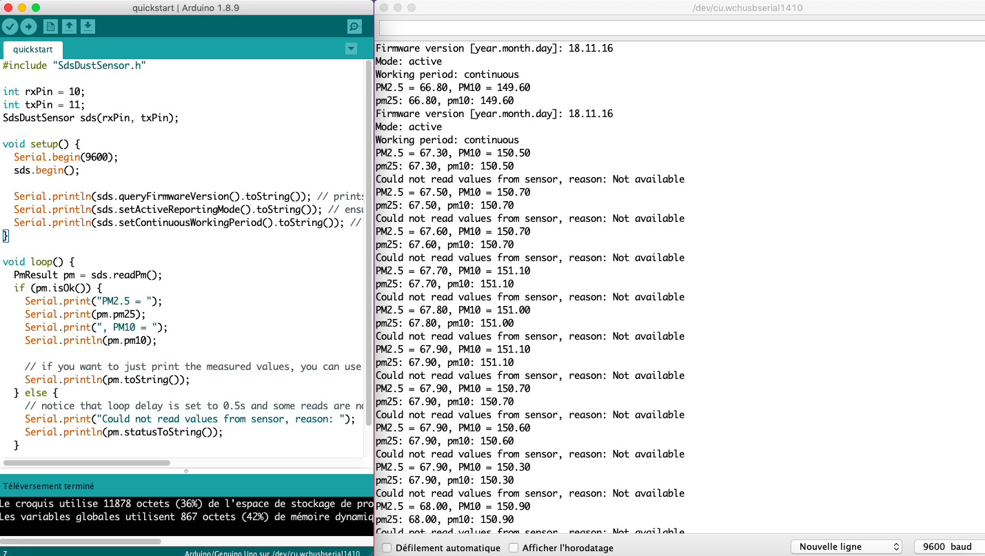
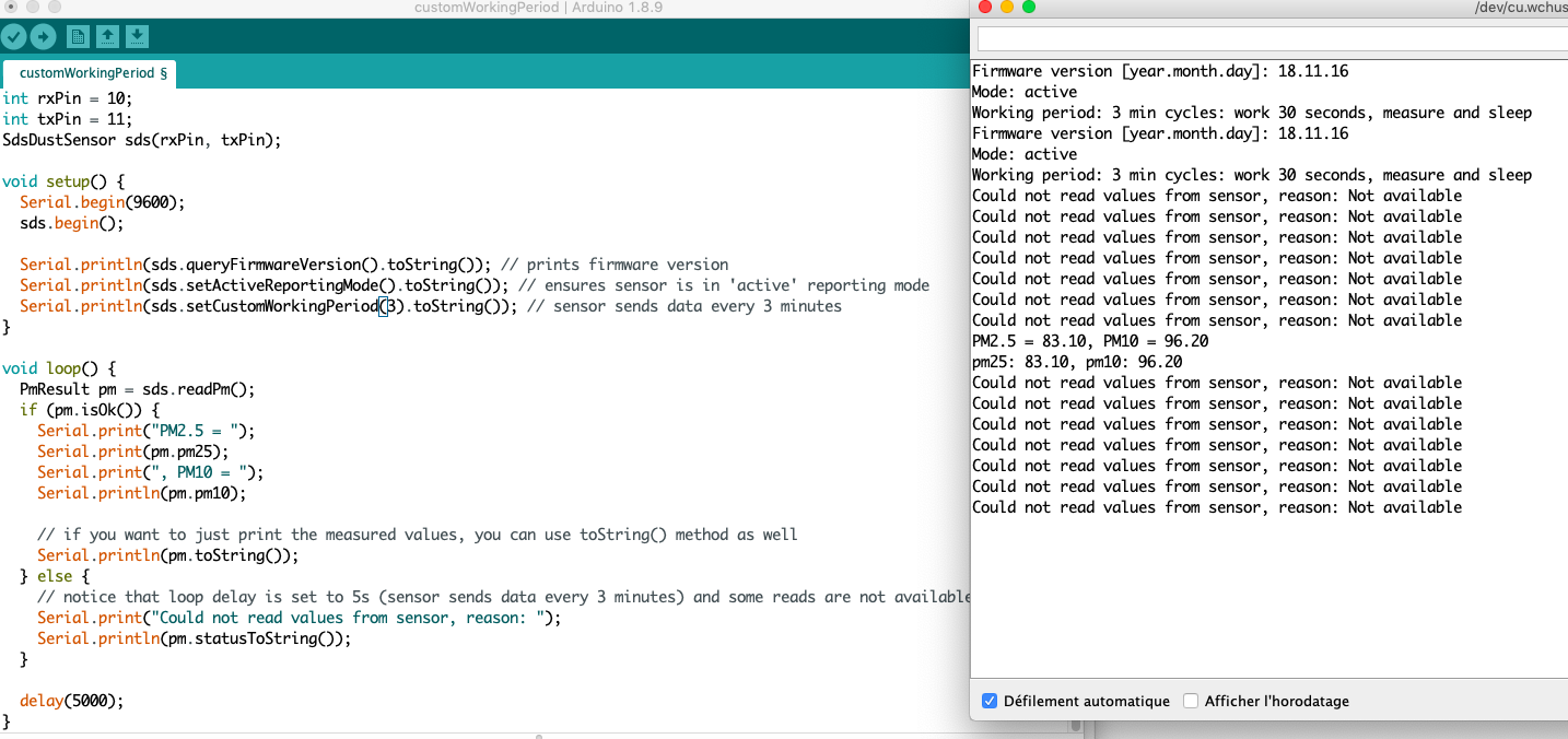
Comparison of the data from 3 different sensors
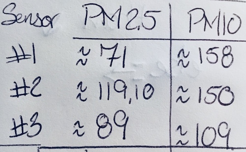
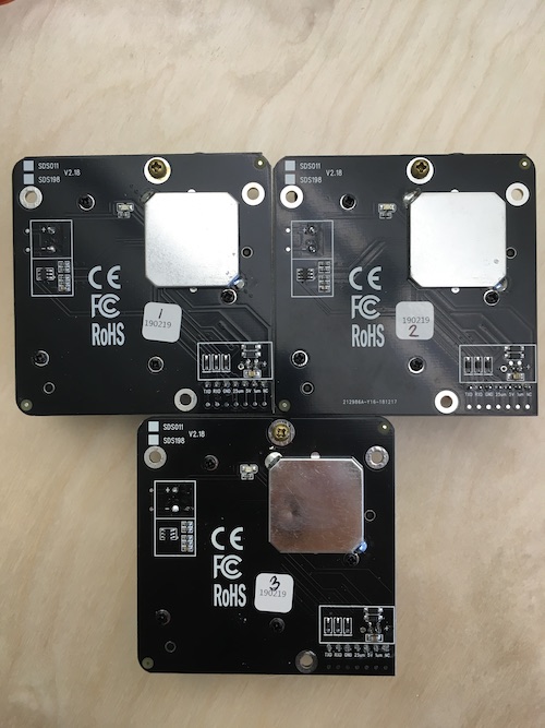
Good data value with 5V input
A for loop to create the summary of PM2,5 et PM10
I open the library code to understand better what option I haved
3-Making the board
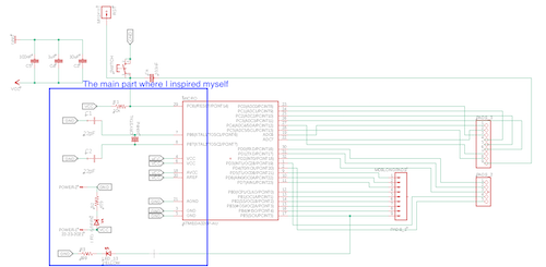
- At the biggining, I try to take the Arduino Uno schematic to inspired myself to create the board, but lucky us Satchakit is exactly that. It the MCU atmega328p and the strick minimum to play with it. Thank to Daniele Ingrassia for that work.
- So I inspired myself from that previous kit. I change the atmega328p for the atmega328pb with what was our version here at the lab. Both of them are very similar exept for the pin out. I download the datasheet and start to design my board.
- I wanted to have :
- 2 pins for the alimentation of 5 V.
- a led who will turn on when the board is power
- 1 FTDI
- 1 ISP
- 1 connector for my PM sensor. It connect very well with the same type of connector has a FTDI
- I need to convert my power from 5v to 3v so I can aliment well the PM sensor. (spoiler alert, I will change that later one)
- 2, 3pins connector for my servo motor. (The same type of connector has a FTDI fit very well also)
- I would probaly play with that circut so I connect some extra pin of the atmega328pb to let me play alittle bit more.
- 1 crystal or resonator to make the board go on the same paste
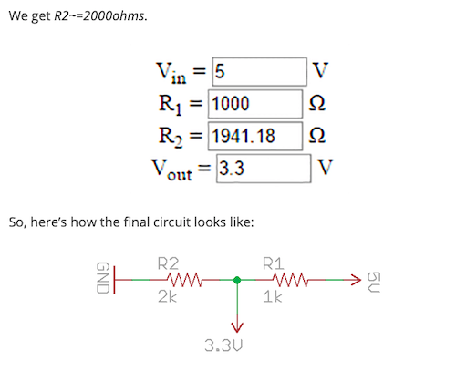
- This site shows us how to shift 5 to 3.3v with simple resistance. I will try that.
- On eagle, I add all my part in a new file.
- For the atmega328pb I when on SnapEDA and download it.
- For the header I could use a FTDI but the inscription was wrong for what I would like. To do that I create my own library and footprint.
- To do so, when you open Eagle, select Files, new, library. Then, click on add symbol and draw your symbole that will appear in your schematic. Don't forget to add pins to you draw
- Add footprint: You have the choice of drawing it or importe it. I import the FTDI footprint.
- Click on New device and choose the symbol you just made.
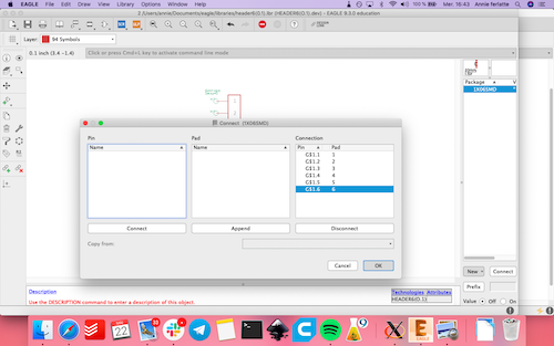
- Confirm each association pin and press ok. You have made your first homemade footprint!
- Find the rest of your element to connect and do the schematic
- I try to put my 2 servo motor pin on a pwm pin. It would work even if not, but after a long conversation with my colleague Françis, I found that it's naturaly easier for the atmega328pb to control the servo motor because basicaly a servo motor understand pulse. That pulse will tell the servo motor to turn at a certain degree.
...a moment later, creating a second board before milling anything
- Bomi was trying to do the conversion of 5v to 3v with resistance and it doesn't work at all so I decide to take a converter 5v to 3V.
- She tries also to bootload the atmega328pb and it is really not a succes with the software. So I made a decision of baby step...my first bootloading will be with a well documented method (traditional) and after the fabacademy when I understand more and more than I will focus on how to bootload this non-official board. So I change my chip for the atmega328p (that we order right away)
- I also want to work in spiral and test the circut first with simple led, so I add 3 different led on my circut.
- The nesting was terrible and if that circut doesn't work, all these part will be lost..and it's after all my first time creating a complex circut with a atmega328p...(I'm really impressed of my learning on electronic on how designing a circut and make it work.
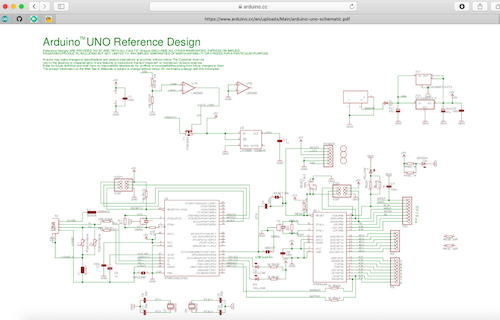
Here are the Schematic of Arduino Uno that I use to understand and take has a reference
Here are the Satchakit schematic with the main part I inspired myself.
This is from the site I explain to convert the 5v into 3.3v, just putting the right value of resistance, (but we discover that in reality it did not work well )
To replace the atmega328p with a atmega 328pb I needed to have the eagle footprint. I whent on SnapEDA and download it. Very userfriendly.Click Download and choose a format. Integrate it in your folder libraries and that's it!
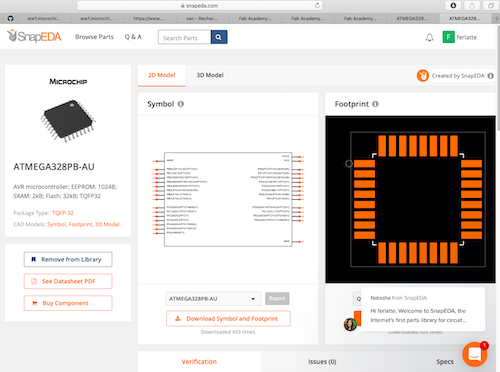
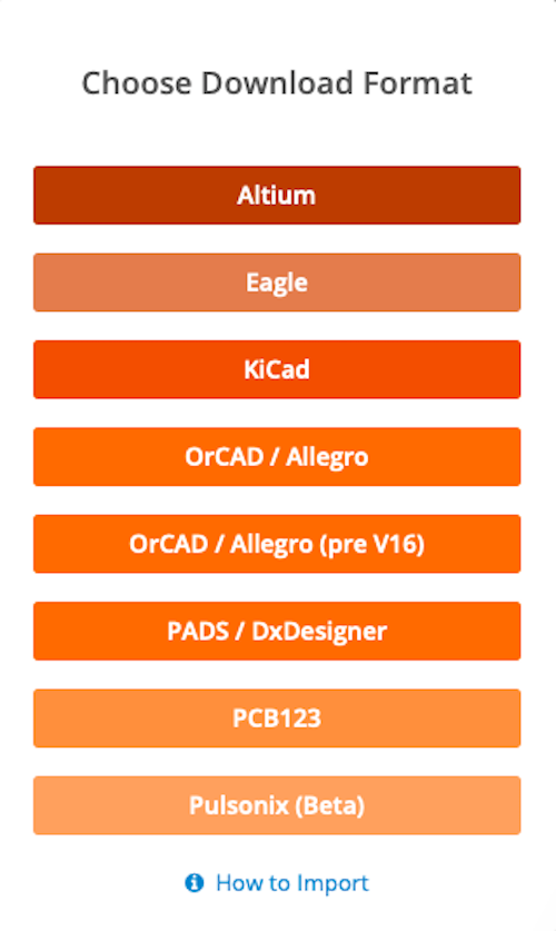
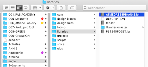
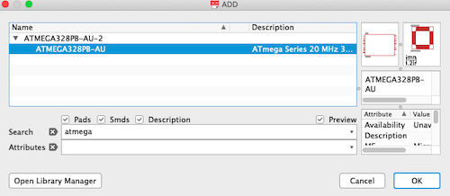
To create a footprint in Eagle. Create a new library and inside, create a symbol, a footprint and a device
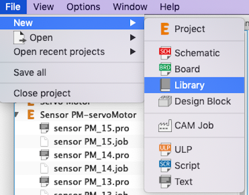
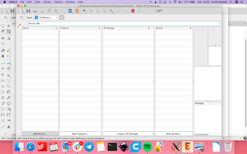
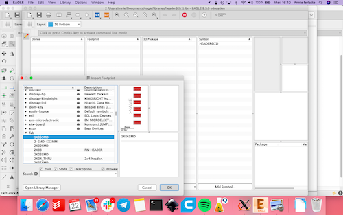
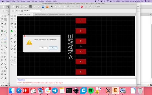
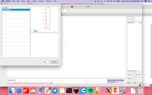
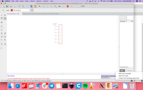

Match the symbol pin with your footprint pin and it's done!
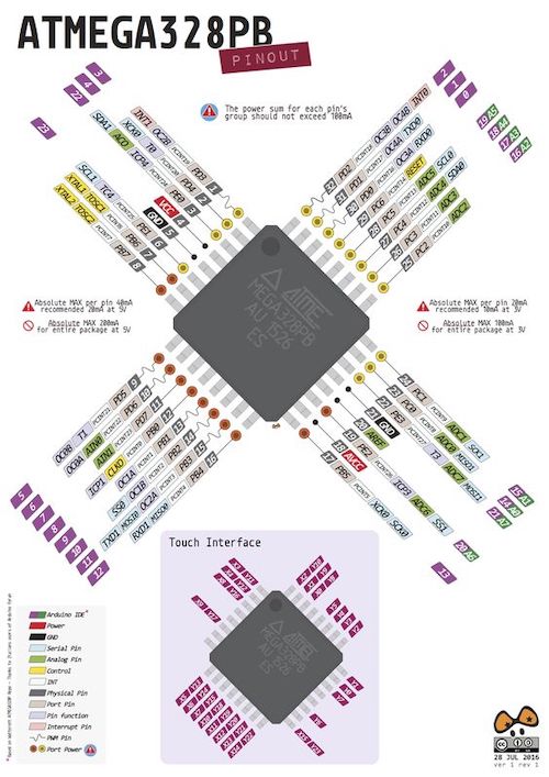
Don't forget the pinout to know on witch pin you will connect your things.
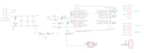
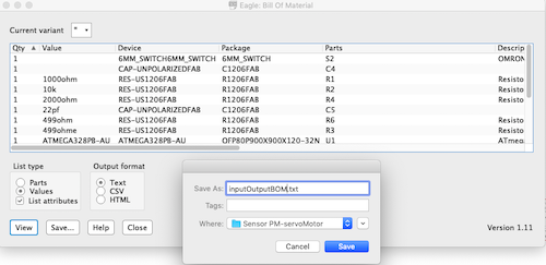
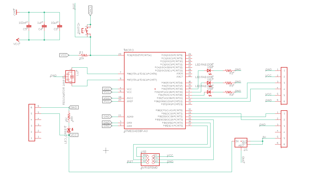
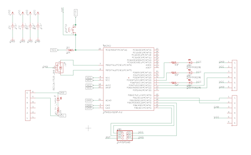
After a little while I am able to complete my schematic and generate my BOM from eagle.
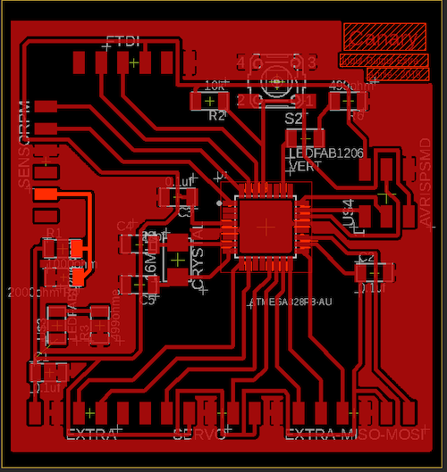
Here is my complete board on eagle. All the base plan is a GND. This strategy is easier for me to link every GND possible
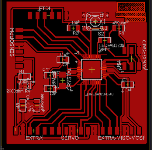
Here is my 5v vcc
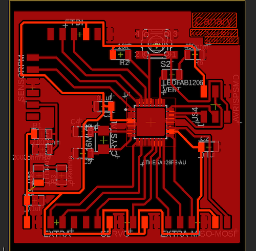
Here is my 3.3v vcc
4-Milling and bootload and make it works
- The process of milling the board is documented in many weeks like the electronic production week. I will talk more about the new things that I discovered in this process.
- My eagle schematic and nesting is done so I picked my pieces soldered...and discover that my converter was under the pins..I didn't think about it when I nest everything...oups but I try to bootload anyway.
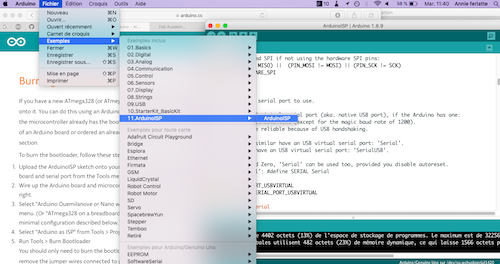
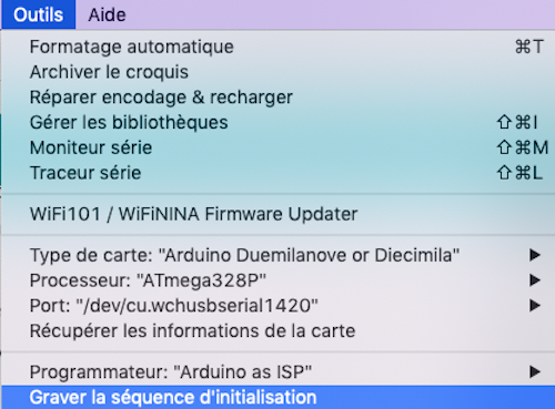
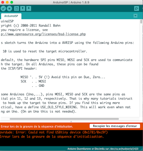
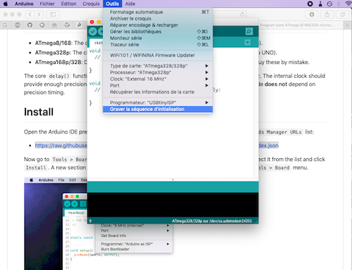
- I transform a Arduino in a programmer (pushing the exemple sketch 11. ArduinoISP in the arduino and wire it to my board. I was very happy that the led light so was guided by this tutorial From Arduino to a Microcontroller I then choose the card Duemilanove, the ATmega328p and bootload....The result was please try again. So I try with an AtmelICE and the equivalent of a fabisp but commercial...Good try, but no.
- This is where I finally discover my mistake of the power 5v by probing the sensor with the code.
- The sensor has sometime some problems to read every data, it is because the paste of reading is too fast. The data printing match with the bits sequence that we saw. I was really glad to see physicly what was going on in that sensor. I start to understand all this bits and bytes really mean. Even if I knew that it was a electric pulse, I didn't realize all the sens of it.
- I make few other changes. I change the way my led was alimented. Instead of alimented my LED by my MCU and go to the GND, I put them directly on vcc going to the MCU. It's another way to do thing. The MCU can take led alimentation for sure it's not demanding, but I try another ways.
- I also add the final shape I wanted and holes that can be screw on the sensor. I try to put text, but it is way too long to the CNC.
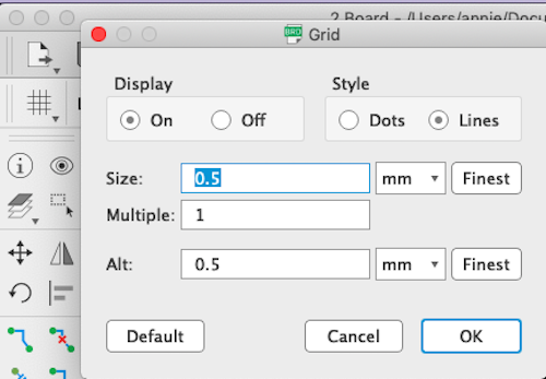
- To mesure the position of the holes, you need to activate the grid of you eagle board and than you will have the dimension.
- I mill it, soldered it and power it. And the light is!!!!!
- I try to bootload it differently. I download the library From Carlosfr. It's a library to bootload Atmega328p.
- That was the exact same process of the ATiny44. I wire the programmer with the board, and bootload...the result was YESSS IT WORK!. But then the leds where starting to be really bright and some smoke was comming out of the connector of one led and some other connector.
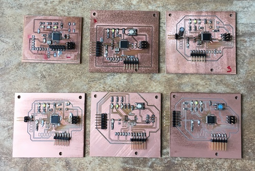
- I made few versions and try different things. I finally replace the only capasitor for a 10uf and that seam to stabilize the led. Also, we were using a new flux (the red thing that you see on the board. This product, when low heat is apply, starts to melt and in the small area like under the connector or under the resistance for example, it carbonises, smokes and bubble up and seam to disturbe the VCC line.) The thing I never understand is that in many of my board, longer the board was alimented the connectivity between the vcc and the ground seems to grow so I start to unsoldered the parts and at the end I only have my alimentation, a led and a resistance and the other connector. The LED was taking between 10 and 50mA and fliker for no reason.)
- Knowing that I take the chance to mill again a board and I solder it in a freak mind. No Flux, I check my connection and they where all under 0,7 of resistance. I do it by section, I solder the LED and FTDI alimentation and I check the current...It is good, I soldered the Atmega328p with his accessorie (using the intern clock) I try to push a code but not the bootloading, only the blink a led. It work again!!. I soldered the rest, I check the connection, then I check the current consumption, it was stable. I push another blink a led code using the 3 led linked to the board. It work again!!!! I beggin to be real exiting! I solded the connector for my sensor and push a simpe code that blink my red led if a value was found and blink the white led if the value was missing. AND IT WORK AGAIN!!! I was talking to a person who develops circut in his every day life and he told me that at the speed I am going, this circut didn't use the benefit of a resonator. So finally, this week is working.
My final schematic
Soldering the board and keeping track of my component
First try and the smoke comes out from the chip. Here is the short..sneaky hidden short.
After reparing the short, I try to bootload with the arduino
Analysing the sensor and this is my data sequence
My second board with few changes. Putting some holes to hold it.
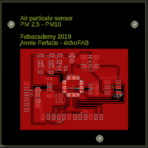
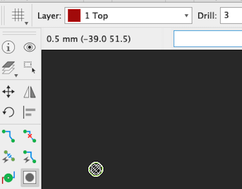
To put some holes, activates your grid by clicking on this grid symbole
That bootload work!
Different version that I try
The final board that work Finaly
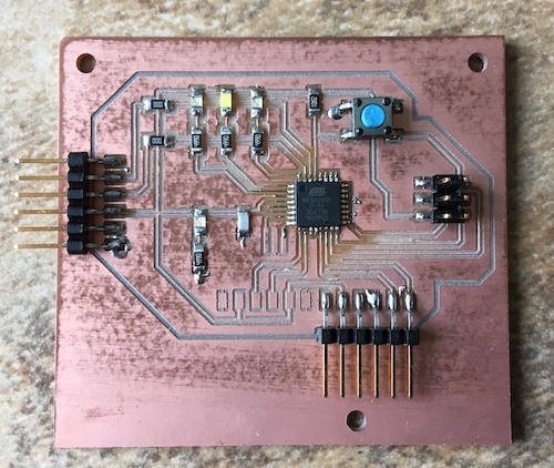
The LED red on the sensor flash at the riddem it take a reading. The LED red on my board is capting data, the LED white on my board say that it's not reading data. It is normal the MCU is demanding to quickly.
The moral of this story
I adopt some new habits to take to create circut. I undust my circut before doing anything and I really learned to use frequently the multimeter. Before and after every step to confirm the connectivity or the current or voltage who pass thrue. I am more conscious about the current consumption of the component and how to observe, analyse and make good hypothesis to debug a circut. At the beggining, I was thinking that electronic was more mathematic than that. You put a wire between this section and this section and Voilà everything works only maybe the coding part. But at my suprise there is many factors to take in consideration. Every consumption of the component, the heat apply, the way vcc goes and the ground who needs to comeback (always design the vcc and ground like a water canal. Main pipe who go until the end of circut and smaller pipe from their to diminish the noise). Try to isolate the LED from the resonator to don't interfear with that fibration..etc. That was a precious experiences and a big success for me. Files
Contact
Annie Ferlatte
ferlatte.annie@gmail.com
Montreal, QC, Canada