Concept and Research
For my final project, I wanted to create a CPR training dummy. I will use a pressure sensor to collect data on compression rate and depth. To create a realistic model, I will mold the CPR dummy body.
Project Management
From the beginning of this class, I planned to incorporate a majority of my final project intp my weekly assignments.
For the first few weeks, I planned out each addition to my project during the same week.
Here is my original “schedule”. I would update it after I completed the assignment for the week, so it served little purpose, other than archiving my accomplishments throughout the course.
Week 1: Principles and Practices - Final Project Idea
Week 2: Project Management - Website
Week 3: Computer Aided Design - Lung Pump, Vest Renderings
Week 4: Computer Controlled Cutting - Living Hinge Vest
Week 5: Electronics Production - Programmers
Week 6: 3D Printing and Scanning - Check Valve
Week 7: Electronics Design
Week 8: Make Something Big - Coffee Table
Week 9: Embedded Programming
Week 10: Molding and Casting - Skin Overlay
Week 11: Input - Force Resistor
Week 12: Outputs - LED
After week 12, I began planning out the additions in advance so that my project would be completed in time. I made this change after reflecting on some of the components that I had amassed throughout the first few weeks. Many of these parts (lung pump, living hinge vest, check valve, etc.) were completely irrelevant in terms of my final project and ended up being discarded. With the final project deadline quickly approaching, I changed my approach and developed a more structured checklist that I scheduled with my weekly assignments.
This was my new and improved checklist/schedule.
Week 13: Applications and Implications - Gantt chart
Week 14: Networking and Communications - A, B nodes
Week 15: Mechanical Designs - POV Machine
Week 16: Interface and Application Programming - Graph
Week 17: Machine Week - POV Machine
Week 18: Wildcard Week - Embroidery
Week 19: Invention, Intellectual Property and Income
Week 20: Project Development - Finishing touches (Edit: circuitry container)
To give myself a snazzy visual to track my progress, I created this gantt chart. Near the end of my final project development, I ended up straying a little from my intended schedule due to several events including Father’s day!
Here is the gantt chart I developed.
The following links to work from previous weeks that I included in my final project.
Created mold for CPR dummy body
Fabricated and coded force sensor board
Outlined and organized project documentation
Developed processing program
Established copyright license
Printed circuitry container and cast CPR dummy body
Research
My project was inspired by a presentation by Jenni Buckley who explained how to make the physical components of the vest using springs and metal plates. (I attended Dr. Buckley’s Perry Initiative Outreach Program which works to expose girls to medicine and engineering.) I hope to focus more on digitizing the compression data.
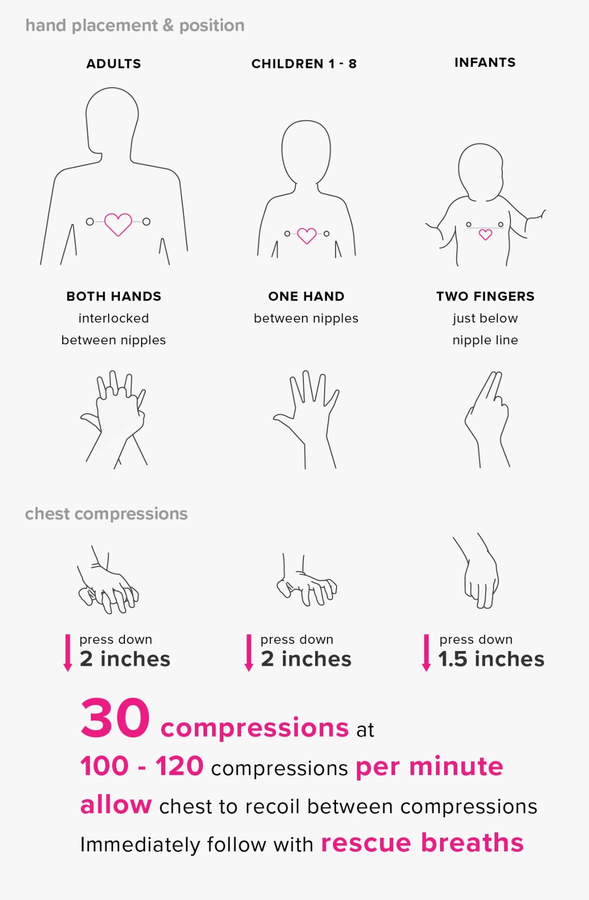
After listening to Jenni’s talk, I researched the amount of force applied during CPR. According to the CPR Certified Blog, around 60 lbs of force is applied if the compressions are 2 inches deep. This infographic shows the relative compression depths, areas, hand arrangements, and timings for the different age ranges.
Napkin Sketch
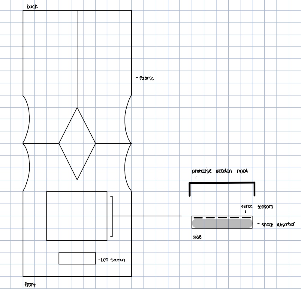
This was my original sketch for my final project.
Previous Versions
As of 2019, there are many types of CPR dummies for sale. Here are a few versions from the most notable brands with their price points as of 2019. The dummies marked with an ‘*’ are digitized.
-
Laerdal ~ $2,953.00
-
Nasco* ~ $175.00
-
Prestan* ~ $143.14
-
Simulaids* ~ $160.60
-
Feedback Products* ~ $175.00
-
Gaumard ~ $995.00
While these manikins matched my desired product, I did not want to spend $100+ dollars on the commercially available dummies.
Similar Tutorials
Here are a few DIY tutorials that I found online.
I did not find a tutorial that truly matched my desired goals, but I thought the last two articles provided some relevant information!
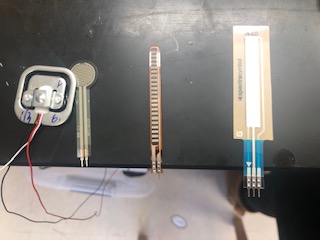
Components
After looking into these cool projects, I researched the foundational technologies that I thought I would need for my project.
-
Force Sensitive Resistor ($11.25)
-
Load Sensor ($10.95)
Force Sensor
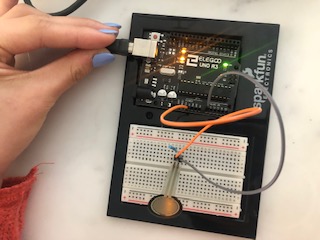
I decided to work with a force sensitive resistor for my final project. At first, I debated between using a force sensor or a flex sensor. I found sample projects for both sensors, but I decided to use the force sensor because I thought it would help to simulate the correct compression area on my dummy.
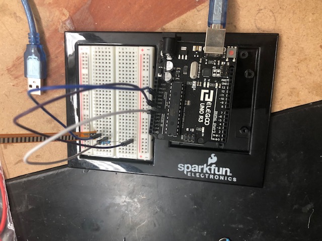
Adafruit Tutorial for this week)
I used GND, 5V, and analog pin 0 on an Arduino for this test.
Here is the code I ran for my test.
/* FSR simple testing sketch.
Connect one end of FSR to power, the other end to Analog 0.
Then connect one end of a 10K resistor from Analog 0 to ground
For more information see www.ladyada.net/learn/sensors/fsr.html */
int fsrPin = 0; // the FSR and 10K pulldown are connected to a0
int fsrReading; // the analog reading from the FSR resistor divider
void setup(void) {
// We'll send debugging information via the Serial monitor
Serial.begin(9600);
}
void loop(void) {
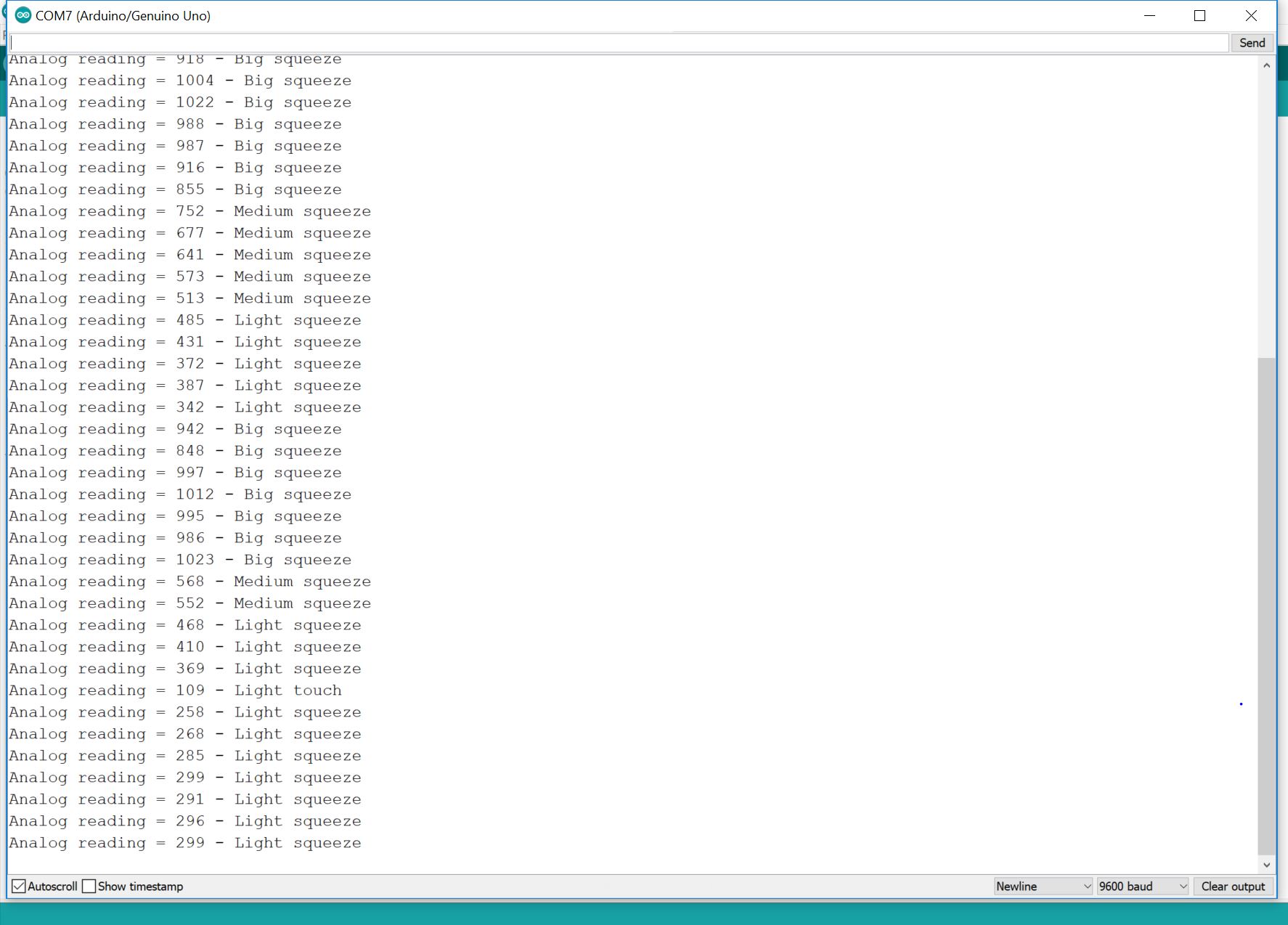
fsrReading = analogRead(fsrPin);
Serial.print("Analog reading = ");
Serial.print(fsrReading); // the raw analog reading
// We'll have a few threshholds, qualitatively determined
if (fsrReading < 10) {
Serial.println(" - No pressure");
} else if (fsrReading < 200) {
Serial.println(" - Light touch");
} else if (fsrReading < 500) {
Serial.println(" - Light squeeze");
} else if (fsrReading < 800) {
Serial.println(" - Medium squeeze");
} else {
Serial.println(" - Big squeeze");
}
delay(1000);
}
Here’s a video of my test.
Here is a photo of the serial monitor readings.
Using this different tutorial, I powered an LED with the force sensitive resistor.
To learn more about the inner workings of my force sensor, I looked at this website.
DIY Force Sensor
I also read this article on DIY force sensors and was inspired to create a DIY version of the sensor.
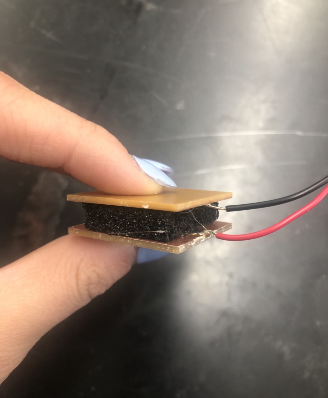
I milled two squares out of the one sided copper PCB. Then, I soldered two wires onto the plates and glued it together with a piece of conductive foam.
This is my finished DIY force sensor.
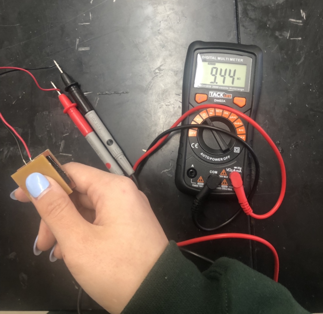
This is the resistance with a small amount of force.
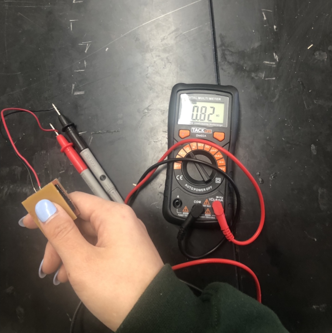
This is the resistance with a larger amount of force.
Adapted Force Sensitive Resistor
In preparation for my final project, I also adapted a force sensitive resistor to work with the pin headers on my satshakit board with the help of Dr. Harris.
To adapt my force sensitive resistor, I soldered the two prongs of the resistor to two female wires. (I stripped the other end of the wires so that I could solder them.) After the wires were soldered on, I used heat shrink to isolate the connections. I also used heat shrink around the prong to wire connection to make the adaption more durable.
Here is one of my adapted resistors.
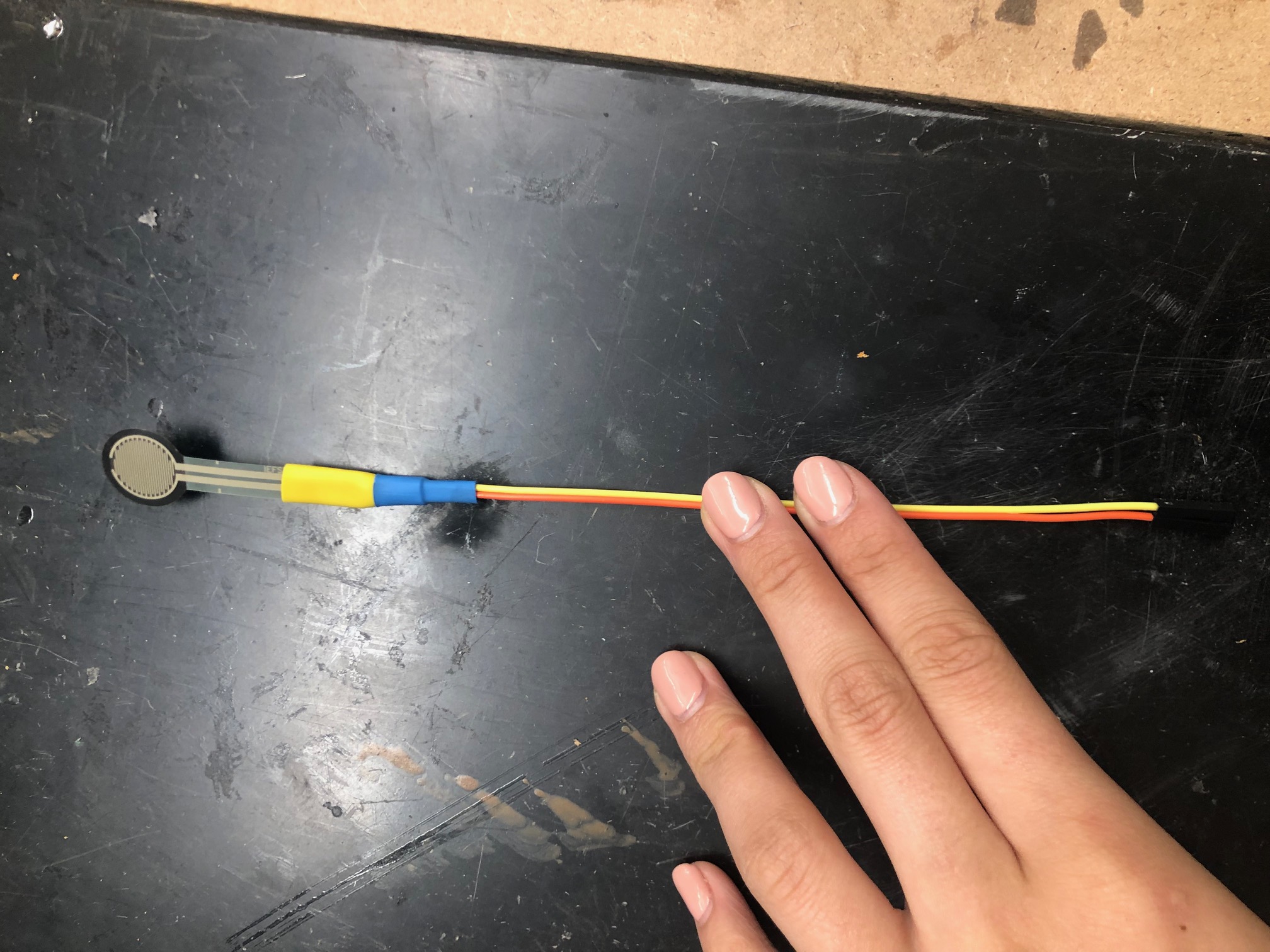
(Warning: After looking through the item description on the force sensitive resistor website, I learned that you are not supposed to solder materials onto the prongs. Instead, they recommended using female headers.)
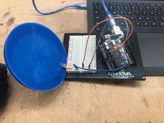
Silicon Comparison
I decided to compare the readings of a flex sensor and casted flex sensor to see how the data would be affected. (While this was not perfectly aligned with my final project as I decided to use a force sensitive resistor, this test provided me with good insight that I was able to apply to my final device).
I found the tutorial for this setup from this site.
Once I had readings from the plain flex sensor, I tried to mold the flex sensor in silicon to see how the material would affect the values. From this initial test, I found that the silicon dampened the readings of the sensor to an extent that the values were almost unusable. (The readings were basically bent or not bent.)
Without Silicon:
With Silicon:
I believe that the dampening effect of the silicon could have been lessened if I poured less material around the sensor. In the future, I found that I would need to place the sensors near the bottom of the mold.
Bill of Materials
After reviewing all my research, I developed the following bill of materials for my final project. I changed it as I advanced my project.
This is the updated material list for my final project!