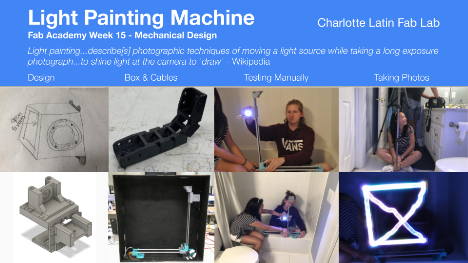
15. Mechanical Design
This week’s assignment:
group assignment:
design a machine that includes mechanism+actuation+automation
build the mechanical parts and operate it manually
document the group project and your individual contribution
Planning
Brainstorming machine ideas
We met to discuss possible machines to design and build. Our ideas include:
-
Drawing machine
-
Mandala machine
-
Wire coiling machine
-
Camera slide
-
Vending machine
-
Light drawing machine
~~We ultimately settled on a vending machine.~~
Due to time constraints, we eventually decided to change our plan to a light painting machine, using much of the same base components
Examples of Arduino-based Vending Machines
Scheduling
We decided to schedule out the week ahead of time.
Wednesday - Friday: Part Design/Fabrication
Saturday: Finish part fabrication
Sunday: Assembly
Monday - Tuesday: Finish assembly, testing, begin automation
Break for Interface/application programming
Finish automation
Parts needed
-
Plywood
-
Aluminum tubes
-
Belts
-
~~12 gauge wire~~
-
~~Washers~~
-
~~Nuts~~
-
~~Threaded rods~~
-
~~Buttons~~
-
Satshakit board (Original kit / Kai’s altered board / Kai’s board files)
-
Stepper motors
-
Neopixel
-
Cable management
-
Screws
Sketches
The above 3D design is not to scale; it is just intended to show what our X axis mechanism will probably look like.
Machine Axes - Will
I started this week out by working on the design of the two axes that would make up the core functions of our machine. First, I found two two-phase hybrid stepper motors laying around the lab that were the same exact model number 17HS4401. I also found four 3/8ths inch aluminum dowels that we could use as the tracks of our two axes, and after that I went ahead and began designing some 3D printed parts to put it all together.
3D Design
We were going to need something to help hold all of these parts together, and because of how specific all of the measurements and design requirements were I figured there was no better tool for the job than our 3D printers. I opened up fusion 360 and got to work on some designs by using calipers to get exact measurements on everything. I use a tolerance of .5 mm for everything that would end up coming together, which I have used in the past because it always seems to work well with these printers.
This piece was what we originally used to hold the motor in place with the two dowels on either side, and it only took a couple of hours to print it out. Thankfully, It worked well and held the motor and dowels in place perfectly.
Next, I knew I would need something for the other ends of the dowels, and I also knew that since we were going to be using belts for the movement I would need to have a space for an idler on that side. I made some slight changes to the first endpiece model and then I printed that one out as well.
Finishing up these pieces meant that I now had the basis for the x axis completed, but I knew that there was still more to come. We still needed some way of getting a z axis on there as well, and that meant that I had to design some sort of gantry system for the rodas that could also support another axis itself.
When I first started trying to design this piece, though, I quickly realized that the printer probably wouldn’t be able to competently print out a working part like this because of how the dowel holes would create too many overhangs regardless of how you placed it on the print bed.
This got me thinking again. I needed some way of attaching the second axis to the gantry, but I couldn’t print out one solid piece to do the job. I tried out one of my first ideas as more of a test than anything else, but thankfully it actually worked quite well. I figured than rather than designing one entirely new piece, I could work with what I already had and just make some modifications to the already existing pieces. I extruded some material on the sides of the motor housing that I used before to make room for four screw holes, then I extruded the same sized holes into the gantry.
With parts like this, I could efficiently print out both pieces without too much risk of the print failing due to excessive overhangs or other things that come along with very complex 3D prints. I got both parts printing that night, and when I came back the next morning they were ready to test out.
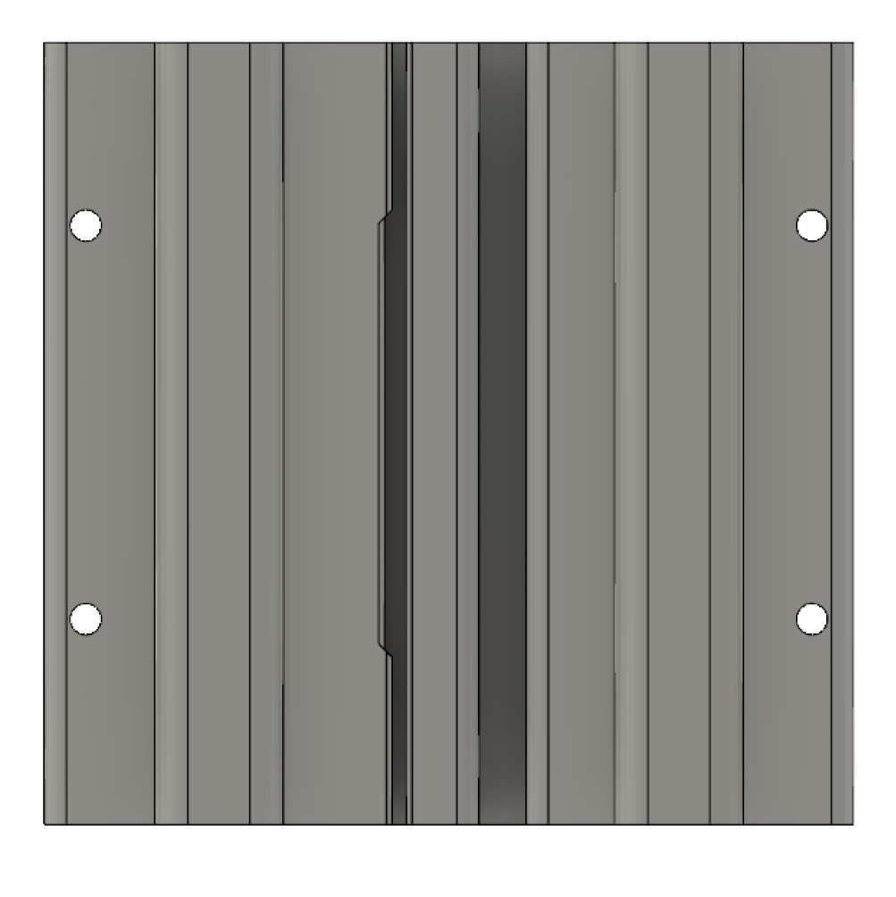
Luckily I realized that this gantry piece wouldn’t actually work before I screwed it all in. I still needed some way of securing the belt to the gantry so that the x axis would move when the belt was turned. I added in this shape along the bottom to keep the belt held in place with itself. This way, the teeth of one side of the belt would lock themselves into place with another part of the belt, effectively holding the gantry in place for any sort of movement.
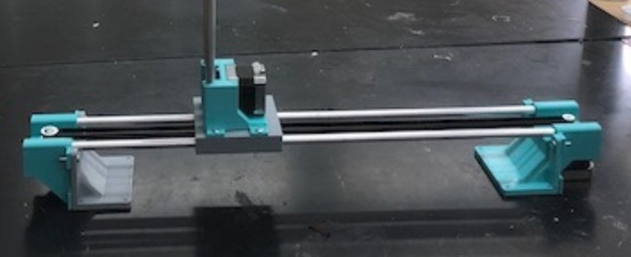
I printed this new gantry piece out, and once it was done I could finally screw it into the z axis base. I got this attached, then I got all of the pieces that we had so far put together. The machine looked pretty good, but I was concerned about how secure the two end pieces would be just free floating there. At that point I realized I could just use the same piece that I made before with the screw holes and just put that at the ends of the axis because all of the other measurements were exactly the same. I printed out two more of them and once they were done I attached them to the ends as well.
Now I just needed to print out a part that could secure the two ends of the x axis to the same base, so I made two L shaped parts that would fit onto either end and provide screw holes to attach the machine to one solid base.
Then, lastly, I printed out another one of these gantry pieces for the z axis and slid that onto the two rails. With that, I had finished up all of my 3D printed parts.
The Belts
For the belts, we used these parts from Amazon for the actual timing belt itself as well as the gears that would attach to the motors, and we used these as our idlers on the opposite ends of the belt. Once the parts all came in, I was able to attach the belts, and thankfully my measurements worked out perfectly so that the belts all slid right into place.
.pic of everything in place
With that, I had completely finished the work for the two main axes of the machine.
Cable Track - Kai
To keep cables tidy and protected in the machine, I wanted to emulate the caterpillar-looking tracks used for cables on our laser cutters and ShopBots. With the help of Mr. Rudolph, I discovered that these tracks were called drop chains. I quickly found and downloaded a design I liked on Thingiverse (Cable Chain by ModelStation).
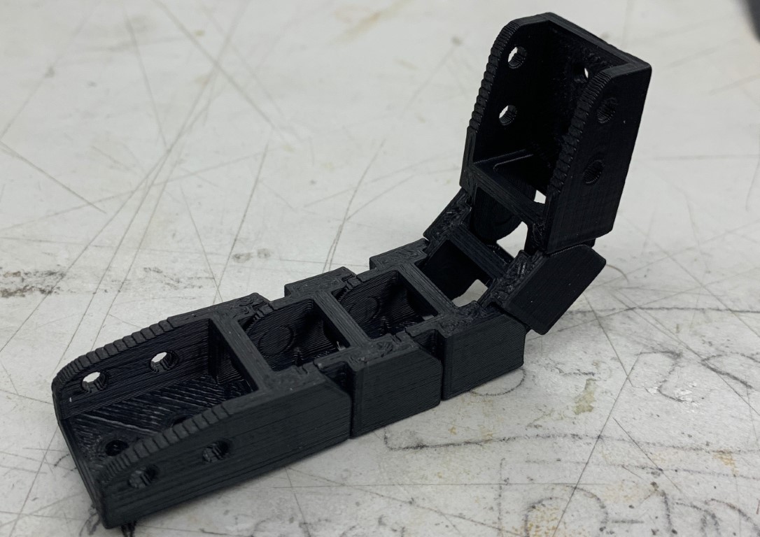
I printed a few pieces in ABS for flexibility and durability and they looked great, so we ended up printing enough as needed to reach to the extremes of the machine.
Cable Chain .STL Files (.zip format)
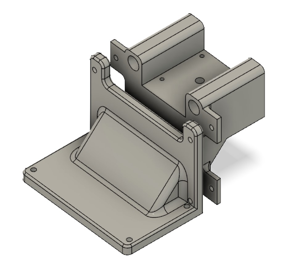
Light Carriage - Maxine
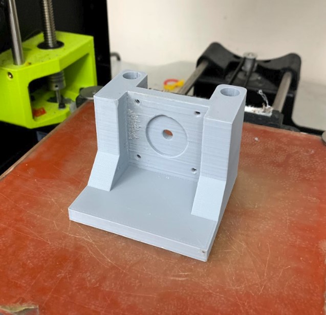
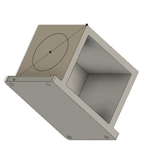
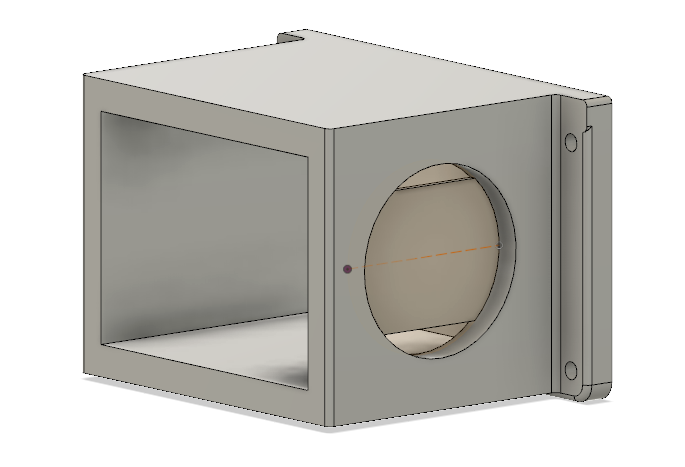
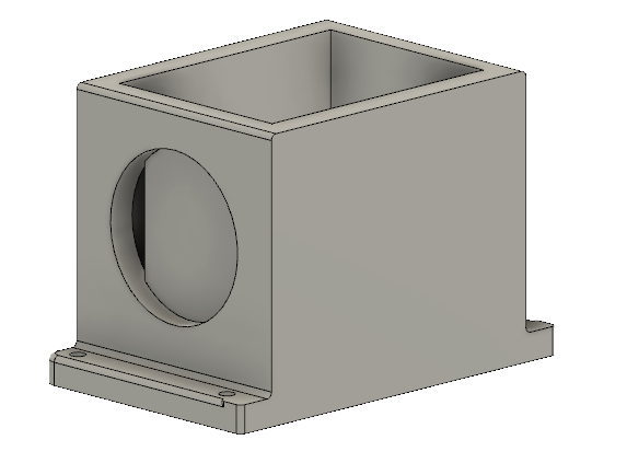
To make the box for the light, I used Will’s original design so that the screw holes would line up. I took one of the bodies that had the screw holes and extruded down to cut, just leaving a base with the screw holes.
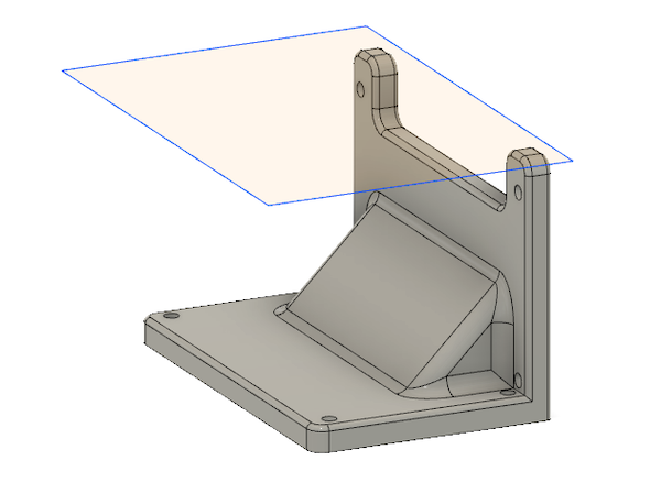
I rotated the base so that it was on its side. Using this as one of the walls, I created a box with each side having a 0.25in thickness. In the center of the front wall, I made a circle, which is where the neopixel would fit.
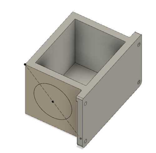
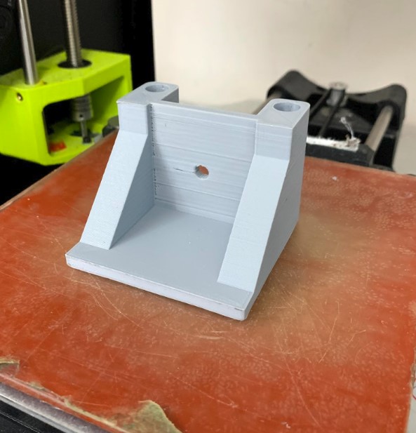
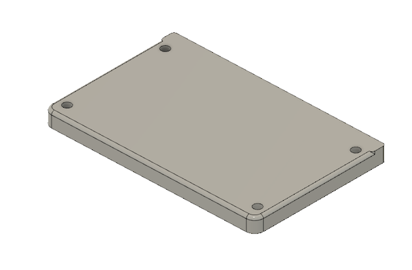
Then, I realized that I needed to print it with the screw holes flat on the bed of the 3D printer (as shown below). So, the opening for where we would put the electronics for the neopixel would have to be on the side (when oriented how it will be when attached to the axes), not on the top. I changed this later on.
3D test
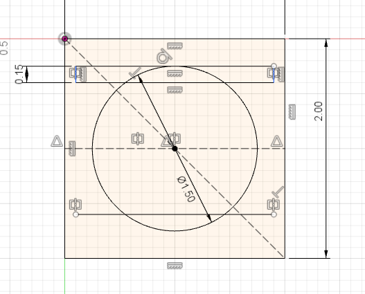
To make the actual hole for the neopixel, I measured the neopixel with calipers, and she found the external diameter to be about 1.4. Then, I measured the distance between the external and internal circle. This was about 0.26.

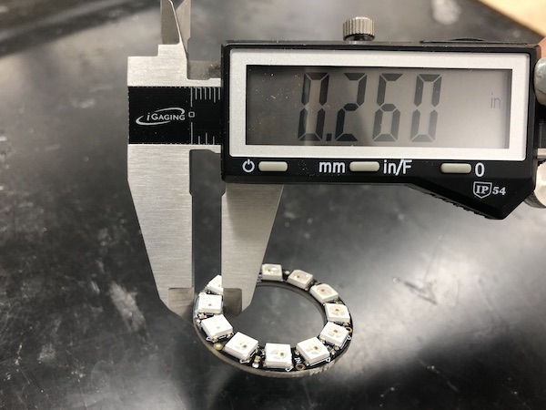
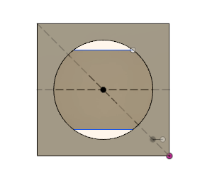
I extruded so that the piece in the back was 0.05 inches and the piece in the front was 0.2 inches. This is what I was planning for the larger model. The cutout is 0.15 inches into the circle from a tangent line.
Download my print test (.stl) Download my print test (.f3d)
The picture of the final 3D printed test:

We soldered a neopixel and put it into the cavity:
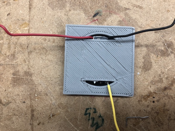
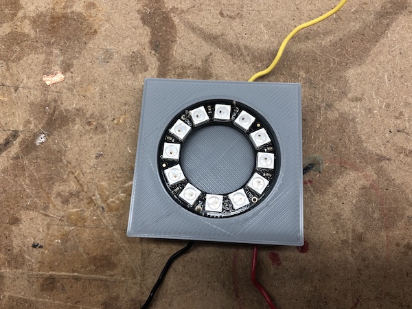
As shown in the picture depicting the back of the neopixel, the cutout wasn’t quite big enough. So, when I went back to the actual design, I changed the size of the cutout from 0.15 inches tall to 0.2 inches.

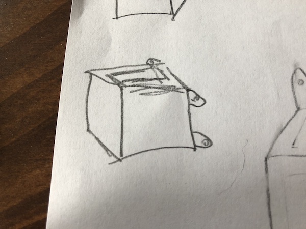
I sketched out a basic idea of the carriage to show to everyone before I designed it:

Then, after looking at the pieces that it’d be based off of (Will’s axes designs), I saw that the screw holes would have to be to the front and back of the carriage.
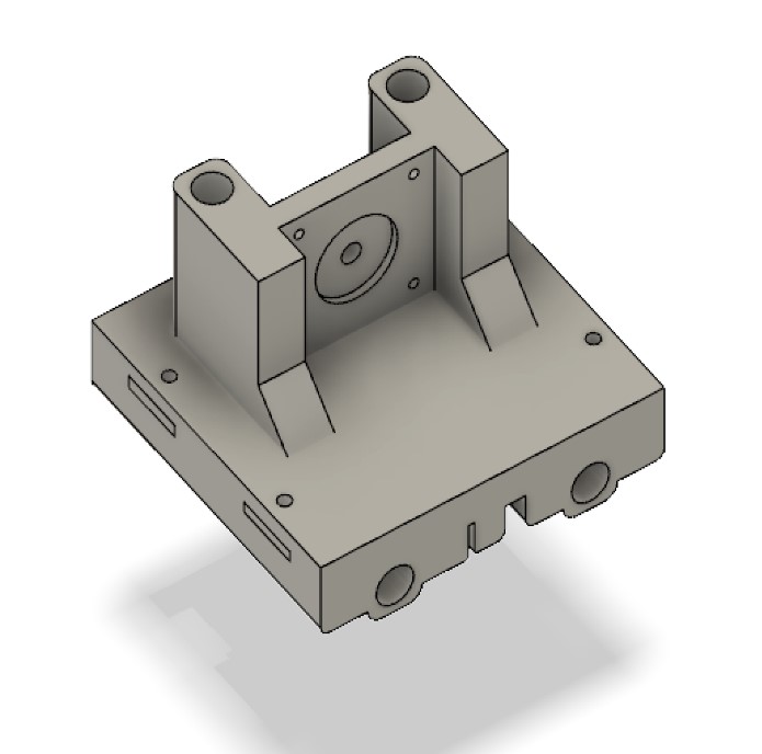
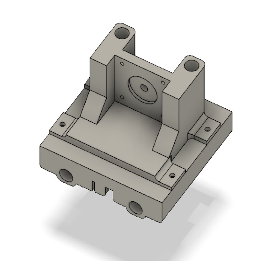
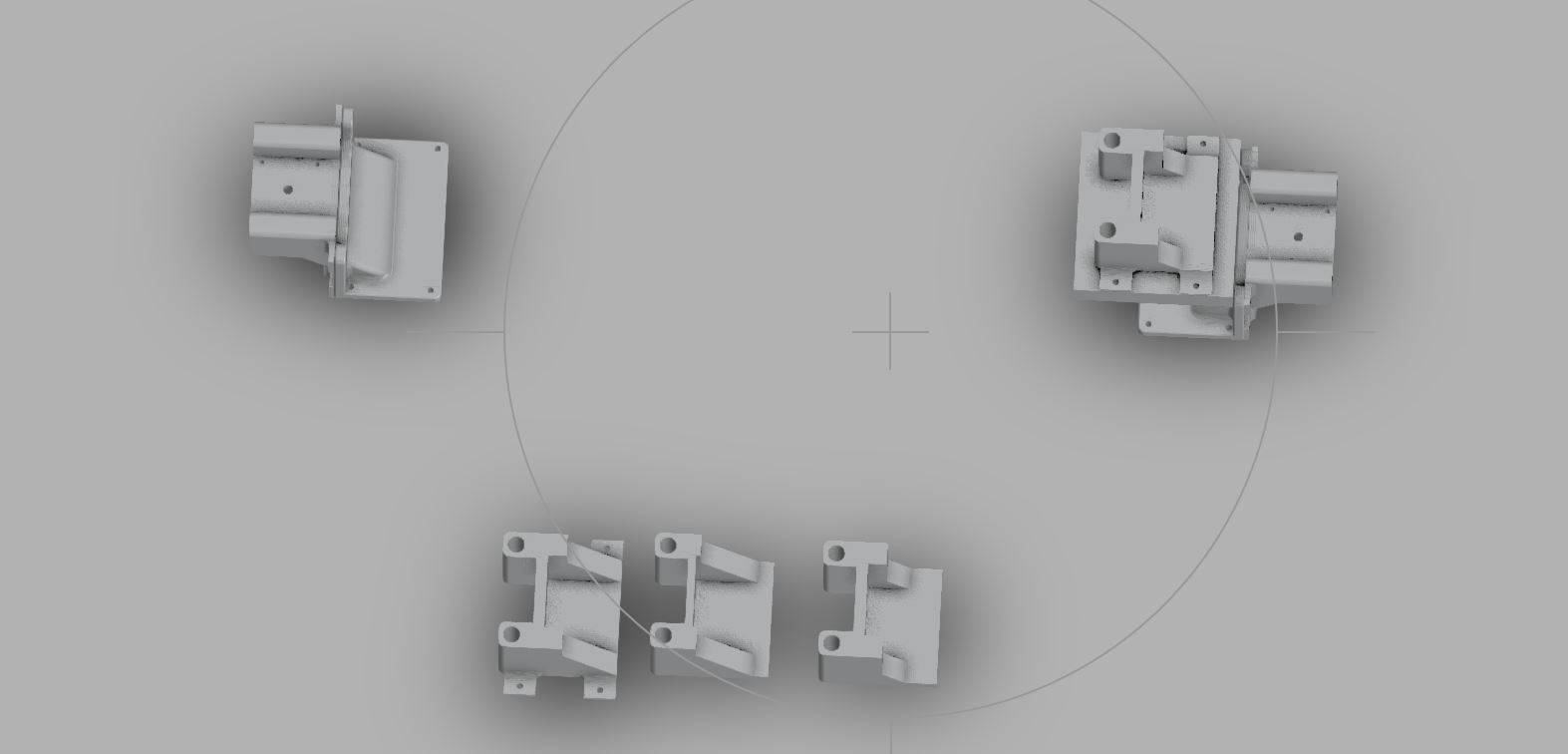
The final Fusion design:
How it will print:
Download my light carriage (.f3d)
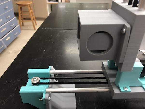
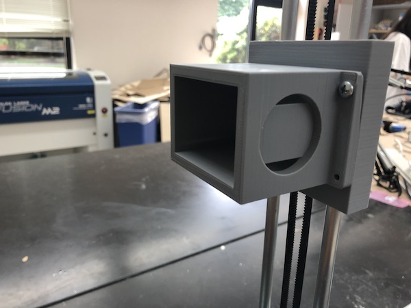
Printed and attached to the axes:
Download all of Maxine’s files
General Frame - Katie
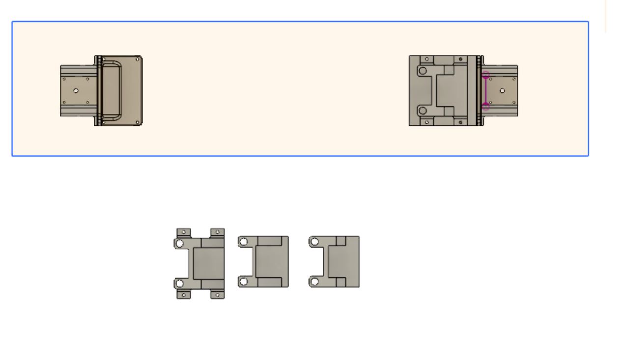
To capture a clear image with our POV machine, I created a frame to act as a backdrop for the light. I started by taking the dimensions of Will’s 3D printed axes parts and the metal rods.
Dimension Estimation
Since the final machine axes was not completely printed/assembled yet, I asked Will to configure his digital renderings in an appropriate distance apart so that I could estimate the box dimensions. My first estimation was 30 inches by 30 inches by 7 inches.
After discussing with Maxine and Kai, I found out that their parts would not be applicable to my design. Knowing this, I still decided to add a few inches for clearance (top/side: 2 inches, ends: 3 inches)
GRBL Research
I decided to research the GRBL software (recommended by Mr. Rudolf) in order to find the approximate amount of space needed for the circuitry.
According to this GRBL github page, GRBL is…
-
GRBL is a software that can control stepper motors via gcode
-
GRBL runs on an Arduino
-
GRBL was created by Simen Svale Skogsrud with the inspiration of Mike Ellery’s Arduino GCode Interpreter
-
GRBL can maintain more than 30kHz step rate
-
GRBL is for three axis machines
I also decided to look into the following sources to learn more about installing and using GRBL.
This video explains the basic premise of GRBL.
To learn how to download GRBL, I watched this video which also explained the process of
Here are the written instructions for the video.
Here is the GRBL zip master file that they mention in the video.
Since both of the above videos mentioned a GRBL shield that you can hook up to an Arduino, I decided to buy one for testing purposes. Here is the shield that I bought. It included the GRBL CNC shield board, an Arduino UNO R3 Board compatible with 4-axis support, 4 A4988 Stepper Motor Drivers, and 4 Heat Sinks.
I looked into DIY GRBL shields as well. Here is a good example of a DIY GRBL shield that I found.
From my research, I found that the involved circuitry for our machine would most likely be a little larger than the size of a Satshakit or arduino. With this in mind, I kept with my previously stated 3 inches of clearance.
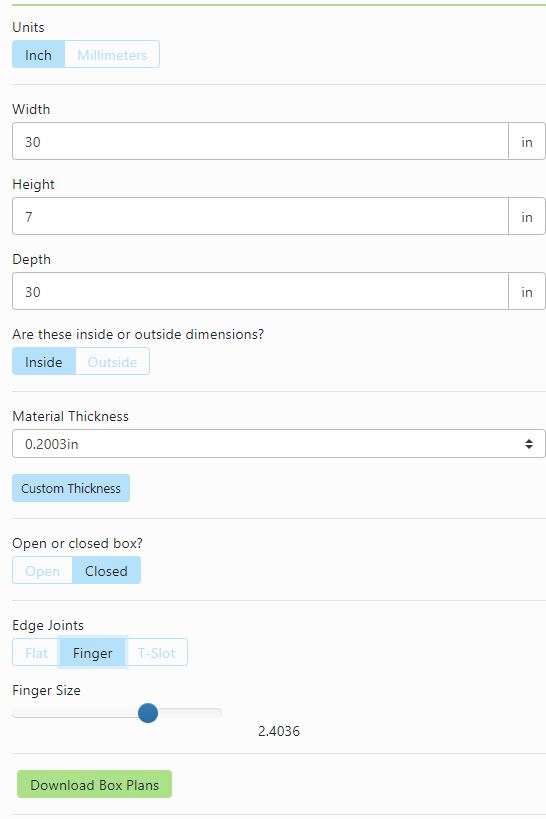
The final dimensions of my box were 30 inches by 30 inches by 7 inches. I checked these dimensions again with the final model to make sure I would be cutting the right sized backdrop box.
Designing the Frame
To design the tabbed box, I used this online resource. Here are the settings that I used.
This is what the box looked like once it was done.
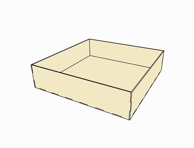
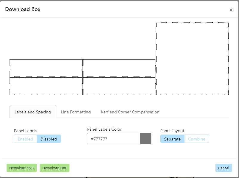
I downloaded the file as a DXF. Here is the fusion file.
Here are the files that I used.
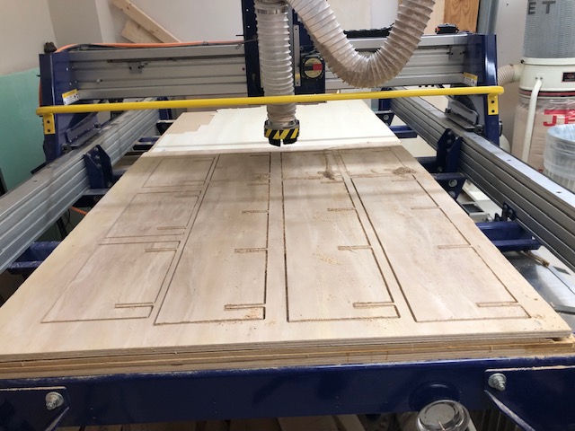
Cutting the Frame
Once all my files were prepared, I moved on to cutting out the wood on the ShopBot. I processed my files on Aspire. Then, I uploaded my toolpaths into the ShopBot software.
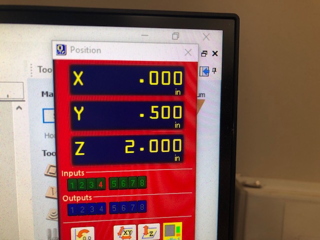
Since the engineering classes at our school are in the middle of final project week, I was not allowed to remove their wood from the ShopBot. Luckily, the person who had used the ShopBot last did not cover the entire table with their wood! With the help of Mr. Dubick, I was able to align the X, Y, and Z axis with the remaining area of the ShopBot.
Here is a picture of my Y-axis offset.
Because of final project week, we also had a smaller supply of wood in the Fab Lab. Mr. Dubick found me two pieces of scrap ⅛ inch wood that I could use. I manipulated me files so that everything would fit on the scraps.
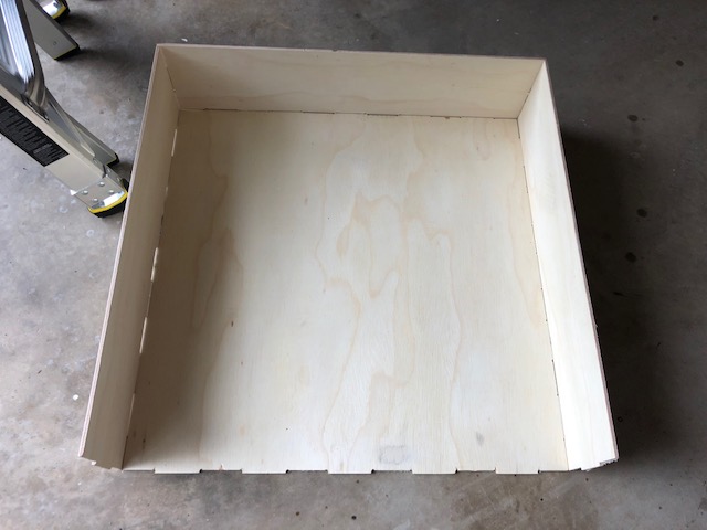
Finally, I was able to cut. I tried to put tabs into my toolpaths, but because the wood was so thin, they didn’t really work. (They held the wood in place, but snapped off easily when we took the finished wood off the table.)
Here is the semi-finished box. (I tried to assemble it as best as I could without sanding it.)
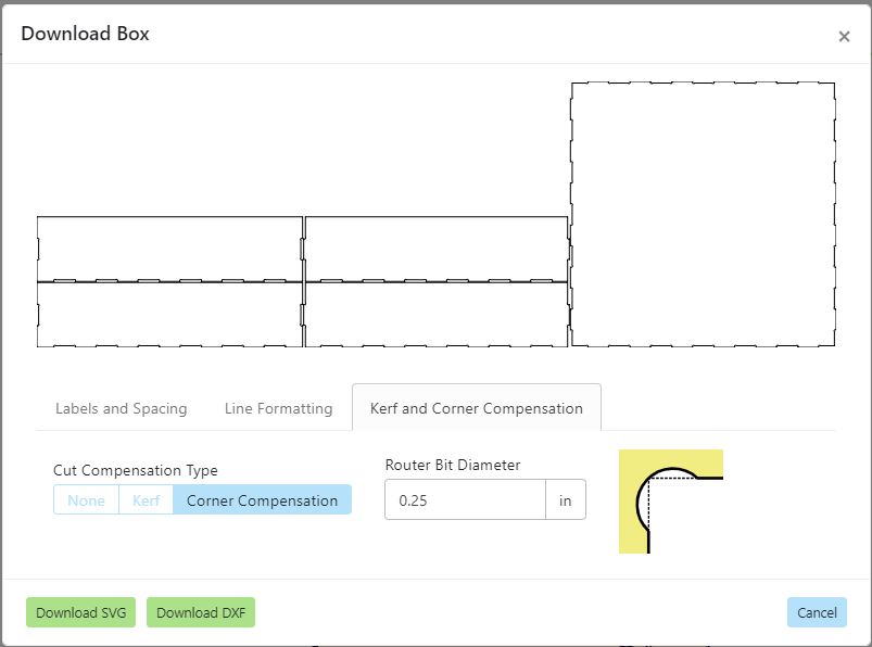
Once I had finished removing the pieces from the ShopBot, I figured out that I had not included dogbones. To fix this mistake, I decided to create DIY dogbones.
Another solution that I could have implemented from the beginning was using the corner compensation tool to implement dogbones into the design.
This is the fixed file.
Post Processing the Frame - Kai, Katie, Maxine, Will
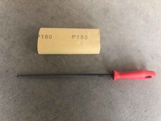
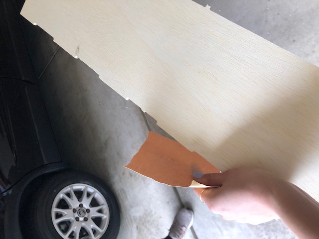
To create the DIY dogbones, we used a circular file and sandpaper. (We mainly used the sandpaper to smooth the edges of the wood to prevent splinters.)
Sanding the Frame - Kai, Katie, Maxine, Will
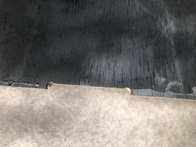
To add in the DIY dogbones, we used a circular file.
Here is what they looked like once they were filed.
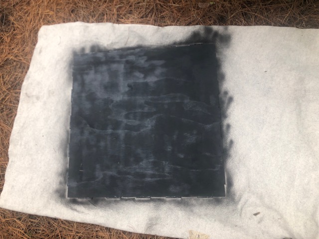
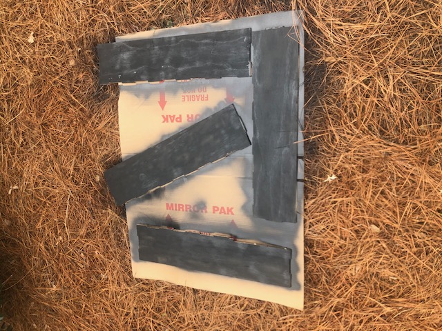
Painting the Frame - Kai
In order to create a stark contrast between the light and the box, we decided to paint it black using spray paint.
Above, you can see me spray painting.
Here is the finished product.
Gluing the Frame - Katie
Once Kai was finished spray painting, I worked on gluing the background box together. I used wood glue to secure the sides together and tables to prop up the drying pieces. I noticed that the wood glue had clumped up at the seams of the box, so I wiped them clean. Still, the yellow wood glue was mildly visible against the black paint, so I decided to come back (once it had dried) to paint the seams with black acrylic paint.
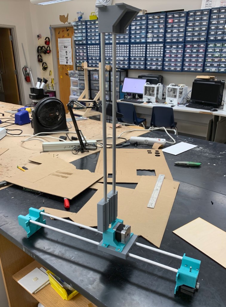
Testing the axes & long-exposure view - Kai, Maxine, & Will
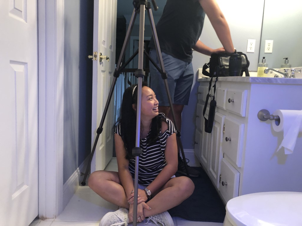
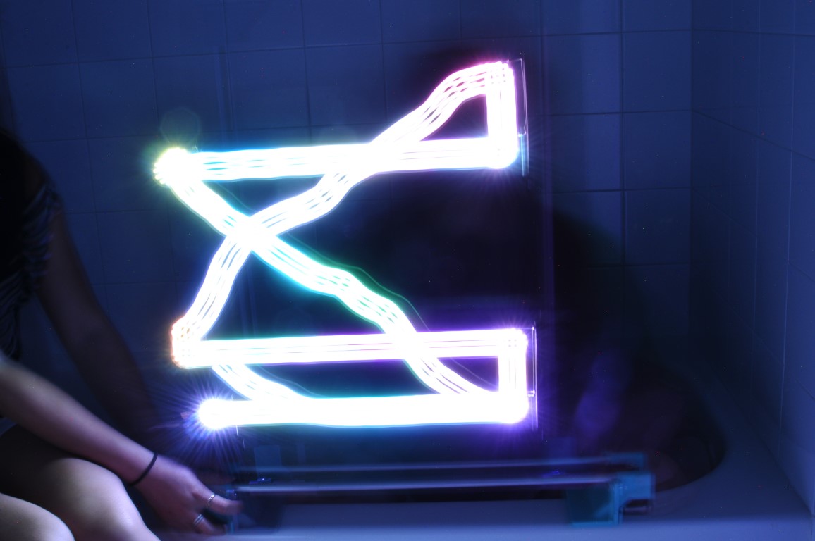
While I, Kai, set up my camera (see above photo; not sure why Maxine was so excited, nor why she chose to sit under my tripod) for the long-exposure shots in a window-less bathroom so that we wouldn’t have any external light, Maxine & Will hopped in the bathtub at the opposite end of the bathroom and held our contraption up without the box so that it would fit in our limited space and so that they could move the axes from behind the machine.
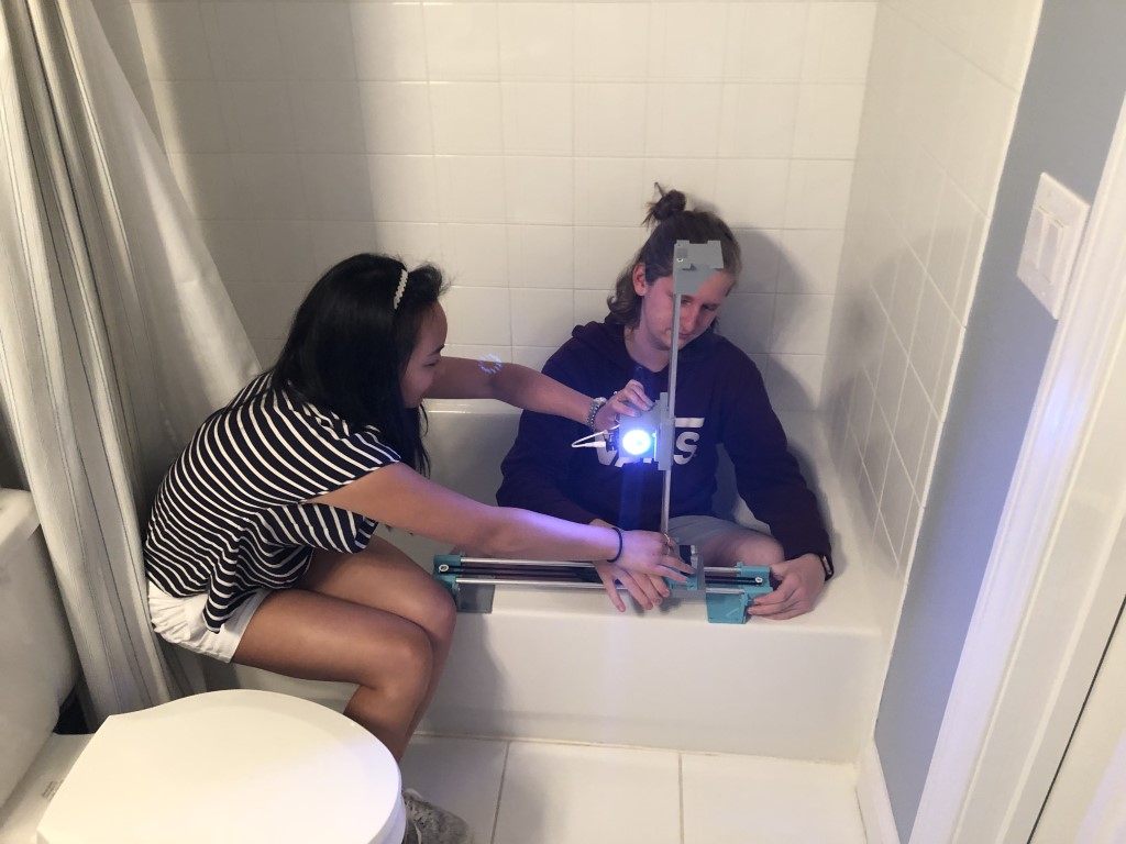
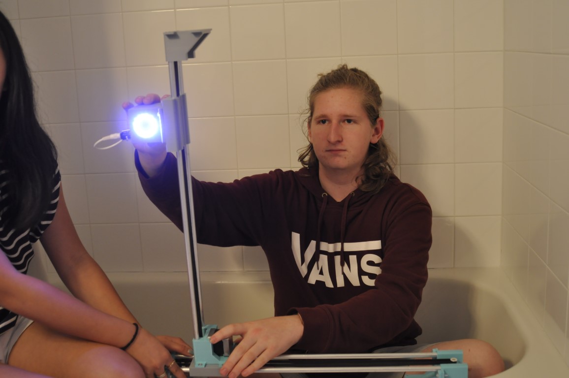
Once I was satisfied with how the shot looked from my point of view, we turned off the overhead lights and hooked up the Neopixel. I took two 30-second shots while Maxine and Will moved the light around on the two axes. Below, you can see the results. Note that some of the light appears jarred, which is because the light was being moved in two directions manually, which is hard to do in itself, let alone while inside of a bathtub.

Our Slide
Our Video
Potential Iterations
-
Axes are over constrained (explanation)
-
Redesign cable track?
-
Design a piece that attaches the cable to the box (instead of hot glue)
-
Design bolt piece
-
More easily removable light
-
Look at datasheet of neopixel
-
Clip in neopixel (would not have to rely on soldered wire, possibly tabs)
-
Threads should not line up - one hole has to be larger, one has to be smaller
-
Brass fitting melted into PLA for threaded holes, screwing everything together
-
Braces on the corners and edges (3D printed)