17. Machine design
This week’s assignment:
Group Assignment:
Actuate and automate your machine
Document the group project and your individual contribution
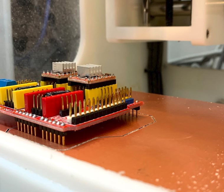
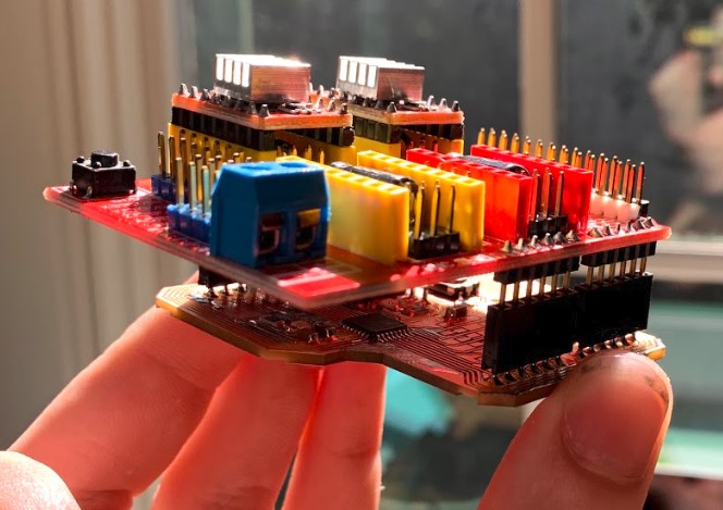
This week, we continued with our machine development. We decided to work with a CNC shield and an adapted Satshakit.
Designing Adapted Board - Will
Here is a board that Katie found that is compatible with the CNC shield.
Making the Board Design
At first glance, my assignment for this week may seem pretty similar to what I have done with the satshakit last week. The reality is that for last week, I only had to add to the board, not rearrange what was already there. This week, I have to relocate allot of the parts for the board, so things could get tough.
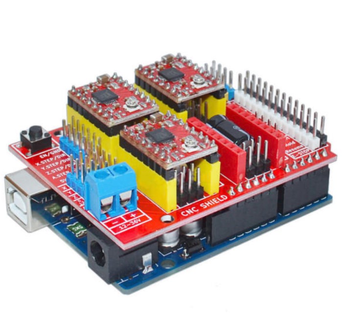
Here’s what the shield looks like.
First of all, I wanted to go over the pins that the shield would use compared to the pins that a satshakit has to offer. A few things I found were that the satshakit doesn’t have an AREF pin for the analogue voltage, it doesn’t have a 3.3 Volt output, and it doesn’t have nearly as many ground pins. However, after some consideration I figured that the shield won’t use the 3.3 volt pin for anything, and that the ground pins would be easy to relocate, so that wasn’t too much of a concern.
That left me with the AREF pin. After looking around online some, I found that the aref pin is used to supply a reference voltage for any analogue signals. I then looked at the eagle board file for the original arduino and saw that on the arduino, they have a line going from P20 on the chip straight to the pin header.
Since I’m using 5V to power the board, that means that all I have to do is route P20 from the ATmega chip over to the AREF pin just like on the actual arduino.
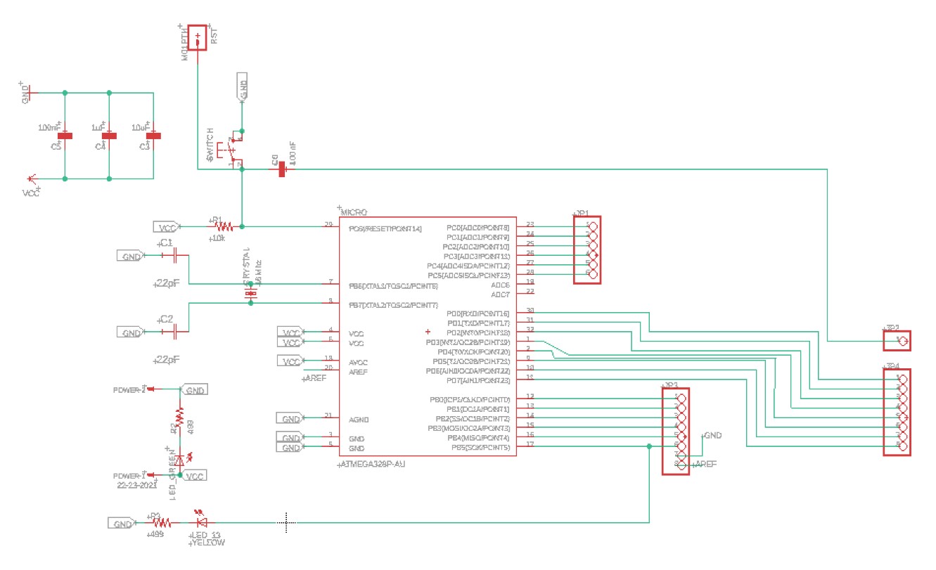
I made these changes to the schematic, and I also changed some of connections between the atmega pins and the headers to match the configuration of an actual arduino.
Then, Katie found a board design here that was made to fit any arduino shield as well, so I looked at it too to see how I might could use it to help me with my own board design. The only issue I had with the board really was how many through hole components there were on it, I knew that would never work for one of our fab academy boards.
I pulled up the eagle schematic for this board too, just to see what the spacing for the arduino headers looked like.

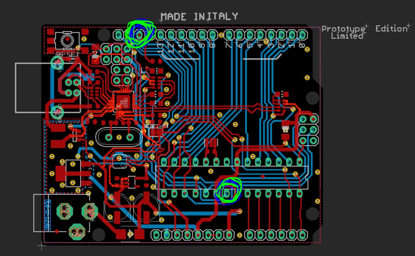
Next, I started arranging the pins on my board file to match those of an arduino.
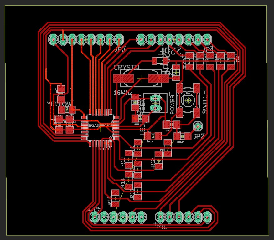
I’m coming back to this after some more time with the board, and this is where I’m at now.
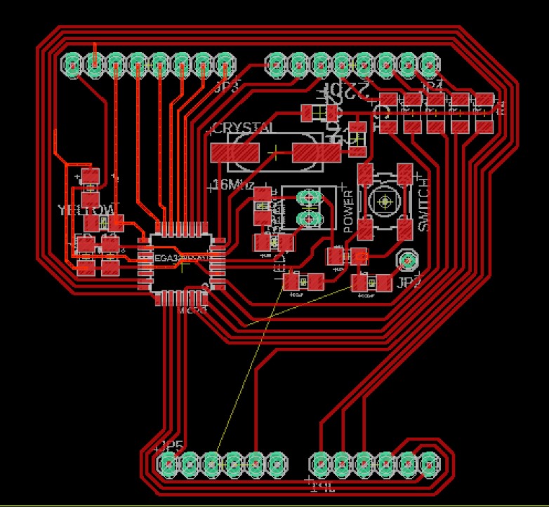
I still have those two wires that just don’t ever seem to be able to work. I think at this point I might do something a little unorthodox. Rather than working around the board more and trying to find the most efficient route, I think I’ll just put in a lot of jumper resistors because I have to get this done, and that’s what’s going to work right now. I dropped some plain resistors into the schematic without making any connections, then I added those into the board in the right places, but without any connections made yet.
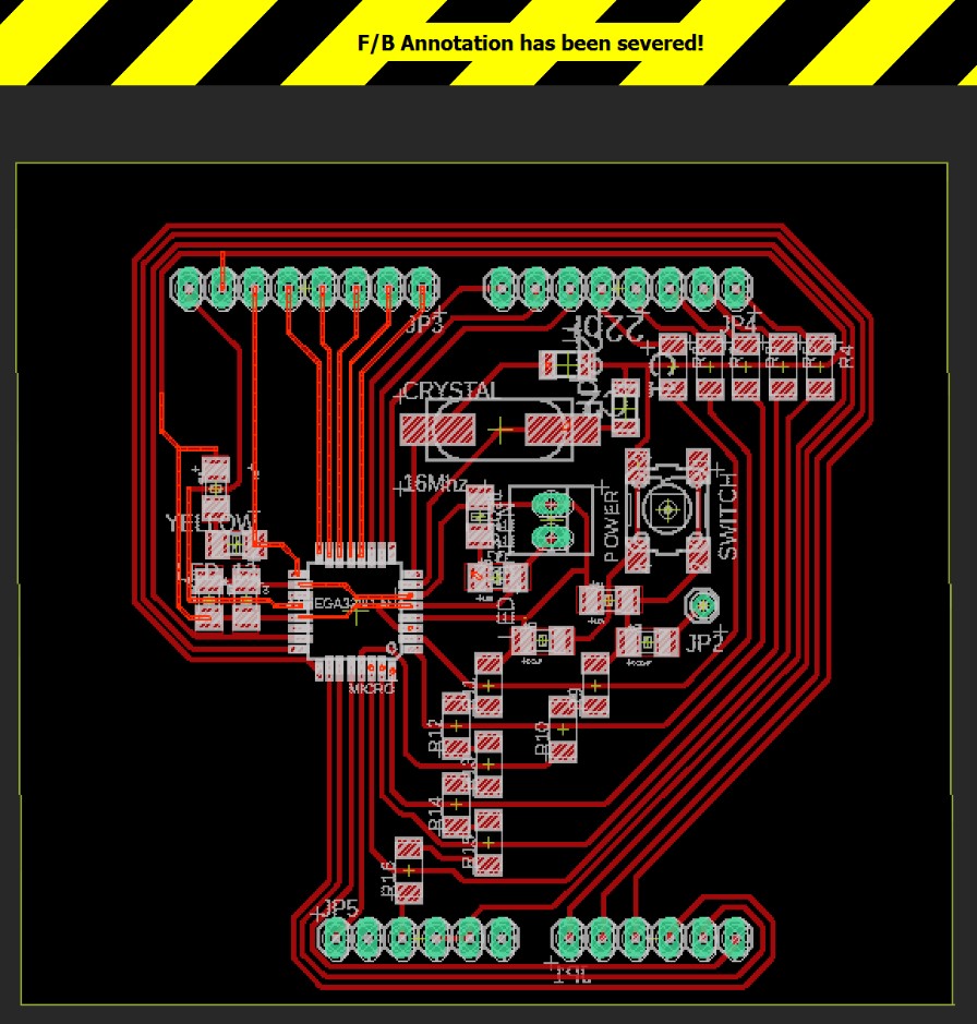
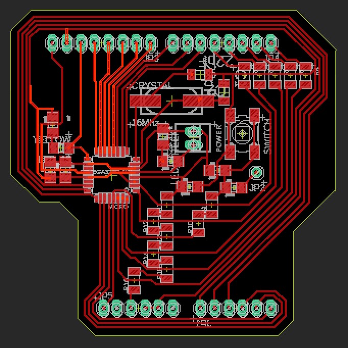
Next, I closed the schematic file and severed the forward/backward annotation so that I could connect the jumper resistors without eagle getting mad at me about making connections that havent been pre set in the schematic. I then drew in the signal connections and connected the routes through the jumpers correctly.
Then, I closed off the dimensions of the board and saved the file one last time.
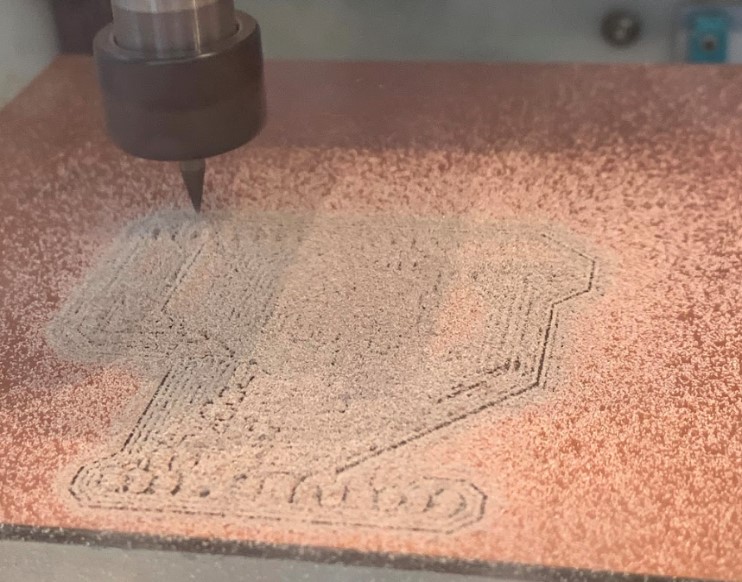
Making the PCB
The board fabrication this week wasn’t too bad, there were just a few more complications than usual along the way.
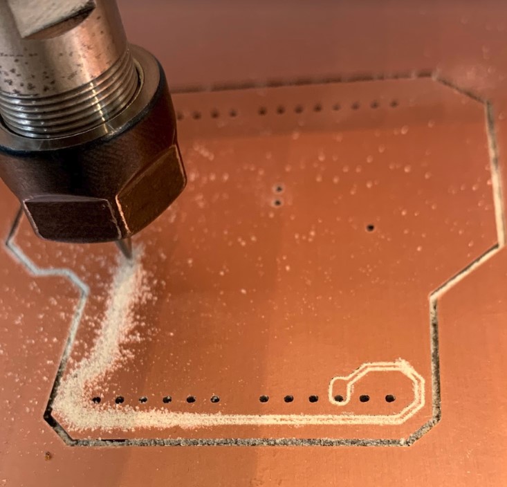
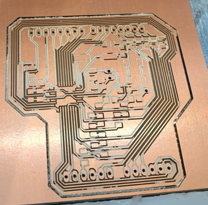
The first board that I milled went smoothly, here are a few pictures from that process.
Thankfully, I decided to check the spacing of the pins on the board before I started soldering all of the components, and that led me to discover this little problem here.
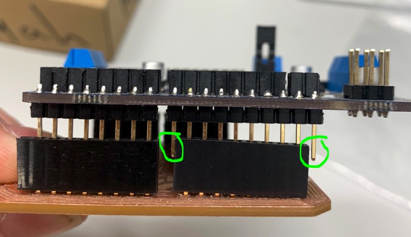
These two pins don’t line up correctly on the board, which meant that my spacing was off somewhere in the board file. I went back into the file to check it and I discovered that I had placed the two headers about .040 inches too far over. I corrected this error, then I went back to the milling machine to cut out another board.
This time, I cut out the pin holes first to check and be sure it would all line up right.
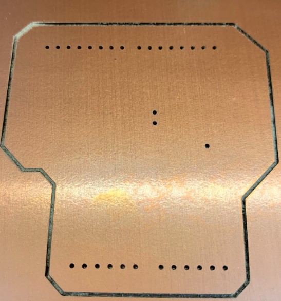
Thankfully, the board fit in correctly.
I went ahead and started milling the traces then, but something was wrong with the machine, because it didn’t start back in the right spot.
I checked out all of the machines parts until eventually I found that one of the two belts on the router had broken, causing it to be loose.
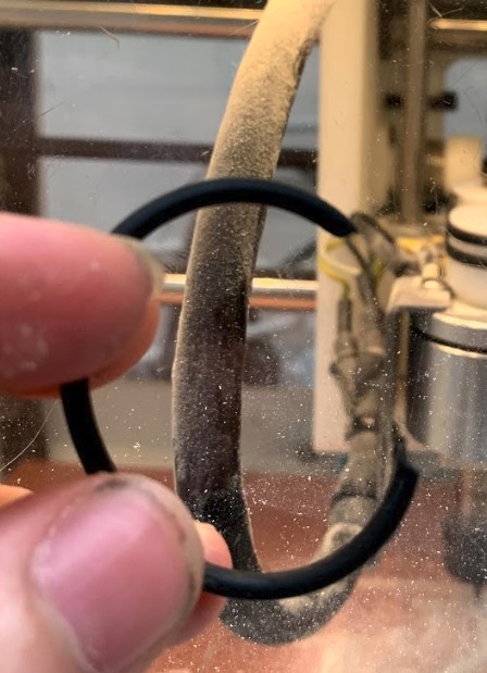
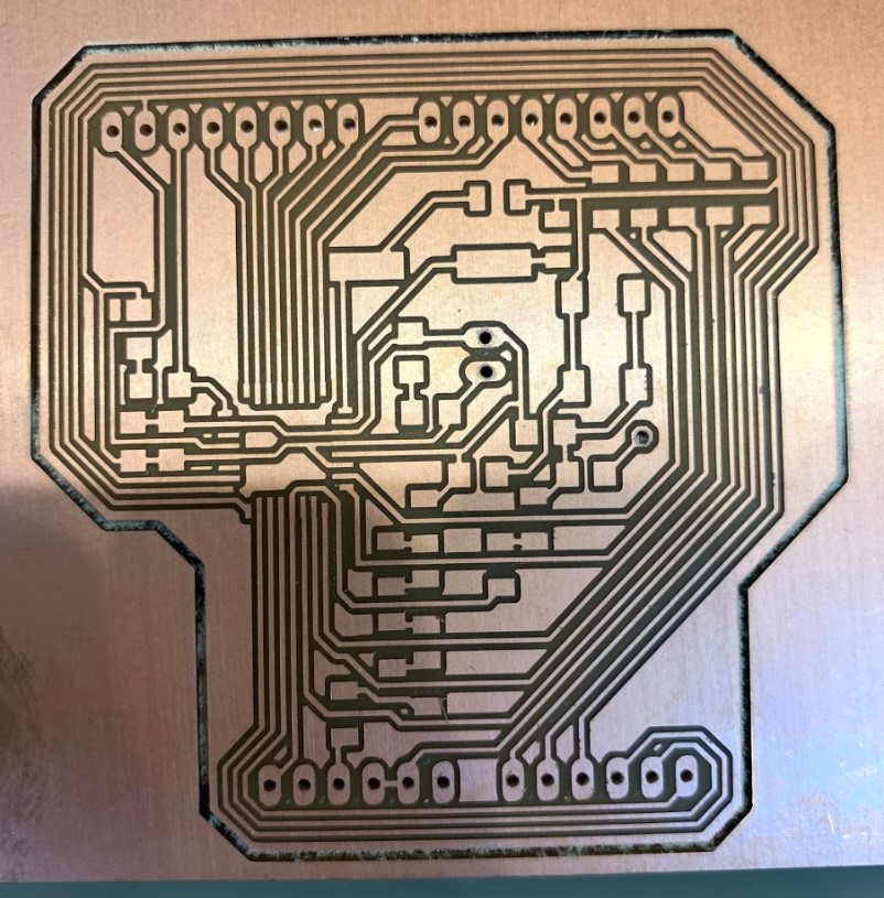
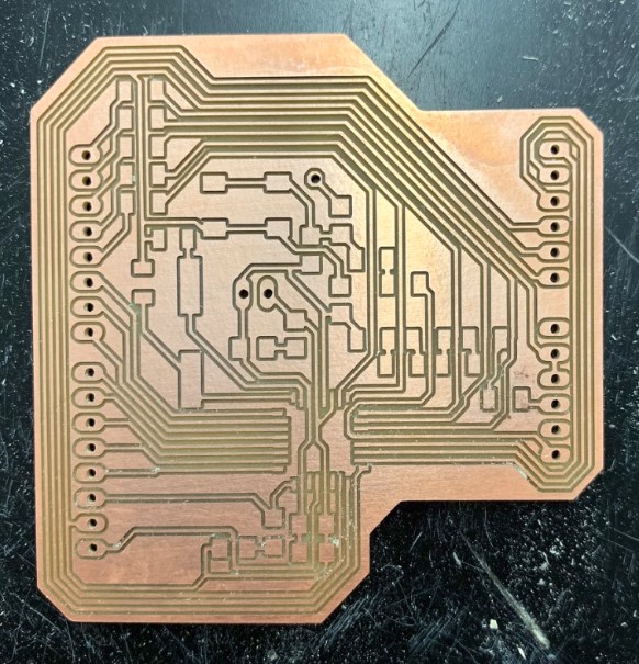
This was an easy fix, and before long I was back to milling again on a clean board.
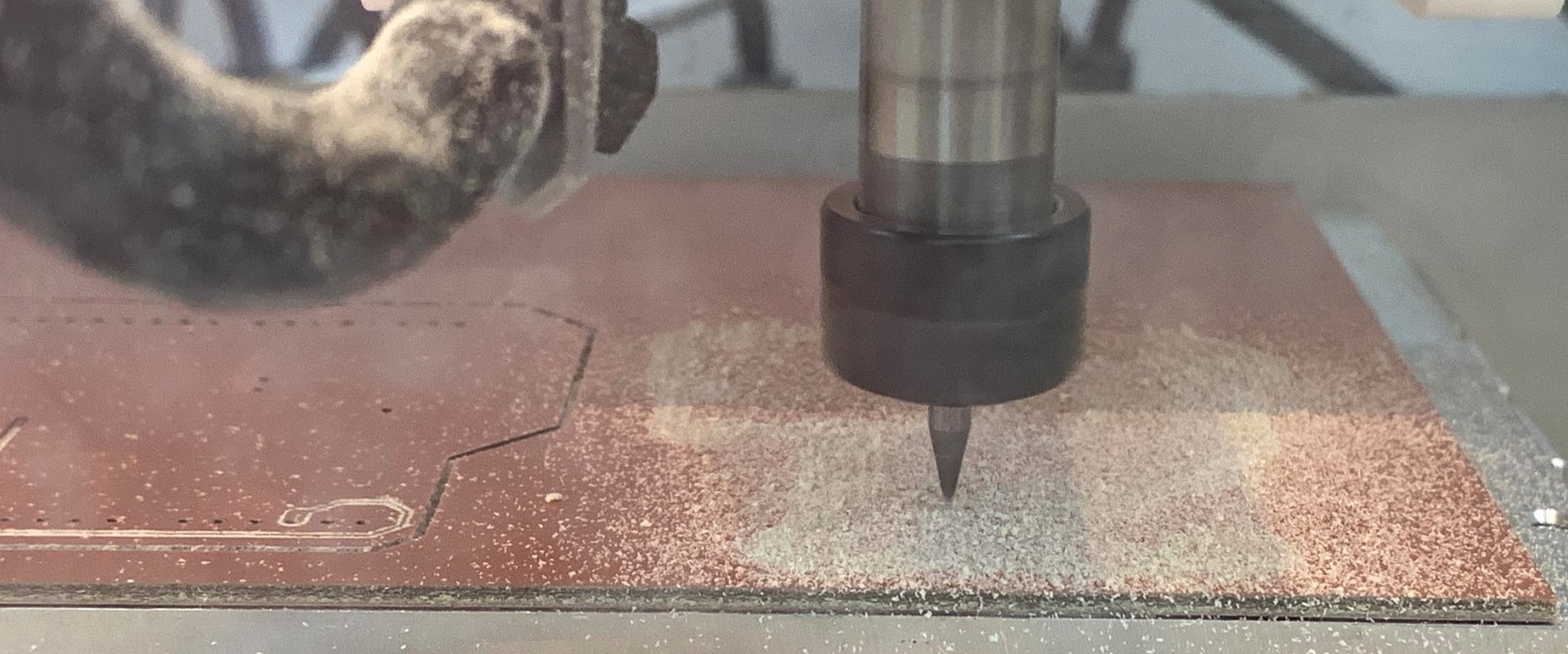
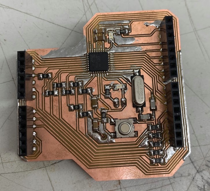
Then finally, the pcb was ready.
Fixing the Board
At this point I realized that because I had milled the board out on double sided pcb, the pins of the headers poking through the bottom of the board would all short circuit each other because they were all touching the saem single layer of copper.
Mr. Rudolf had a good idea for how to fix this. He ended up using the table saw at about 1/32nd of an inch to cut out little channels along the bottom of the PCB, removing the copper that was in the way but leaving enough PCB behind to keep the board stable.
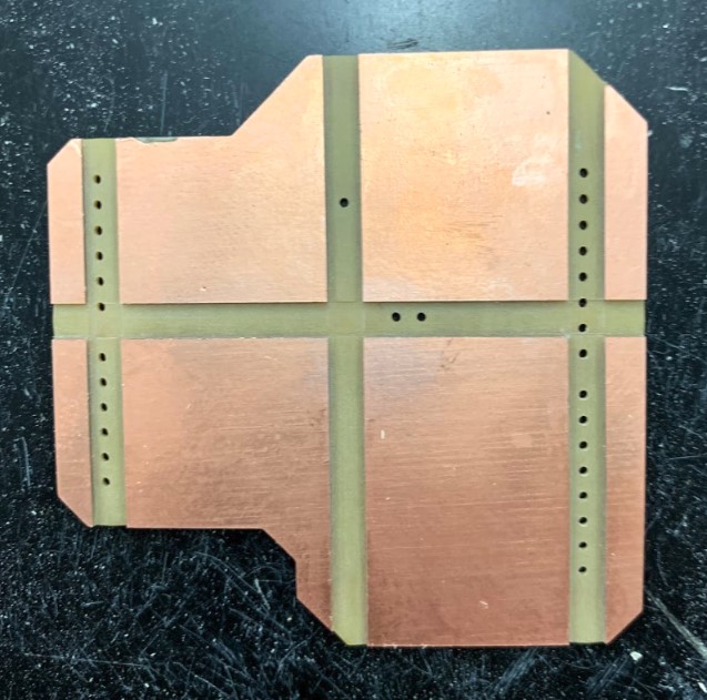
With that, I had my board all finished and ready to solder.
Soldering
Soldering was pretty much the same as it always is, I got the board taped down, I put on most of the components, then I had to somehow solder the headers on. Since I wouldn’t be able to solder the headers on from the bottom due to the lack of copper, I had to somehow hold the headers up on the top of the board so that I could get my soldering iron in there and secure the component.
I ended up using a normal arduino underneath my board with the headers on top of both to keep the spacing just right.
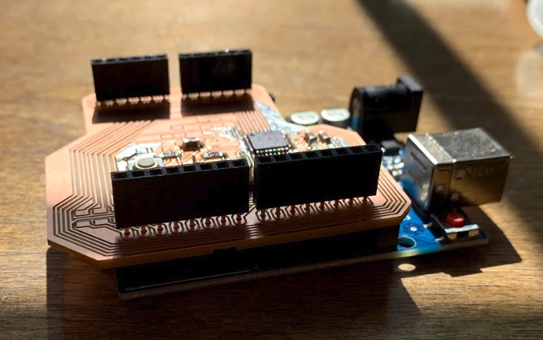
This worked perfectly, and the shield fit on just right.
After finishing that up, I realized that I had forgotten some of the components in the lab before leaving, so I would have to finish up the board the next day.
After I came back in the next day, I gathered the rest of the components and got the board finished up.
Programing
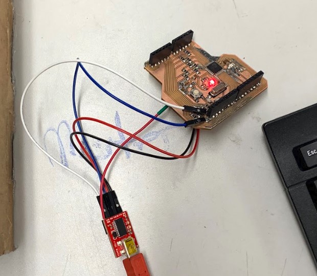
Once the board was all done, I got it hooked up to my programer and computer, then I burned the arduino bootloader onto it.
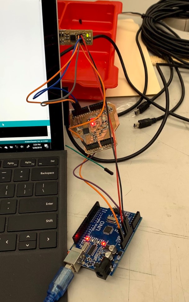
This went well, so then we uploaded the Gerbil library onto the board from another computer that already had the library on it.
With that, we were ready to hook it up to an FTDI cable and control our machine!
Meanwhile, Kai, Katie, and Maxine worked on setting up the shield, motors, and motor drivers.
To set up everything, we walked through this tutorial that Katie had started during the previous machine week.
Power Supply - Kai & Katie
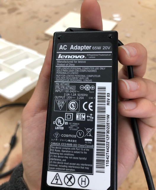
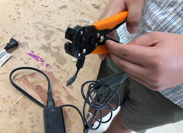
To get the correct power supply for the motors, we used an old Lenovo laptop 20V power supply no longer needed in the Lab. With Dr. Harris, we stripped the cord to work with our board. We had to make sure to connect the right wires because if we made a mistake, the connection “could melt things” (Dr. Harris). And melting is not good. So, we looked at the specs listed on a sticker on the power brick.
Kai stripped the wires while I researched the chord specs and power supply of the board.
Here are the chord specs.
Here is us stripping the power supply.
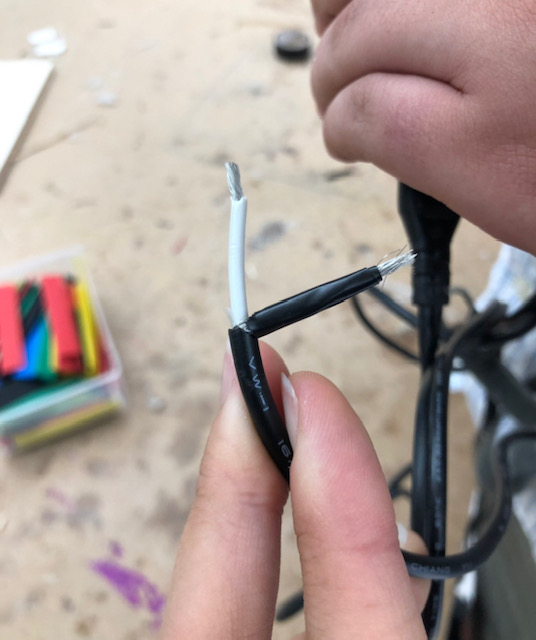
Knowing that the ground was on the outside of the cable and power on the inside, we inserted the wires into their respective receptacles on the motor shield and screwed them down.
Uploading GRBL - Kai & Katie
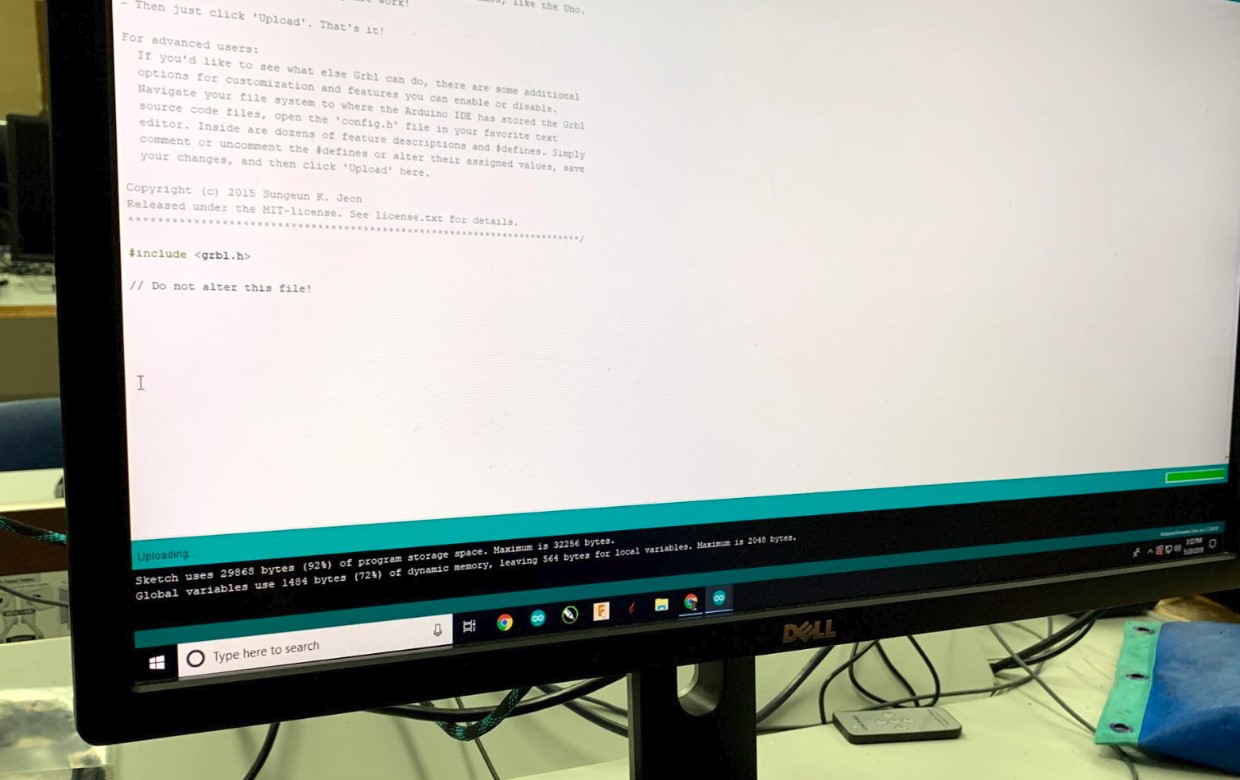
After creating the power supply chord, we moved on to download the GRBL firmware onto the Arduino. I downloaded the GRBL library last week, so all I had to do was upload the example file onto the board.
Here is the example file.
/***********************************************************************
This sketch compiles and uploads Grbl to your 328p-based Arduino!

To use:
- First make sure you have imported Grbl source code into your Arduino
  IDE. There are details on our Github website on how to do this.

- Select your Arduino Board and Serial Port in the Tools drop-down menu.
  NOTE: Grbl only officially supports 328p-based Arduinos, like the Uno.
  Using other boards will likely not work!

- Then just click 'Upload'. That's it!

For advanced users:
  If you'd like to see what else Grbl can do, there are some additional
  options for customization and features you can enable or disable.
  Navigate your file system to where the Arduino IDE has stored the Grbl
  source code files, open the 'config.h' file in your favorite text
  editor. Inside are dozens of feature descriptions and #defines. Simply
  comment or uncomment the #defines or alter their assigned values, save
  your changes, and then click 'Upload' here.

Copyright (c) 2015 Sungeun K. Jeon
Released under the MIT-license. See license.txt for details.
***********************************************************************/

#include <grbl.h>

// Do not alter this file!
Within the GRBL folder, there were two types of files, ‘c’ and ‘h’.
C - code H - header (“include” functions)
Mr. Rudolf explained to me how the file that we had just uploaded basically contained all the commands that GRBL would call.
Control Methods
ChiliPeppr Interfacing - Kai
To begin interfacing with our Arduino & motor shield, we decided to use ChiliPeppr’s GRBL Hardware Fiddle. To do so, I first had to install their Serial Port JSON Server to be able to communicate with the Arduino via serial on the ChiliPeppr website. Once I had the server installed and running, I opened ChiliPeppr, followed the prompts to connect to the server, and connected to the Arduino port.
Setting up the GRBL Shield - Kai & Katie
We initially decided not to use microstepping in the setup phase of this because we literally just wanted to test that the motor works (though we shortly enabled full microstepping, which on this shield was 1/16). We didn’t use end stops because we just wanted to get the motor working.
We tried to run the motor as a test. We could tell that something was happening because it made a sound, but we weren’t sure what was happening. Turn up the volume to hear the noise:
We thought that the friction caused by the belts caused it to not work, so we tried to change the current adjustment screw. Both Kai and I tuned the screw, but I ended up making a majority of the adjustments while Kai read the multimeter.
We referenced this website to tune the current adjustment screw.
Here is a video of me tuning the screw.
This is the screwdriver that we used to tune the screw.
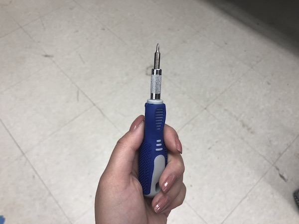
This still didn’t work. To test the shield and eliminate the friction that the stepper motors may be experiencing due to the belt, we hooked up the shield to another stepper motor that we had. When we did this, that stepper motor worked completely fine.
Testing one of the other motors with the driver and ChiliPeppr:
It was at this point that we deduced that the motors we had installed on our machine were broken. We then found two identical motors in working order and installed those. No surprise, those motors worked instantly.
Once we knew we had working motors, it was time to begin tuning the machine. To do so, we needed some information about our motors. We found the datasheet of the motors that we’re using.
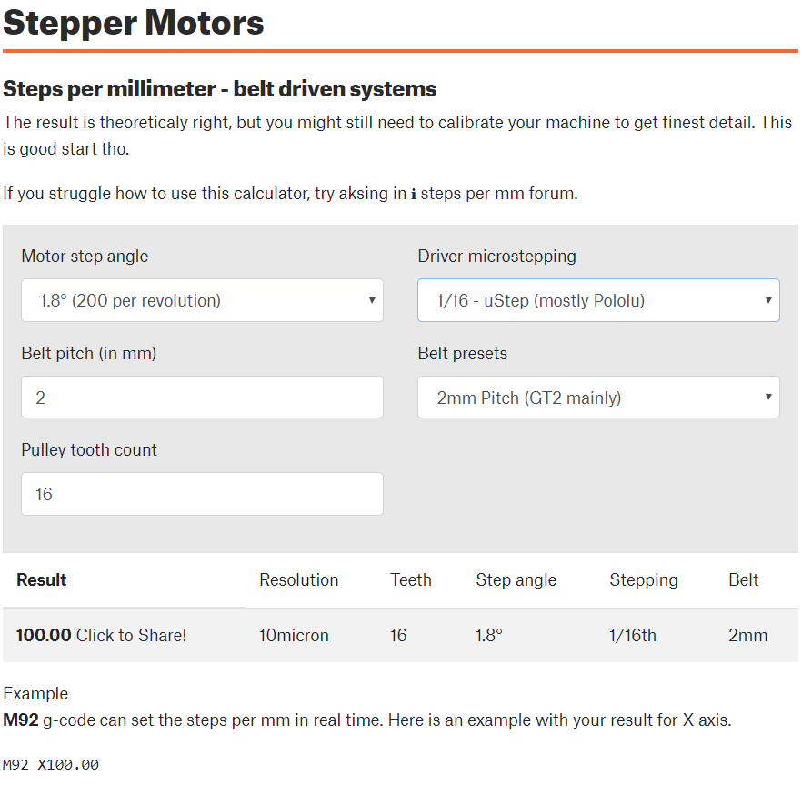
We used this calculator to calculate steps per mm, since the data sheet didn’t have this information.
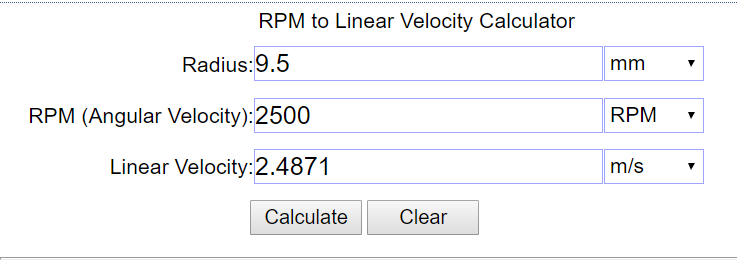
We also used this calculator to convert RPMs listed in the datasheet to linear velocity. We needed this info to correct the GRBL settings of steps/mm for X & Y axes, X & Y max rates, and X & Y acceleration rates.
Our final GRBL settings values are as follows:
$0=10 (step pulse, usec)
$1=25 (step idle delay, msec)
$2=0 (step port invert mask:00000000)
$3=0 (dir port invert mask:00000000)
$4=0 (step enable invert, bool)
$5=0 (limit pins invert, bool)
$6=0 (probe pin invert, bool)
$10=3 (status report mask:00000011)
$11=0.010 (junction deviation, mm)
$12=0.002 (arc tolerance, mm)
$13=0 (report inches, bool)
$20=0 (soft limits, bool)
$21=0 (hard limits, bool)
$22=0 (homing cycle, bool)
$23=0 (homing dir invert mask:00000000)
$24=25.000 (homing feed, mm/min)
$25=500.000 (homing seek, mm/min)
$26=250 (homing debounce, msec)
$27=1.000 (homing pull-off, mm)
$100=100.000 (x, step/mm)
$101=100.000 (y, step/mm)
$102=250.000 (z, step/mm)
$110=2500.000 (x max rate, mm/min)
$111=2500.000 (y max rate, mm/min)
$112=500.000 (z max rate, mm/min)
$120=40.000 (x accel, mm/sec^2)
$121=40.000 (y accel, mm/sec^2)
$122=10.000 (z accel, mm/sec^2)
$130=200.000 (x max travel, mm)
$131=200.000 (y max travel, mm)
$132=200.000 (z max travel, mm)
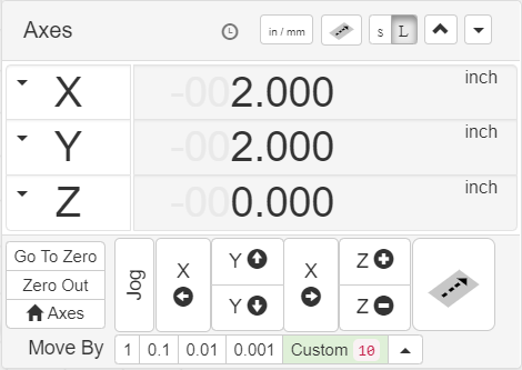
To begin testing the motors, I used the Jog function in the Axes panel.
Click Jog (“It’s supposed to be moving right now but it’s not.” - Kai Vincent)
In this panel, I was also able to change units from mm to in, zero the axes at their home position (for our machine, this is the bottom left corner of the machine), and send the machine to the home position.
Returning to (0,0):
Manual G-code - Maxine & Katie
Since Kai worked on ChiliPeppr, we looked into simple G code to make a circle by using this calculator.
Maxine and I both researched the commands for serial moniter G-code, but I typed them all in.
It gave us this:
G00 Z1 F70
G00 X-4 Y0 F70
G01 Z-1 F50
G02 I4
G00 Z1 F70
G00 X0 Y0 F70
M30
We saw that a lot of this G-code didn’t apply (since we don’t have a Z axis and we didn’t want it to travel to the negative part of the axis that doesn’t exist), so we scrapped it and just started to write straight G-code using this website as a reference.
| Command | Explanation |
|---|---|
| G20 | change from mm to inches |
| Fn | set feedrate |
| G0XxYyZz | Move |
To move the light box, we used the following code. X2 and Y2 tells the carriage to move to (2,2). If we had defined an Zz, it would not have affected the movement of the machine at all because we just don’t have a Z axis; we do not have anything plugged into the Z axis section on the driver. Then, F defined feed rate at 70 rpm.
G0X2Y2F70
A video of it working:
Circle
We tried to make a circle next, but we had several errors.
G2X3Y3F70
This code didn’t work and yielded the error Invalid gcode ID:26. We then realized that we should use the following code:
G2I3J3F70
We thought that using I and J would set the center point of the circle, therefore indirectly setting the radius/diameter. Unfortunately, this code didn’t work. After consulting the G-code reference sheet, we saw that Ix and Jx would designate a center point position of the arc. Since we didn’t specify Xx and Yy, we tried to have it return to its original starting point. It gave us different error messages in the Serial Monitor when we typed in the above G-code, so we consulted this resource to find out what the error messages meant. We also referenced this source for grbl commands (thinking that it was possible that grbl G-code commands were slightly different), but these commands seemed to be the same as normal G-code commands.
Easel - Maxine
After our failed attempt at circles in G-code, we researched Easel. Using Easel, we were able to draw various things, including a circle!
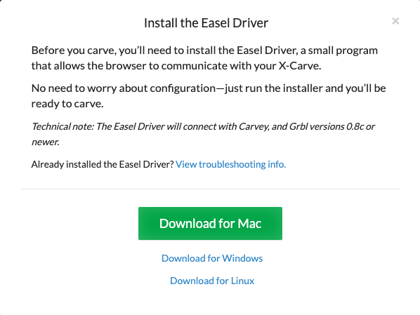
I went through the installation process of Easel, which was quite straightforward. I had to download a driver onto my laptop, and I made sure to get the Mac version.

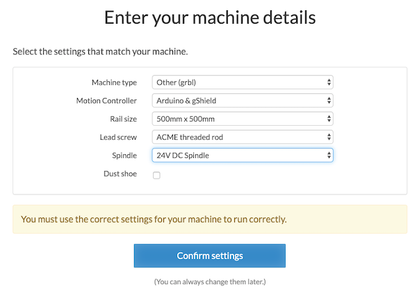
When it asked me about the machine I was using, I made up some of the details. For example, we don’t actually have a spindle. I set the rail size to 500mm x 500mm because it was closest to what we are actually using (something around 16in x 16in).
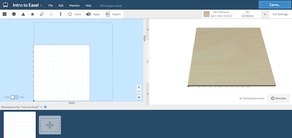
Easel is extremely user friendly, so much of the controls are self explanatory.
What the workspace looks like:
Once I was inside the workspace, I changed my material properties to fit the size of our axes:
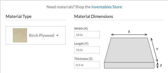
When I drew things in the workspace, I changed the thickness so that the machine would only go over that area once. I also made sure to make things on outline so that it would create an outline and not a pocket cut kind of command.
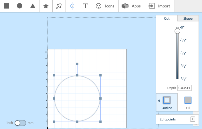
To run the “cut”, I pressed the Carve button. With the toggle buttons, I moved the machine on the X and Y axes by 0.1in just to make sure that my computer was properly communicating with the machine. I always made sure to return the carriage back to the origin. Much of the final settings have to do with securing the material and the spindle, so I just pressed continue for most of the steps until I could “carve”!
Video of the circle:
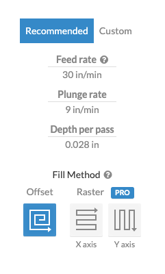
As you can probably hear in the video, we were confused as to why it moved so slowly. I made the carriage travel faster by changing the Cut Settings. The recommended cut settings has it traveling at 30 rpm, but I raised that to 100 rpm.
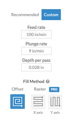
I ran the circle again, this time at 100rpm:
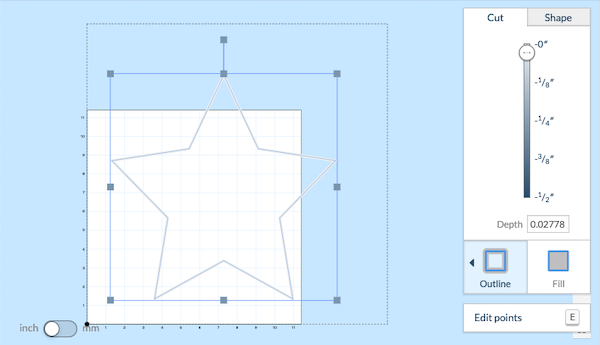
We thought that a star would be cool for a long exposure picture, so I created a star in the workspace. I adjusted the size as we ran it to make sure that the star outline was really defined.
Video of the star with the neopixel on:
Long exposure done with an iPhone app, courtesy of Will:

Will was having trouble with the light settings of the long exposure picture since the Neopixels are so bright. However, you can see the shape of the star in the glare! When we did it originally with Kai’s camera, he was able to get some really nice, clear shots. So, we are waiting to use Kai’s camera to take final photos.
With regard to the neopixel, Mr. Rudolph recommended that we plug it into the socket where the spindle should be plugged into. Then, when the spindle turns on, the light should come on as well. Currently, we just have the light always on.
Easel functions - Maxine
I messed around in Easel for a bit, and I found a bunch of cool stuff.
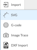
Import
I also discovered the import function, which could be really useful. I could design some design that’s more elaborate in Inkscape or Fusion 360 and then import them. Fusion allows the user to save any sketch as a .dxf, so the dxf and svg imports would probably be the most relevant and useful.
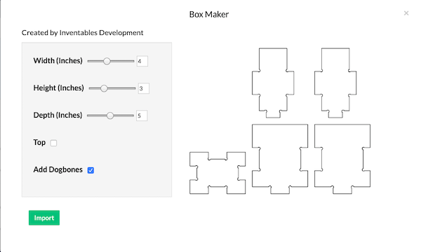
Box maker
Since Eagle is supposed to be used for cutting things, it even has a box maker! The user can change the width, length, depth, and whether it has a top. It even includes a dog bones, if desired. When finished with designing your box, you can simply click Import to put it into the design.
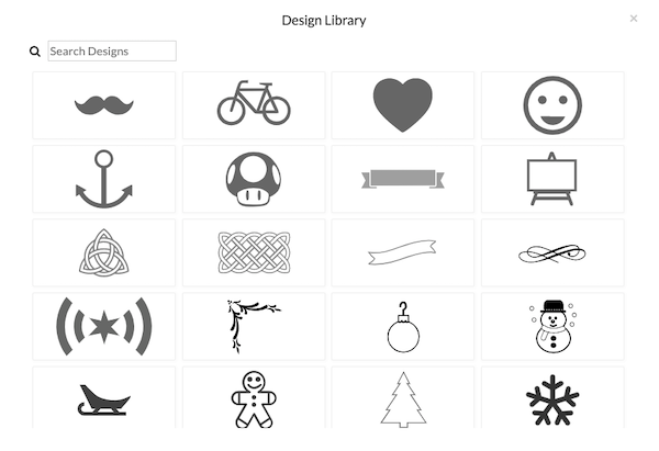
Design Library
Easel also includes a design library with a bunch of fun icons. These could actually be useful for our long exposure machine, especially since the outline function can produce an outline of any design very easily.
Exported G-code
I also saw that, if you don’t have the Grbl shield, Easel generates G-code. Underneath Machine and then Advanced Settings, you can download G-code that you can send over to a milling machine by pressing Generate g-code. Then, you Export g-code and it downloads it as a text file to your computer.
This is the G-code of the star that was shown in a video above:
G20
M3 S12000
G90
G1 Z0.15000 F9.0
G0 X10.26361 Y5.65955
G1 Z-0.02800 F9.0
G1 X13.24316 Y8.71335 F100.0
G1 X9.12552 Y9.34250 F100.0
G1 X7.28403 Y13.26572 F100.0
G1 X5.44257 Y9.34250 F100.0
G1 X1.32492 Y8.71335 F100.0
G1 X4.30447 Y5.65955 F100.0
G1 X3.60110 Y1.34747 F100.0
G1 X7.28403 Y3.38336 F100.0
G1 X10.96698 Y1.34747 F100.0
G1 X10.26361 Y5.65955 F100.0
G1 Z-0.04167 F9.0
G1 X13.24316 Y8.71335 F100.0
G1 X9.12552 Y9.34250 F100.0
G1 X7.28403 Y13.26572 F100.0
G1 X5.44257 Y9.34250 F100.0
G1 X1.32492 Y8.71335 F100.0
G1 X4.30447 Y5.65955 F100.0
G1 X3.60110 Y1.34747 F100.0
G1 X7.28403 Y3.38336 F100.0
G1 X10.96698 Y1.34747 F100.0
G1 X10.26361 Y5.65955 F100.0
G20
G90
G1 Z0.15000 F9.0
G0 X0.00000 Y0.00000
G4 P0.1
M5
Easel Functionality - Maxine
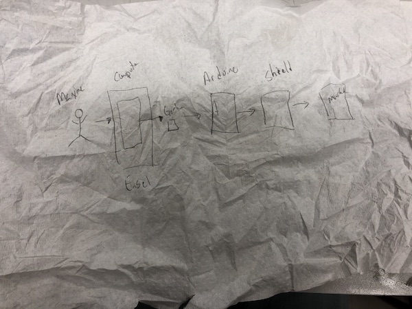
Dr. Fagan and Dr. Taylor helped me understand what Easel actually does. It uses the Grbl library within Arduino (which we loaded onto the “Arduino” that will made when he burned the bootloader). Then,Easel sends the G-code from the Grbl library to the Arduino. The shield has the drivers and is connected to the stepper motors, which move the axes we have via belts.
Dr. Fagan drew this picture illustrating the process I described above.
Future iterations
In future iterations, Mr. Rudolph suggested that we could hook up the neopixel to the area of the Grbl shield designated for the spindle. When the “spindle” is should turn on, the light will turn on. That would enable us to do do designs that have the light turn on and off (currently, the light is always on).
Video
Here is our video presenting our project!
https://drive.google.com/file/d/1WeSSRa7UDqj1qZWGTKF1rrMqosinkot7/view?usp=sharing
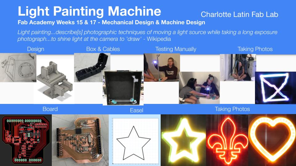
Slide
Here is our slide!