8. Computer controlled machining
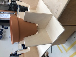
This week, I used the CNC machine to “make something big.” I choose to make connected plant pot holders. (It eventually turned out to be a coffee table.)
Designing
References
I researched a few plant bot designs for inspiration for my own design. I decided to combine the second and fourth references for my holder.
Sketches
Here are some sketches that Mr. Rudolf helped me develop.
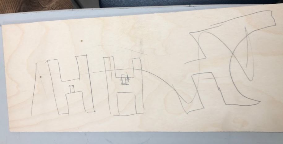
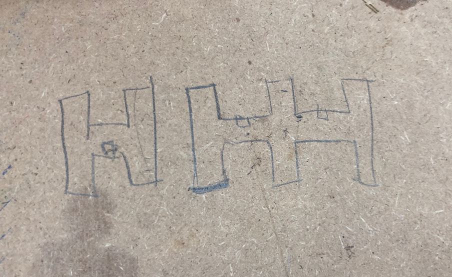
These are my own sketches! In the end, I diverged from my sketches a bit to adapt to the pots my mom found for me, but the general concept stayed the same.
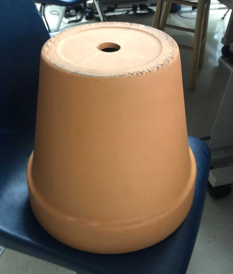
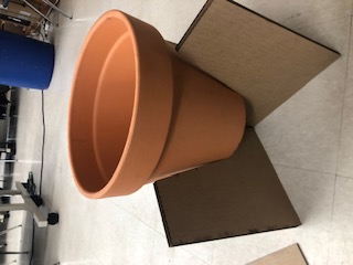
Originally, I was going to work with these pots, but I switched to this more measurable clay pot that I got from my neighbor.
Original Pots:
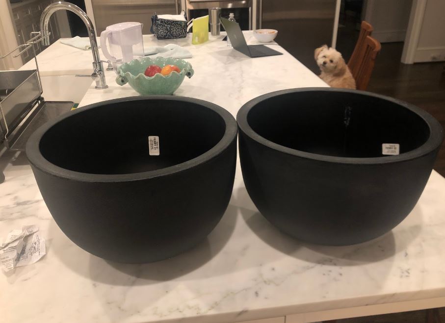
Neighbor’s Pot:
Lasercutting
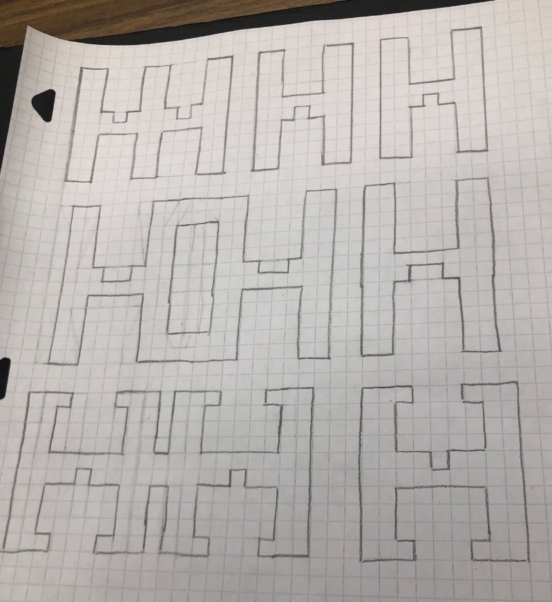
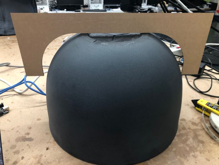
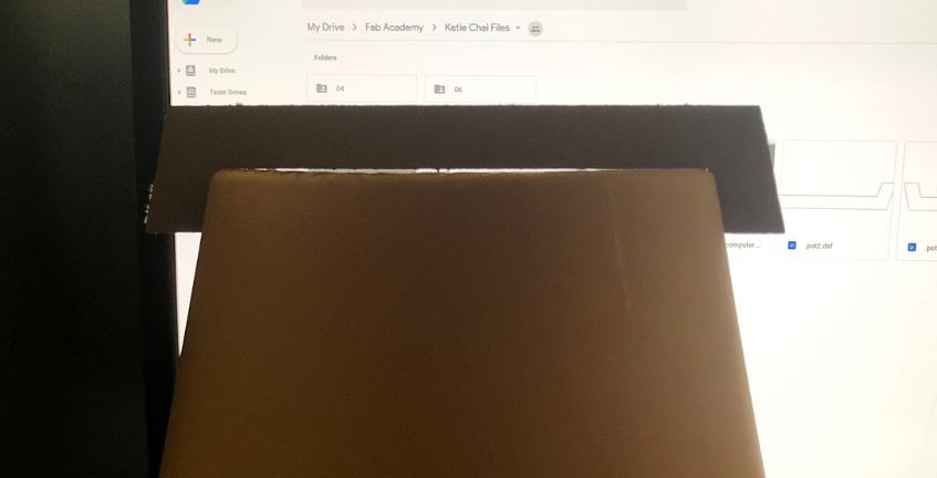
I lasercut a few prototypes for my plant holder before moving onto the CNC Machine.
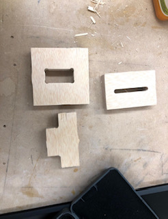
First Prototype: Too loose
Second Prototype: Too loose - 7.75 in, 75° angle (I switched pots so that I could get a tighter fit)

Third Prototype: Just right!
Fourth Prototype:
General Setup
Parameters
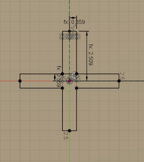
I designed my holder in two parts, but I created a few parameters that would help to dimension both parts.
Here are my parameters.
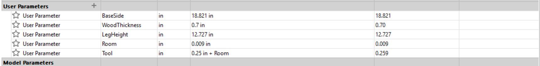
For some of my parameters, I added a clearance of 0.009 inches so that my wood would slip in more easily.
Before designing my holders, I also watched this video on stool making to understand flat pack furniture.
I decided to alter my design so it could be a plant holder from the top, but it could also serve as a coffee table if flipped upside down. (I did this as a backup plan in case my plant holder dimensions were incorrect.)
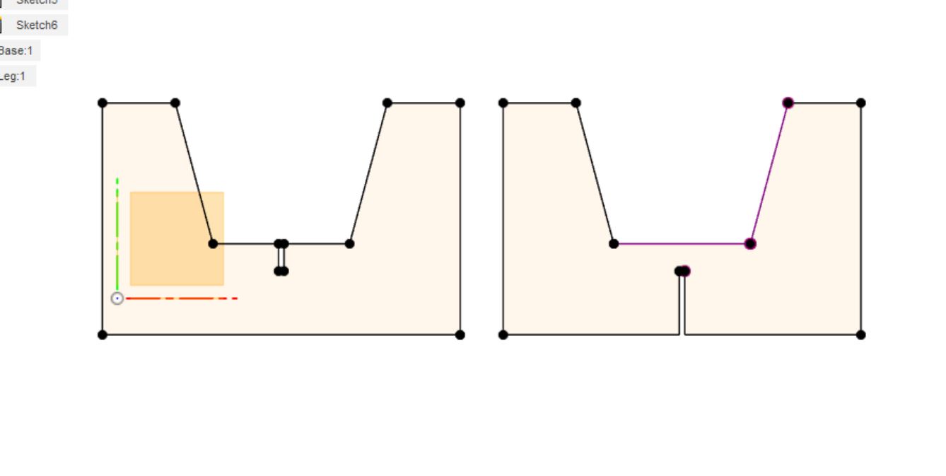
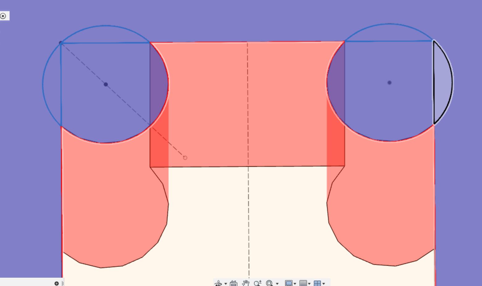
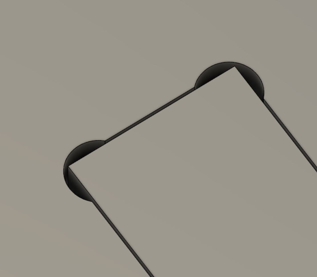
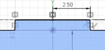
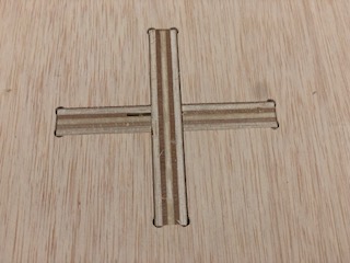
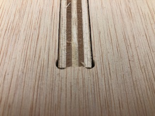
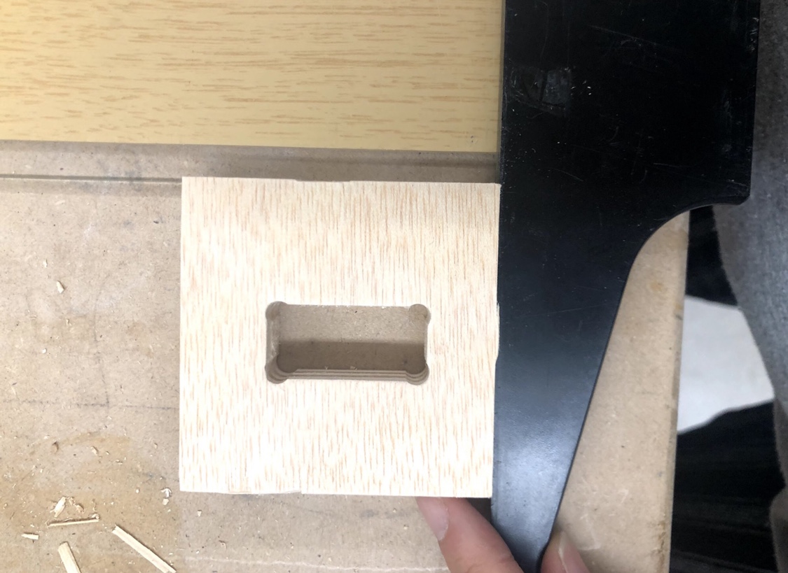
Dogbone Fillets
Throughout my design, I used dogbone geometry to assist in the creation of these slotting joints.
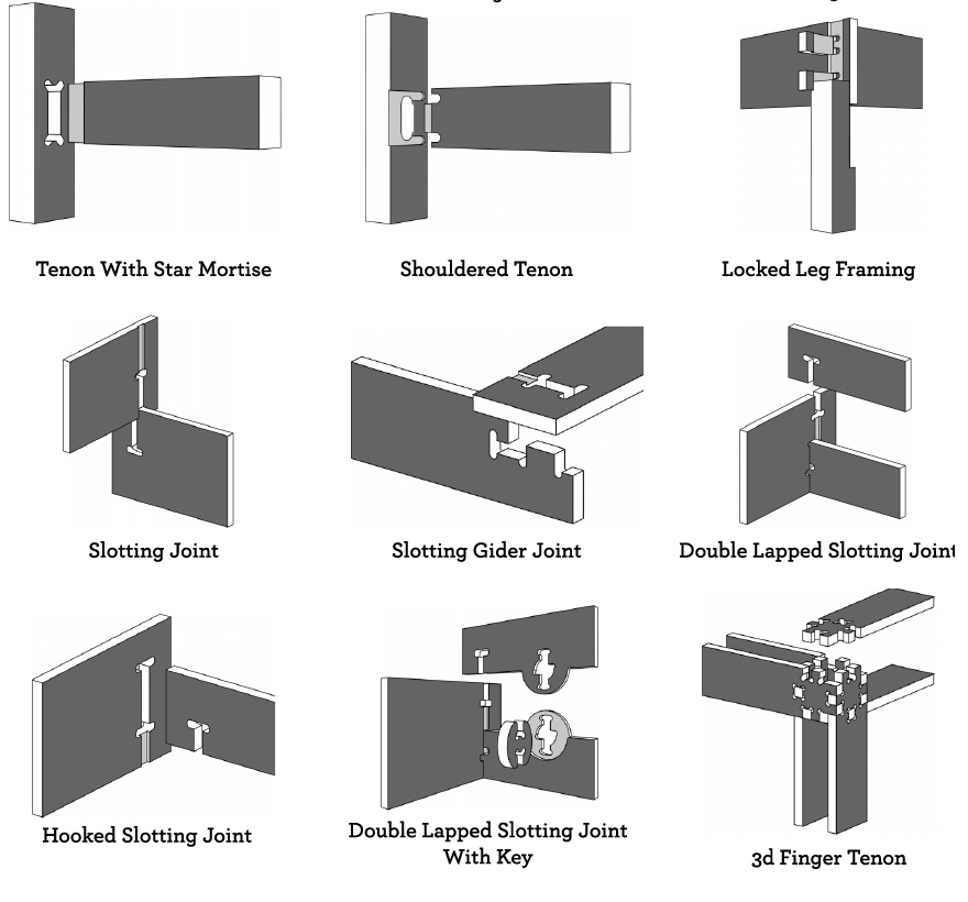
The dogbones would help the bit mill inside 90 degree corners.

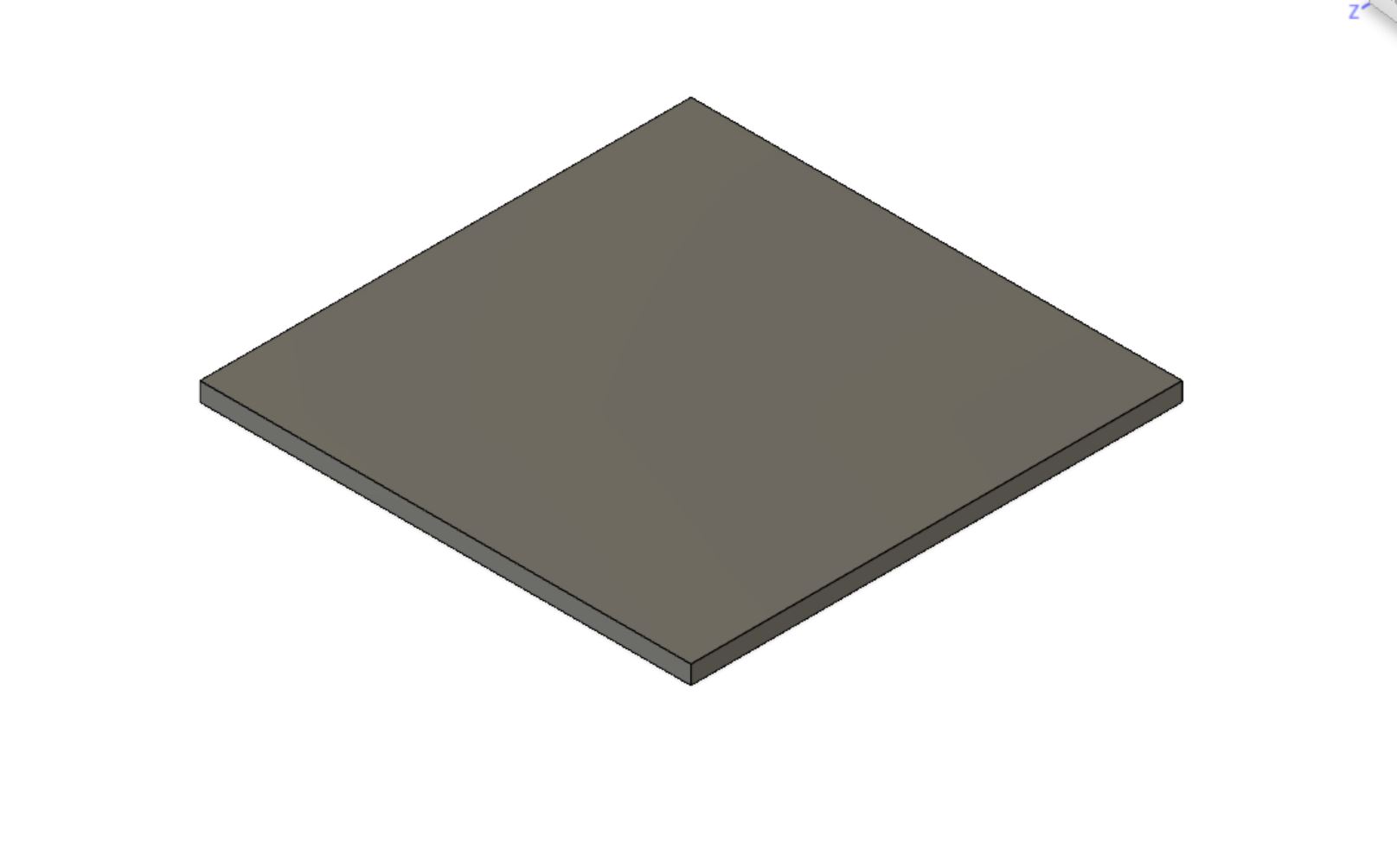
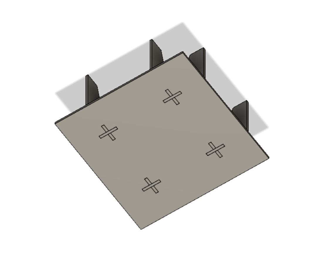
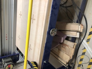
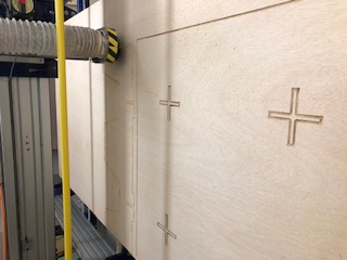
Base
The first part I designed was the base plate. The base mainly consisted of a square with the dimensions 18.821 inches x 18.821 inches. In the middle of the square, I put slot holes for the legs with dogbone fillets.
Legs
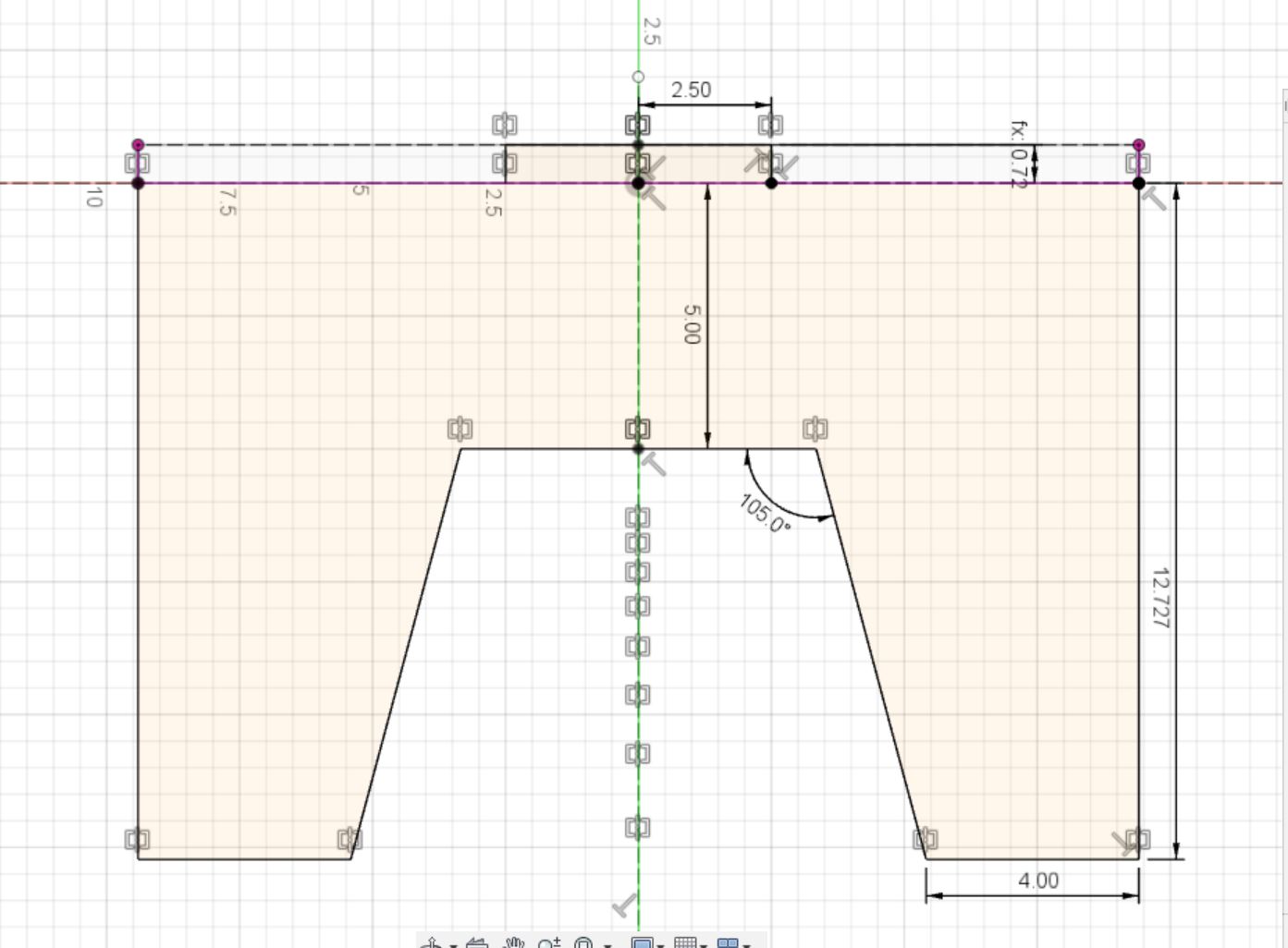
After constructing the base plate, I created a new plane for the legs. I recreated my lasercut leg design for my final legs.
Here is my lasercut leg design with the relevant dimensions.
I had to design a few tabs and slot so that the three pieces would fit together without glue.
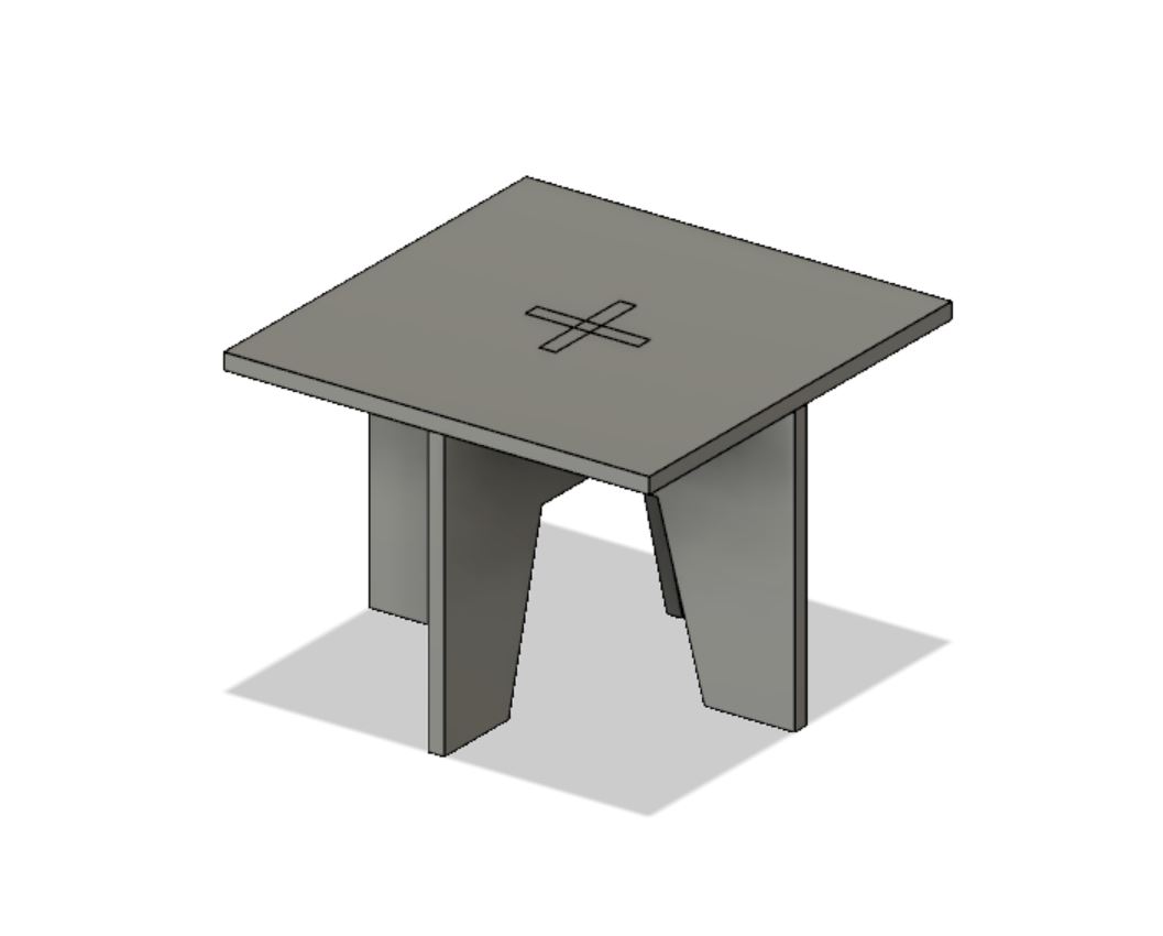
Once I had my legs and base designed, I duplicated and combined the bodies.
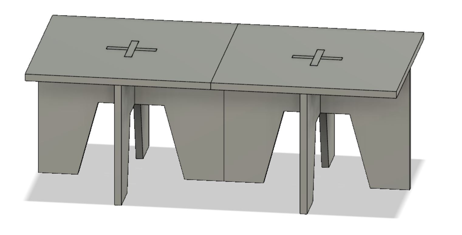
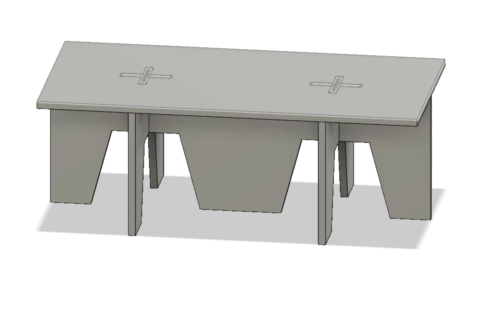
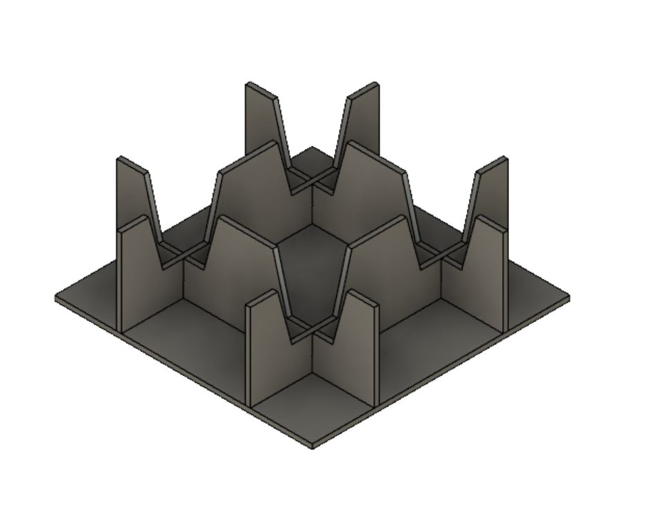
This is my final design.
Aspire
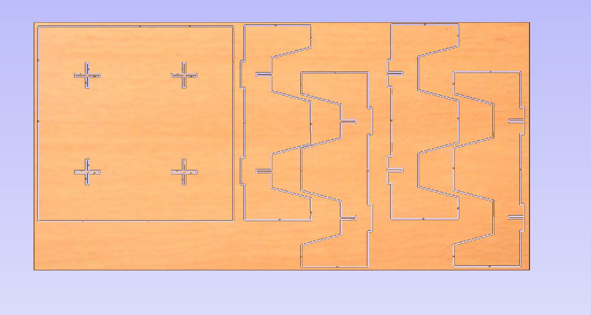
To convert my fusion file to a file compatible with our CNC machine, I used Shaper, Corel Draw, and Aspire softwares.
I started by converting all the faces of my design to SVGs using the Shaper software. After, I used Corel Draw to lay out my faces in a document with a length of 48 inches and a width of 96 inches.
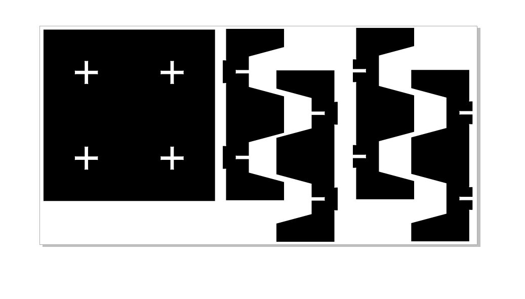
I opened the Corel Draw SVG in Aspire with the same length and width but with a thickness of 0.75 inches.
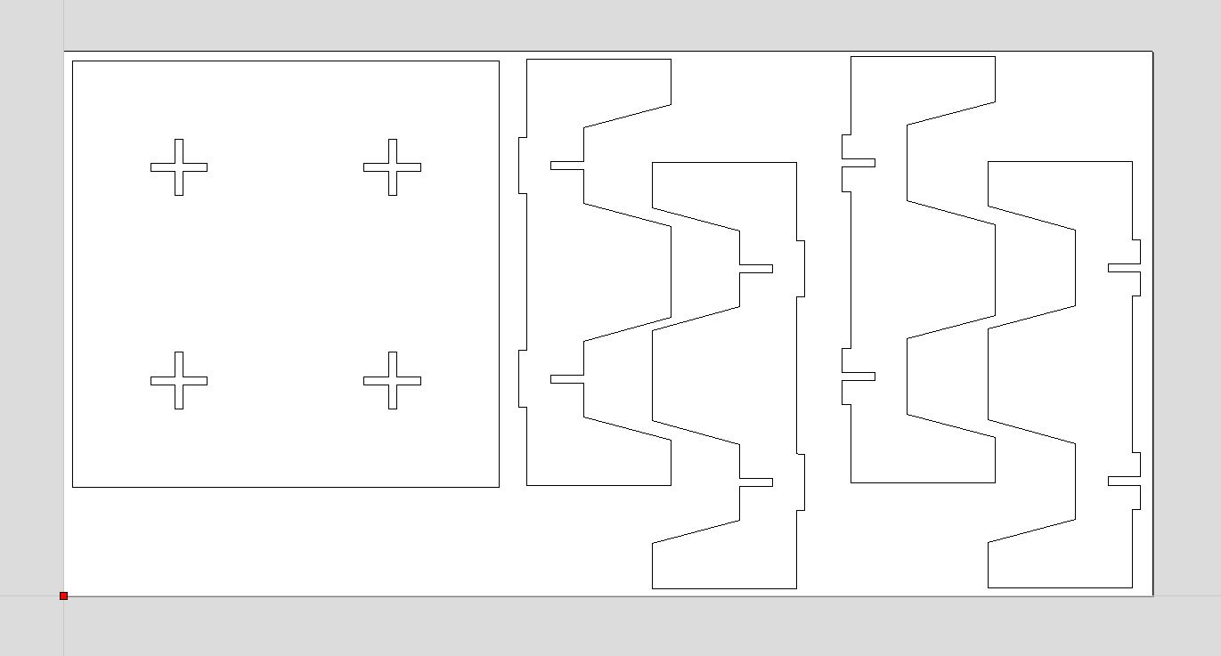
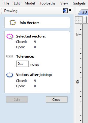
After my faces were laid out, I checked to see if my vectors were closed to make sure my cut would run as efficiently and quickly as possible.
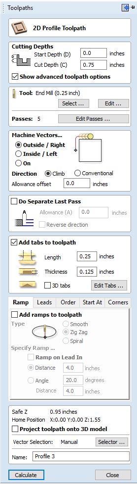
I created the tool path once my file was ready. I set my start depth to 0 and cut depth to 0.75 inches. I changed my tool to a 0.25 inch bit. Finally, I edited my number of passes to 3 and my speeds and feeds to 12000 (RPM) and 150 (feed rate).
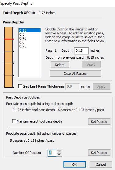
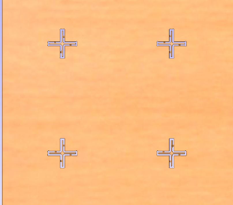
This is an example photo of the passes set to 5.
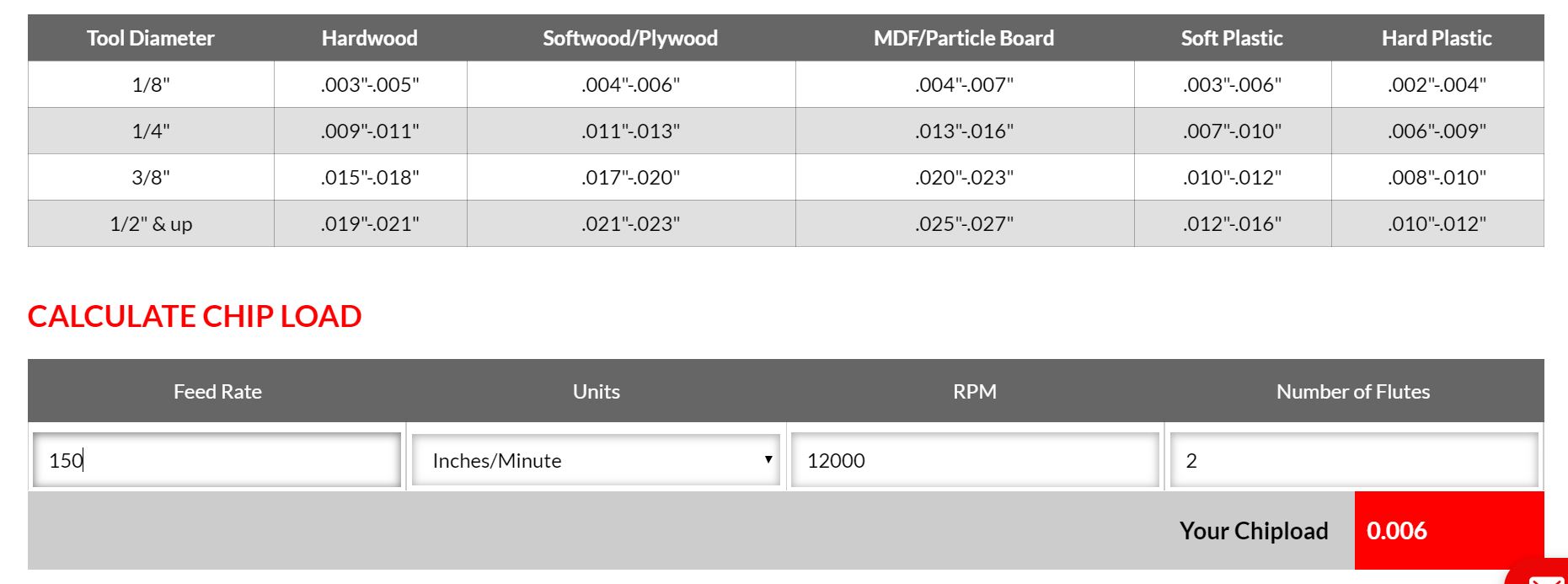
To find this I used this chipload calculator. Since I was using a 0.25 inch tool bit and plywood, I tried to keep my chipload around .004 inches to .006 inches.
I also made this chipload calculator in repl.it.
Once my chipload was calculated, I added some tabs (with sa length of 0.25 inches and a thickness of 0.125 inches) to my toolpath.
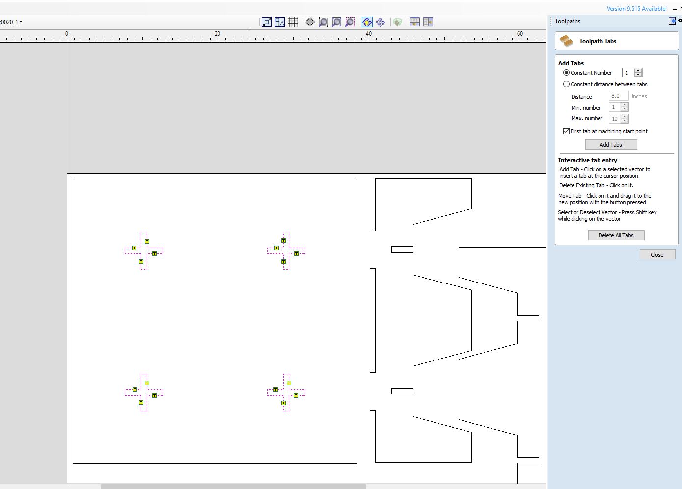
For my outline path, I used an outside cut, but for the slots inside my base plate, I used an inside cut.
Finally, I previewed my toolpaths to check the estimated times.
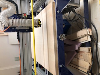
CNC Cutting
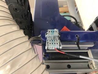
To cut my file, I used the standard ShopBot PRSalpha.
This is my CNC Workflow.
Shopbot Machine
-
Put on eye and ear protection
-
Close the doors
-
Check to see that the machine has been warmed up
-
Check to see bit is not loose
-
Measure thickness of material that you plan to cut.
-
Attach material to the table using screws
-
Raise Z AXIS 6 inches using the MZ 6 command
-
Use the proximity switch to set Calibrate. (C3 keyboard command)
-
Calibrate Z AXIS on the table. (C2 keyboard command)
-
Raise Z AXIS 6 inches using the MZ 6 command
-
Set new X and Y Origins for your design
-
Raise the Z-axis so the bit won’t drag on the table
-
Using keyboard move to the appropriate X and Y location. (M2 X,Y)
-
Using keyboard to zero the appropriate X and Y Location. (Z2)
-
You set origin.
-
Select Cut
-
Start up Aspire and VCarve software
-
Open your file
-
Select objects you wish to cut
-
Select Toolpath
-
Pin Toolpath
-
Click on material setup
-
Check Z - zero is on the bed, NOT the board
-
Enter the thickness of the material
-
Model position material should be the same thickness of the material.
-
Click OK.
-
Go to TOOL PATH OPERATIONS
-
Select 2D Profile Toolpath
-
Under cutting depth, select the cut depth of the material (CLS tools)
-
Select the proper tool -CLS down bit ¼
-
Click add tabs and add tabs
-
Hit CALCULATE
-
Preview toolpath
-
Click on CLOSE
-
Select SAVE TOOL PATH and save the file in a shopbot format
-
Start ShopBot Command Console
-
Conduct air cut
-
Select FILE-LOAD
-
Load the appropriate file
-
Select 1 3-D offset
-
Press ENTER
-
Turn on the spindle by pressing the big GREEN Button
-
You should hear a “SOUND” of the spindle now turning
-
Press ok
-
After checking that everything is good; press space bar
-
Select quit
-
Return to origin (M2 0,0)
-
Perform cut
-
Select FILE-LOAD
-
Load the appropriate file
-
Select no offset rather than 1 3-D offset
-
Press enter
-
Turn on the spindle by pressing the GREEN Button
-
You should hear a “SOUND”
-
Turn on the vacuum
-
Press enter again to start cut
-
Cut is done
-
Turn off vacuum (which is so loud you shouldn’t forget)
-
Clean up after yourself
Here are some common calibrating commands that I used when using the machine.
Calibrating Command:
-
C1: Change tool
-
C3: Home X and Y axis
-
C2: Calibrate Z
-
JZ: Z axis (raise to 6 so but won’t drag on table)
-
J2 X,Y: Jog X and Y
-
Z2: Set Origin (when designing software, stay near the origin so can change location in hardware)
-
Jog: Just move the machine (faster than Move)
-
Move: Moving the machine while cutting
To use the ShopBot, I had to follow the safety protocols.
Safety Protocols:
-
Partner Up
-
Hair up, ear protection, eye protection
-
Turn on projector display
-
Turn on fans
-
Know how to stop the machine (space bar or red button)
I also made sure to familurize myself with the following commands.
-
C1: Change tool
-
C3: Home X and Y axis
-
C2: Calibrate Z
-
JZ: Z axis (raise to 6 so but won’t drag on table)
-
J2 X,Y: Jog X and Y
-
Z2: Set Origin
Then, I had to calibrate the axis. I started with the z axis.
I calibrated the x and y axis with the proximity switches.
Once everything was calibrated correctly, I homed the machine.
Fixturing
To adhere my plywood onto the sacrificial CNC bed, I used screws.
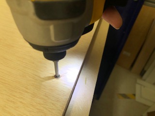
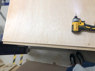
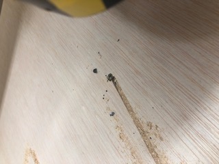
I made sure to place the crews in areas where I would not be cutting, but I miscalculated and accidentally placed one screw in the path of the tool. This cause the tool bit to break.
Here is a picture of the broken bit and screw.
Test Cut
Before officially running my ShopBot file, I ran a test cut. This helped to ensure that the tool bit would not hit any of the fixturing screws.
Actual Cut
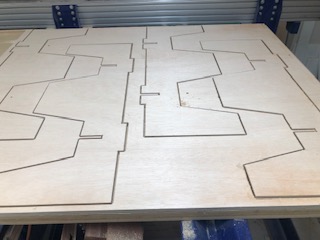
Base Cuts:
Leg Cuts:
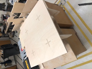
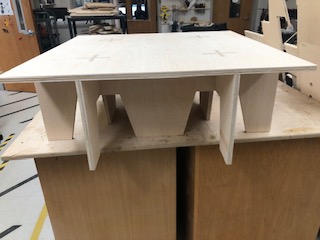
Assembling
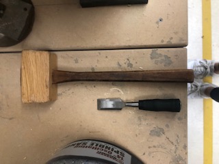
Before removing the fixture screws from the plywood, I chipped out the tabs using a chisel and a hammer.
This is what the tabs looked like before they were removed.
Here are my de-tabbing tools.
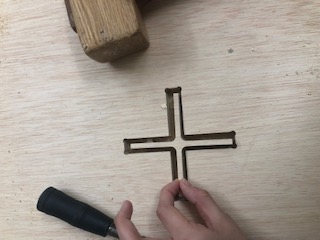
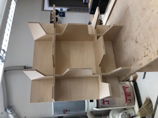
This is a de-tabbed chunk!
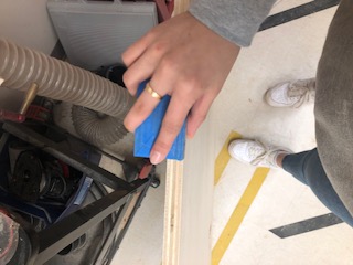
I sanded the edges of my pieces after removing them.
Finally, I used a hammer and another scrap piece of wood to insert the tabs into the slots.
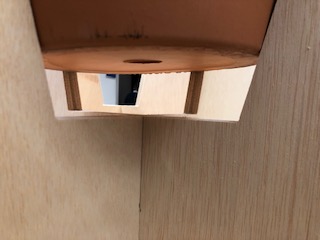
This is my final table/pot holder.
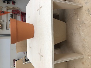
Sadly, my pot dimensions were not correct, probably because I did not account for the change in material thickness or kerf.
Group Assignment: Test runout, alignment, speeds, feeds, and toolpaths for your machine
Speed and Feeds - Deciding how deep to cut, how fast to turn the spindle, and how fast to move the tool
To begin learning about the CNC Machine, Mr. Rudolf walked us through the leveling process of the CNC Bed. This helped up familiarize ourselves with the commands.
This is a video of the lesson:
After leveling the table, we began to notice how the table was slightly uneven. This can be visually seen from the irregular grid lines (some are deep while some are shallow).
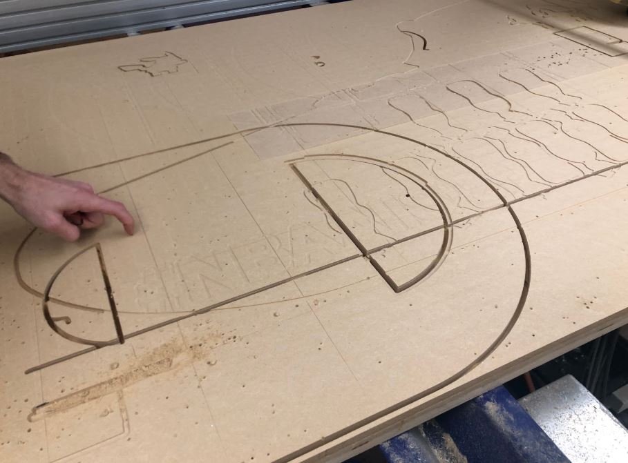
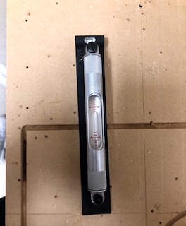
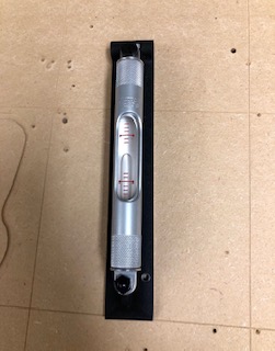
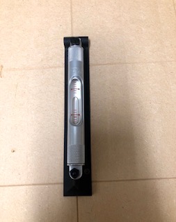
To further this hypothesis, we compared level measurements at different areas of the table.
Beginning:
Middle:
End:
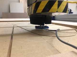
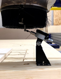
Then, we checked the runout of the bot using a Starrett Dial Indicator.
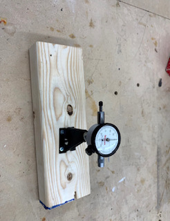
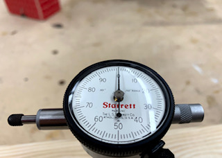
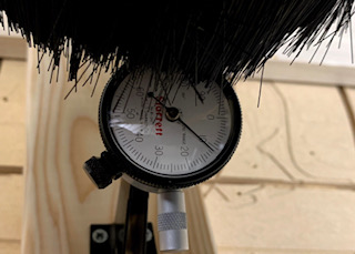
Unfortunatly, our runout test was slightly inaccurate because the dial indicator was installed at an angle. :(
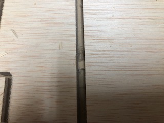
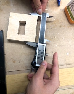
Finally, we checked the machine’s axis calibration and kerf by cutting out a 3 inch x 3 inch square, a tab and slot piece, and a 0.25 inch line.
We found that our machine was calibrated well enough that it would not seriously impact or designs. We came to a similar conclusion about the kerf.
90 degree angle:
3 inch side (almost):
Files
Here are my STL files: Download Files