12. Output devices
This week, I started working on powering an output device with my microcontroller board. I also want to look into varying the timing or brightness of the LED.
Board Development
For my board this week, I “stole” the board that I was initially planning on using for input week.
I choose to use this input board for this week because while it was not receiving input signals correctly, it was blinking the LED. (Since I used my input board, there is an added 4 pin header that I had planned to use to recieve signals attached to my board. I did not use this for the output device assignment.)
(I choose to create a new board for input week which would hopefully be reused for my final project.)
After looking through a few different sources, I found this Fab Academy Site which modeled a board after Professor Gershenfeld’s motion board. After seeing these 2 examples, I started creating my first board.
ATtiny45 Microcontroller Board
Since I switched from the ATtiny44 to the ATtiny45, I had to look at the ATtiny45 datasheet to find the pinout diagram.

This is the ATtiny45 datasheet that I refered when creating my board around the ATtiny 45 chip.
Attempt 1
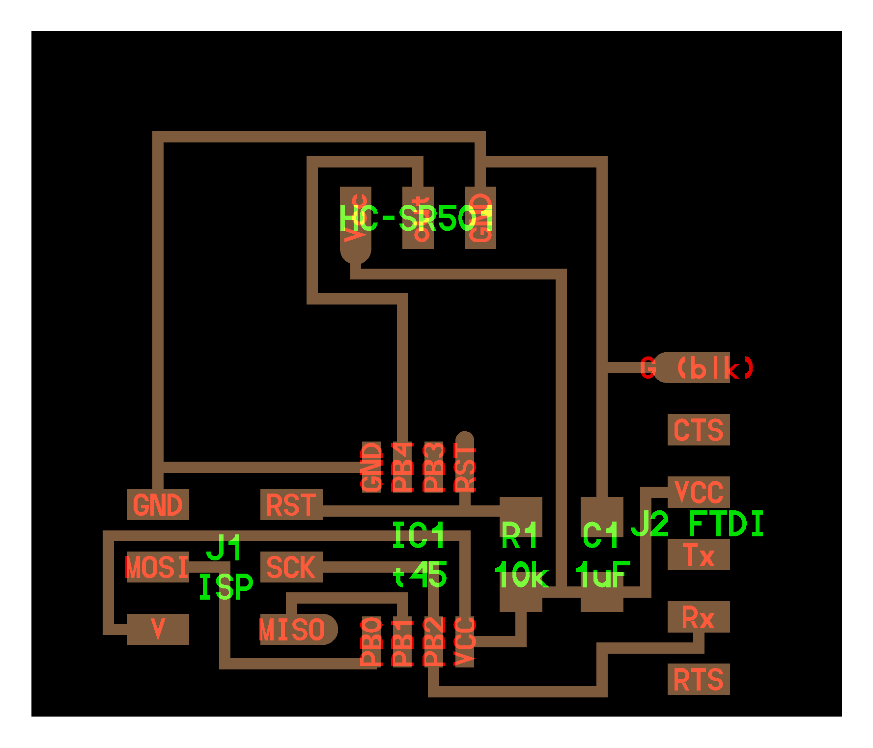
Here is my first schematic.

Here is my first board.

(I could not route two of the paths leading to the pin header. I decided to just solder a jumper wire between the two connections.)
After soldering my components onto my board, I found that it would not burn the bootloader. My first attempt at fixing the problem was remilling and resoldering my board to see if I had accidentally bridges anything with solder. (I had included through two hole pin headers in my design which I was having trouble soldering.)
I did this a few times before changing my trace clearance to help with soldering mistakes. This adjustment was helpful, but my board would still not work.
![]()
I decided to test my connections with a multimeter. I found that this design did not work for me.
Reasons for Failure:
- I choose a lot of through hole components that were difficult to solder. All of the boards that I solder seemed to be bridged, ripped, or melted.

- After checking some voltages with a multimeter, I found that my chip was not connected to the rest of the board at some point. (I’m not sure if my soldering job interfered with my readings.)
After assessing the situation, I decided to create a new board design. This design would have my LED and more surface mount components.
With this second attempt, I was having trouble routing the traces, but Dr. Harris gave me this helpful reference picture for my ATtiny routing.

After milling, soldering, and testing a few of these new boards, I found that my LED was constantly being powered…
I discussed the problem with Dr. Taylor who reccomended that I look back into my schmatic to see what was going wrong, so I decided to walk through this ATtiny tutorial in hopes of finding my error.
Attempt 2
After hooking up the ATtiny45 up to the Arduino, I figured out that I had not connected the ATtiny in my schematic to the ground on the pin header. Oops. I fixed the problem, reassembled the board, and was finally able to burn the bootloader.
Here is the schematic with the connection to ground:

Here is the board:

Programming
I tested the above design by burning the bootloader. Once I was able to burn the bootloader, I tried out this blink example from the Ardunio IDE. It worked!
Here is the code I used to blink my LED. (I changed the pin to 3 for my board.)
/*
  Blink

  Turns an LED on for one second, then off for one second, repeatedly.

  Most Arduinos have an on-board LED you can control. On the UNO, MEGA and ZERO
  it is attached to digital pin 13, on MKR1000 on pin 6. LED_BUILTIN is set to
  the correct LED pin independent of which board is used.
  If you want to know what pin the on-board LED is connected to on your Arduino
  model, check the Technical Specs of your board at:
  https://www.arduino.cc/en/Main/Products

  modified 8 May 2014
  by Scott Fitzgerald
  modified 2 Sep 2016
  by Arturo Guadalupi
  modified 8 Sep 2016
  by Colby Newman

  This example code is in the public domain.

  http://www.arduino.cc/en/Tutorial/Blink
*/

// the setup function runs once when you press reset or power the board
void setup() {
  // initialize digital pin LED_BUILTIN as an output.
  pinMode(3, OUTPUT);
}

// the loop function runs over and over again forever
void loop() {
  digitalWrite(3, HIGH);   // turn the LED on (HIGH is the voltage level)
  delay(1000);                       // wait for a second
  digitalWrite(3, LOW);    // turn the LED off by making the voltage LOW
  delay(1000);                       // wait for a second
}
This is a video of my LED blinking.
Group Assignment: Measure the power consumption of an output device
For our group project this week, we decided to mesure the power consumption of an LED.
Here is the video of our tests!
We used a multimeter to find the volts and amps needed to light the LED. We started with the voltage test (Setup and Readings 1). This test went pretty well. I felt like we were all pretty used to measuring the voltages when our boards were not working.
Voltage Consumption = 2.67
After we finished measuring the voltage, we measued the amps. This was more difficult. We found that we had to include the multimeter prongs in the circuit flow to get an actual reading. After we made this change, we were able to find our ampere consumption (Setup and Readings 2).
Ampere Consumption = 8.18
Files
Here are all my files from this week: Download Files