9. Embedded programming
This week, I was tasked with reading the 286 page ATtiny 44 datasheet and programming my board in as many languages a possible!
Datasheet
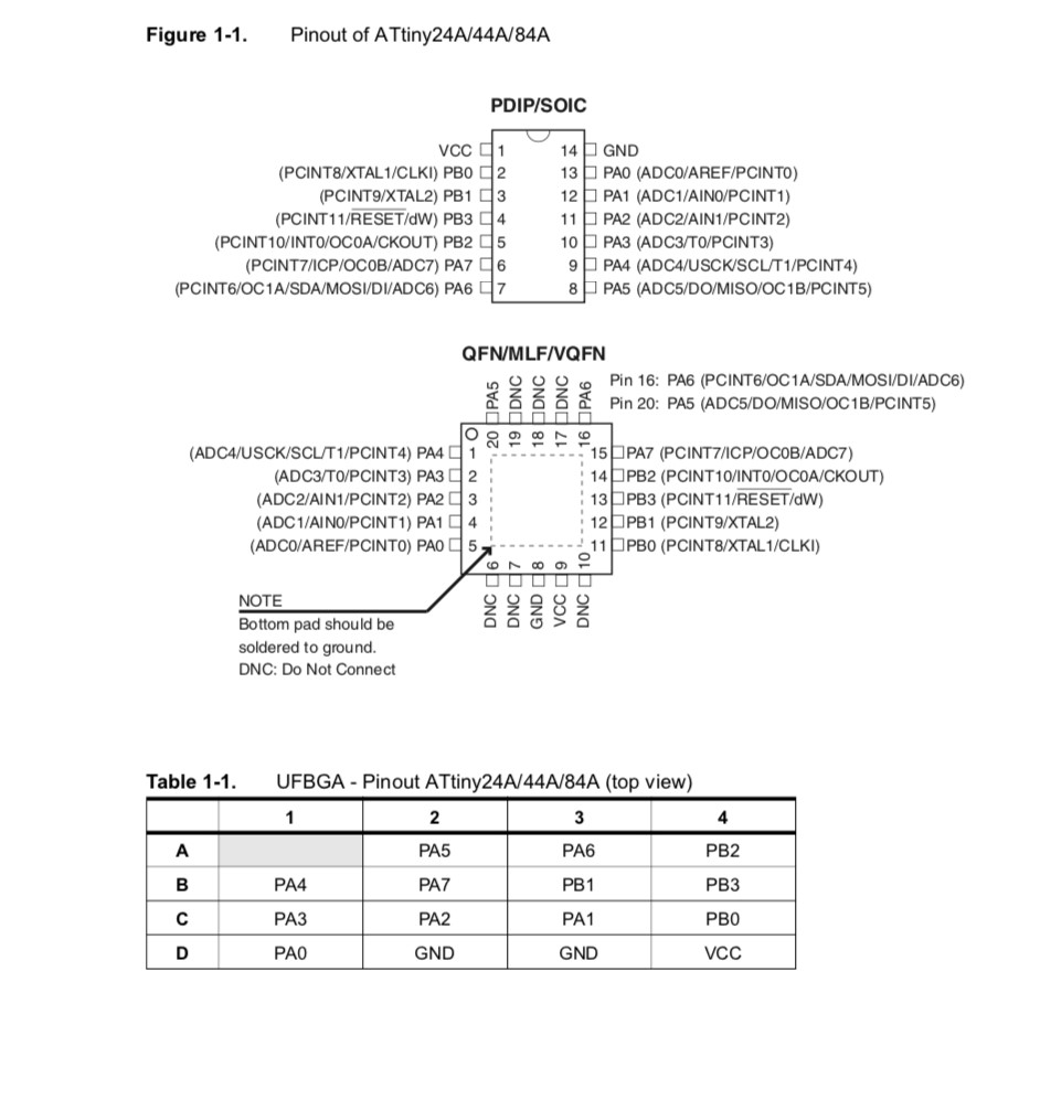
This is the ATtiny pinout diagram. I referenced this later when programmig with Arduino so I could use the correct analog pin for my LED.
AVR uses an AVR enhanced RISC architecture which looks like this. (The architecture ends up falling under the Harvard architecture catagory.)

For program memory, the AVR uses an In-System Reprogrammable Flash memory. This is a map of the program memory.

To clock/time the commands, the AVR uses the following system.

For a reset system, the AVR uses this logic.

The ATtiny chip operates on an universal serial interface which allows serial communication. Here is the USI Block diagram.

The chip uses an AC to DC Converter to convert from analog signals to digital signals. This is the converter schematic.

The chip hardware is incased in a small package with these dimensions.


Programming
Arduino
I started this week by programming my board with the Arduino IDE.
To find the pin numberings of the ATtiny 44, I referenced the pinout diagram from the datasheet.
I also set the board and programmer settings to the ATtiny 44 and USBtinyISP like when programming the echo program in week 7.

Here is the code for the 1 second delay.
/*
  Blink

  Turns an LED on for one second, then off for one second, repeatedly.

  Most Arduinos have an on-board LED you can control. On the UNO, MEGA and ZERO
  it is attached to digital pin 13, on MKR1000 on pin 6. LED_BUILTIN is set to
  the correct LED pin independent of which board is used.
  If you want to know what pin the on-board LED is connected to on your Arduino
  model, check the Technical Specs of your board at:
  https://www.arduino.cc/en/Main/Products

  modified 8 May 2014
  by Scott Fitzgerald
  modified 2 Sep 2016
  by Arturo Guadalupi
  modified 8 Sep 2016
  by Colby Newman

  This example code is in the public domain.

  http://www.arduino.cc/en/Tutorial/Blink
*/

// the setup function runs once when you press reset or power the board
void setup() {
  // initialize digital pin LED_BUILTIN as an output.
  pinMode(7, OUTPUT);
}

// the loop function runs over and over again forever
void loop() {
  digitalWrite(7, HIGH);   // turn the LED on (HIGH is the voltage level)
  delay(1000);                       // wait for a second
  digitalWrite(7, LOW);    // turn the LED off by making the voltage LOW
  delay(1000);                       // wait for a second
}
To change the delay, you edit the following line: (1000 = 1 second)
delay(1000); // wait for a second
Then, I added my button into the equation using this code. (I got it from the Arduino sample code, but I changed the ports to fit the ATtiny44.)
/*
  Button

  Turns on and off a light emitting diode(LED) connected to digital pin 13,
  when pressing a pushbutton attached to pin 2.

  The circuit:
  - LED attached from pin 13 to ground
  - pushbutton attached to pin 2 from +5V
  - 10K resistor attached to pin 2 from ground

  - Note: on most Arduinos there is already an LED on the board
    attached to pin 13.

  created 2005
  by DojoDave <http://www.0j0.org>
  modified 30 Aug 2011
  by Tom Igoe

  This example code is in the public domain.

  http://www.arduino.cc/en/Tutorial/Button
*/

// constants won't change. They're used here to set pin numbers:
const int buttonPin = 3;     // the number of the pushbutton pin
const int ledPin =  7;      // the number of the LED pin

// variables will change:
int buttonState = 0;         // variable for reading the pushbutton status

void setup() {
  // initialize the LED pin as an output:
  pinMode(ledPin, OUTPUT);
  // initialize the pushbutton pin as an input:
  pinMode(buttonPin, INPUT);
}

void loop() {
  // read the state of the pushbutton value:
  buttonState = digitalRead(buttonPin);

  // check if the pushbutton is pressed. If it is, the buttonState is HIGH:
  if (buttonState == HIGH) {
    // turn LED on:
    digitalWrite(ledPin, HIGH);
  } else {
    // turn LED off:
    digitalWrite(ledPin, LOW);
  }
}
For some reason my button was not working as expected. The LED would turn off when the buttom was clicked. I remember Will having the same problem, so I looked on his site to see how he solved it. I found out that you had to specify direction, ports, and pins.
TinkerCircuit
After I had finished with this Arduino code, I back tracked to a program called TinkerCircuit. This program used block based code whereas the Arduino IDE used text based code.
Here is a comparison between the TinkerCircuit block based code and the Arduino IDE text based code.

Atmel Studio
Then, I looked into Atmel Studio which I learned is a program that allows for AVR code development and debugging. The languages offered are: C/C++, and assembly code.
Once in Atmel Studio, I created a new project.

I selected the ATtiny 44 as my device.

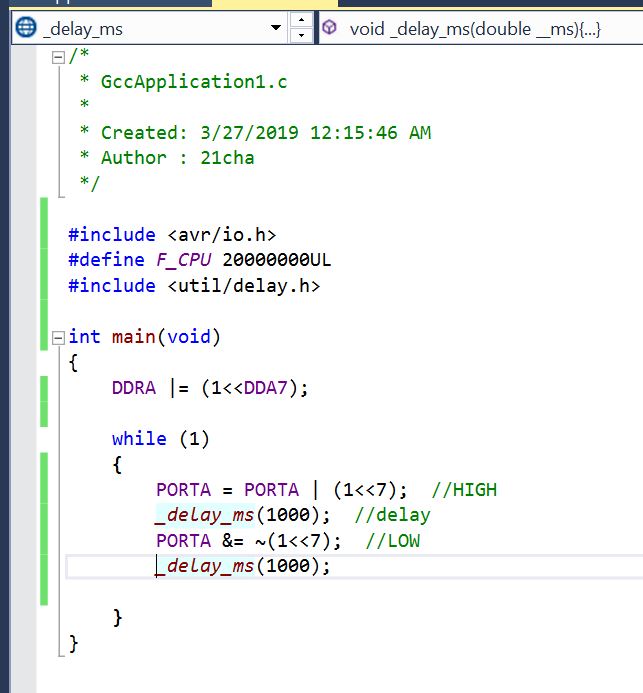
Here is the code that I tried to run. I learned how to write this code by watching this video that demonstrated a similar concept but for a ATtiny85. I found that as long as I wrote my code according to the ATtiny 44 datasheet instead of the ATtiny85 datasheet that he was referencing, the code was basically the same.
/*
 * GccApplication1.c
 *
 * Created: 3/27/2019 12:15:46 AM
 * Author : 21cha
 */

#define F_CPU 20000000UL  // clock speed
#include <avr/io.h>  // library
#include <util/delay.h>

int main(void)
{
    DDRA |= (1<<7);  // OUTPUT

    while (1)
    {
        PORTA = PORTA | (1<<7);  //HIGH
        _delay_ms(1000);  //delay
        PORTA &= ~(1<<7);  //LOW
        _delay_ms(1000);

    }
}
Once I had the code written, I attempted to use the debug feature, but I recieved this error message.

I tried to program the chip, but I could not find my programmer.

I was getting very confused at this point, so I met with Dr. Harris to see if any of my code was wrong.(I presumed my hardware was still working since my LED blinked with the Arduino code.)
After talking to Dr. Harris, I found my code was seemingly correct! He tried to help me navigate Atmel Studio, but in the end we decided to try using the code that I had developed in a different platform.
Here is a picture of the Atmel hex file in the Atmel folder of my computer.

Command
Here is the Makefile that Professor Gershenfeld created. I used this line of the Makefile that I “stole” for my own “Makefile”. I changed the name of his hex file to the name of my hext file.


Here is my command transcript.
Microsoft Windows [Version 10.0.17134.648]
(c) 2018 Microsoft Corporation. All rights reserved.

C:\Users\21cha>cd C:\Users\21cha\Documents\Atmel Studio\7.0\GccApplication1\GccApplication1\Debug

C:\Users\21cha\Documents\Atmel Studio\7.0\GccApplication1\GccApplication1\Debug>dir
 Volume in drive C is Local Disk
 Volume Serial Number is 8869-B254

 Directory of C:\Users\21cha\Documents\Atmel Studio\7.0\GccApplication1\GccApplication1\Debug

03/27/2019  06:15 PM    <DIR>          .
03/27/2019  06:15 PM    <DIR>          ..
03/27/2019  06:15 PM                13 GccApplication1.eep
03/27/2019  06:15 PM             6,952 GccApplication1.elf
03/27/2019  06:15 PM               304 GccApplication1.hex
03/27/2019  06:15 PM             4,396 GccApplication1.lss
03/27/2019  06:15 PM            13,914 GccApplication1.map
03/27/2019  06:15 PM               348 GccApplication1.srec
03/27/2019  06:15 PM             3,152 main.d
03/27/2019  06:15 PM             3,924 main.o
03/27/2019  12:20 AM               240 makedep.mk
03/27/2019  06:15 PM             4,020 Makefile
              10 File(s)         37,263 bytes
               2 Dir(s)  422,044,471,296 bytes free

C:\Users\21cha\Documents\Atmel Studio\7.0\GccApplication1\GccApplication1\Debug>avrdude -p t44 -P usb -c usbtiny -U flash:w:GccApplication1.hex

avrdude: AVR device initialized and ready to accept instructions

Reading | ################################################## | 100% 0.05s

avrdude: Device signature = 0x1e9207
avrdude: NOTE: FLASH memory has been specified, an erase cycle will be performed
         To disable this feature, specify the -D option.
avrdude: erasing chip
avrdude: reading input file "GccApplication1.hex"
avrdude: input file GccApplication1.hex auto detected as Intel Hex
avrdude: writing flash (100 bytes):

Writing | ################################################## | 100% 0.13s


avrdude: 100 bytes of flash written
avrdude: verifying flash memory against GccApplication1.hex:
avrdude: load data flash data from input file GccApplication1.hex:
avrdude: input file GccApplication1.hex auto detected as Intel Hex
avrdude: input file GccApplication1.hex contains 100 bytes
avrdude: reading on-chip flash data:

Reading | ################################################## | 100% 0.10s


avrdude: verifying ...
avrdude: 100 bytes of flash verified

avrdude: safemode: Fuses OK

avrdude done.  Thank you.


C:\Users\21cha\Documents\Atmel Studio\7.0\GccApplication1\GccApplication1\Debug>avrdude -p t44 -P usb -c usbtiny -U flash:w:GccApplication1.hex
This is a video of my LED blinking with the Atmel file and the commandline!
Force Sensor
I decided to work with a force sensor to work towards my final project. At first, I debated between using a force sensor or a flex sensor. I found sample projects for both sensors, but I decided on using the force sensor because I wanted to measure both force and depth accuratly and I thought this could be more efficiently done with a force sensitive resistor.
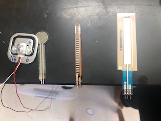
Tutorial for Force Sensitive Resistor (I ended up following the Adafruit tutorial for this week)
For my connections, I used GND, 5V, and analog pin 0. I hope to apply this knowledge to my final board design.
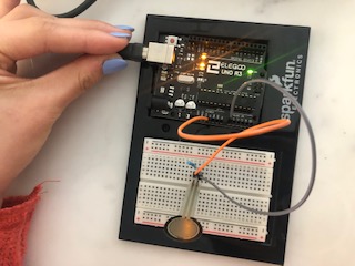
Here is the code I ran for my test.
/* FSR simple testing sketch.
Connect one end of FSR to power, the other end to Analog 0.
Then connect one end of a 10K resistor from Analog 0 to ground
For more information see www.ladyada.net/learn/sensors/fsr.html */
int fsrPin = 0; // the FSR and 10K pulldown are connected to a0
int fsrReading; // the analog reading from the FSR resistor divider
void setup(void) {
// We'll send debugging information via the Serial monitor
Serial.begin(9600);
}
void loop(void) {
fsrReading = analogRead(fsrPin);
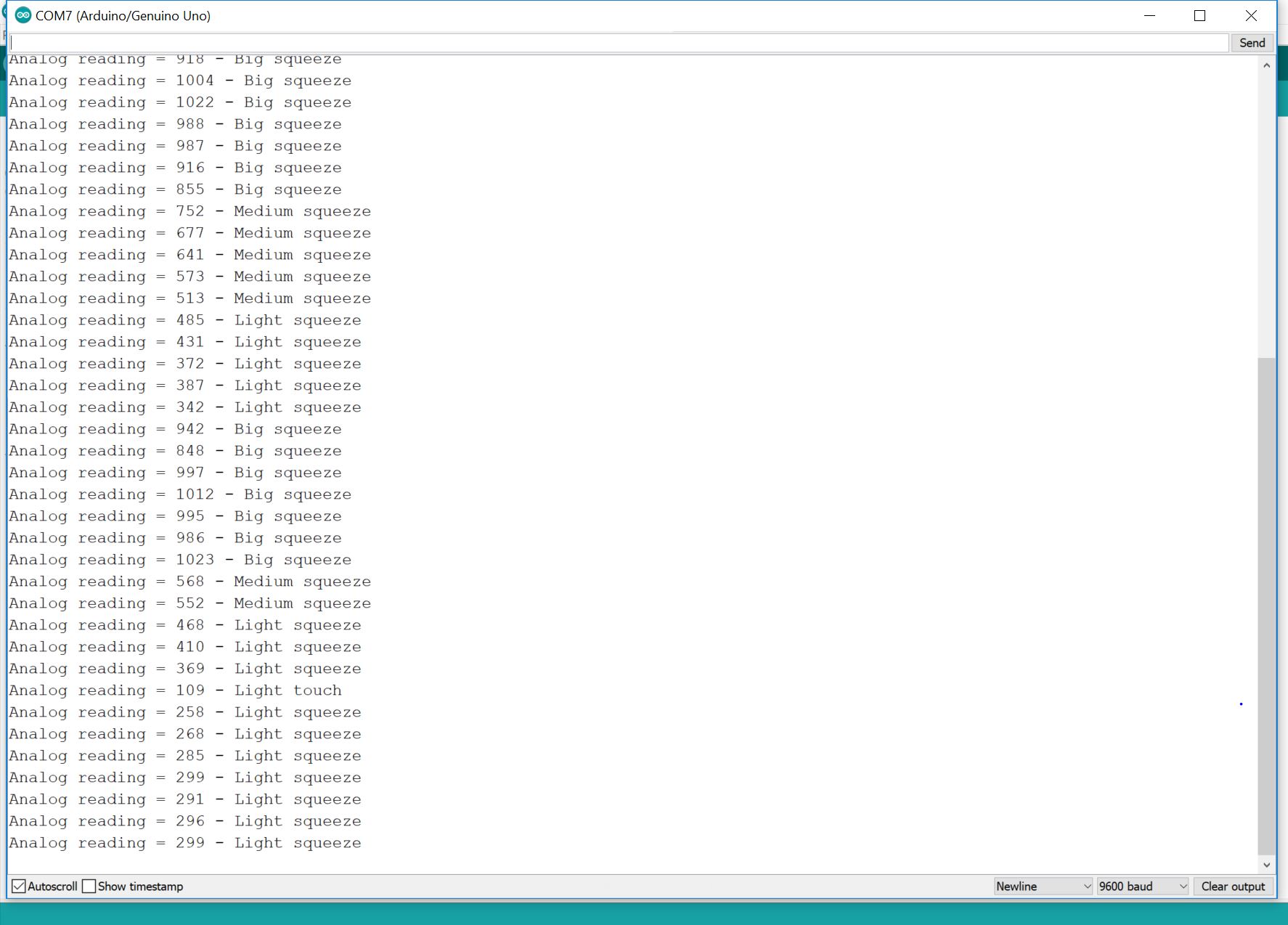
Serial.print("Analog reading = ");
Serial.print(fsrReading); // the raw analog reading
// We'll have a few threshholds, qualitatively determined
if (fsrReading < 10) {
Serial.println(" - No pressure");
} else if (fsrReading < 200) {
Serial.println(" - Light touch");
} else if (fsrReading < 500) {
Serial.println(" - Light squeeze");
} else if (fsrReading < 800) {
Serial.println(" - Medium squeeze");
} else {
Serial.println(" - Big squeeze");
}
delay(1000);
}
Here’s a video of my test.
Here is a photo of the serial monitor readings.
Group Assignment: Compare the performance and development workflows for other architectures
RaspberryPi
For our group assignment, we started with a RaspberryPi 3 Model 3B connected to the internet using an onboard Wifi antenna. The RaspberryPI we used had OS and Raspbian Jessie Lite already installed thanks to Kai.
This is a video on the RaspberryPi 3B website that explains the general concept of a RaspberryPi.
I also found these specs for our specific model. Considering the size of the computer, the ammount of “stuff” packed into the board is pretty impressive.
-
Quad Core 1.2GHz Broadcom BCM2837 64bit CPU
-
1GB RAM
-
BCM43438 wireless LAN and Bluetooth Low Energy (BLE) on board
-
100 Base Ethernet
-
40-pin extended GPIO
-
4 USB 2 ports
-
4 Pole stereo output and composite video port
-
Full size HDMI
-
CSI camera port for connecting a Raspberry Pi camera
-
DSI display port for connecting a Raspberry Pi touchscreen display
-
Micro SD port for loading your operating system and storing data
-
Upgraded switched Micro USB power source up to 2.5A
Here are some external materials that RaspberryPi reccomended to get started.
-
Micro SD card with NOOBS
-
Micro USB power supply (2.1 A)
-
TV or monitor and HDMI cable
-
Keyboard and mouse
This is the raspberrypi hooked up to a computer, our classroom projector, and a keyboard using some of the materials listed above.

To create our code document, we typed sudo nano test_code.py. I had previously been using only the nano command, but according to Kai, sudo gives you administrator privileges and allows for more secure communication.

We started by writing a print command which is *print(“Hello”)

Once we were happy with our code, we saved the document by pressing command x and then y.

We went back to the main screen and ran our test code document using the python test_code.py command.

This is our printed message.

To see every line of code that has been written, we found we could use the sudo transcript.log and nano transcript .log commands.
![]()
This is the code we used to blink the LED. (This is a tutorial that explains the lines in detail.)

from time import sleep # Import the sleep function from the time module

GPIO.setwarnings(False) # Ignore warning for now
GPIO.setmode(GPIO.BOARD) # Use physical pin numbering
GPIO.setup(8, GPIO.OUT, initial=GPIO.LOW) # Set pin 8 to be an output pin and set initial value to low (off)

while True: # Run forever
 GPIO.output(8, GPIO.HIGH) # Turn on
 sleep(1) # Sleep for 1 second
 GPIO.output(8, GPIO.LOW) # Turn off
 sleep(1) # Sleep for 1 second
This is our blinking LED!
PocketChip
After looking at this architecture, we also explored the PocketChip. PocketChip has actually gone out of business, so to access their website, we used this link which shows the last cache of an older website.

The PocketChip has many capabilities, but we focused on the Terminal application. Once in terminal, we opened a python document using the command, nano blink.py.

This is the code we ran to blink the LED found from this website.
import CHIP_IO.GPIO as GPIO
import time

GPIO.cleanup()
GPIO.setup("XIO-P2", GPIO.OUT)
print "Toggling XIO-P1 10 times..."

for i in range(0,10):
    GPIO.output("XIO-P2", GPIO.LOW)
    time.sleep(0.1)
    GPIO.output("XIO-P2", GPIO.HIGH)
    time.sleep(0.1)

GPIO.cleanup()
Sadley, this did not work because we were not able to update and download the CHIP library on the older device.
This is the code that was supposed to access the CHIP_IO, but whenever we tried to run the update, an error message requesting a local administrator chip password would appear. (Kai later found out that the password was chip. Lol.)
sudo ntpdate pool.ntp.org

sudo apt-get update

sudo apt-get install git build-essential python-dev python-pip -y

git clone git://github.com/xtacocorex/CHIP_IO.git

cd CHIP_IO

sudo python setup.py install

cd ..

sudo rm -rf CHIP_IO


We were able to run simple programs, but some of the commands variated from what we were using in python runnning programs like Repl.it. For example, the print command only needed quotation marks.
This is a tip calculator program that we wrote.

def tipcalc():
  #print(input("What is the price?")))
  x = float(input("What is the price?"))

  #(input("What percent would you like to tip?")))
  y = float(input("What percent would you like to tip?"))

  y = y/100
  z = x * y

  print("The tip is $ ", round(z,2))
  print("The total price is $",round(x + z,2))

tipcalc()
Comparison to Repl.it:

