6. 3D Scanning and printing
This week, I learned about 3D printing and scanning.
3D Printing
3D printing is the layering of 2D shapes to create 3D objects. I used PLA to print my design.
Designing
I referenced these websites when coming up with my 3D print design. I wanted to make a 3D printed component that correlated with my final project idea. After some research, I decided to make a CPR mask valve which could be attached to my final vest to simulate the ventilation process. I wanted to make it a one way valve which I learned was called a check valve.
References: - Lung Air Pump
I made my design in Fusion360.
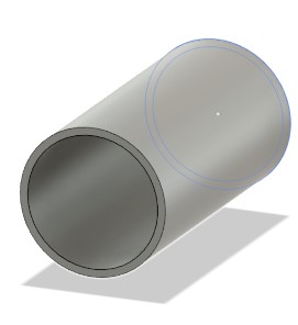
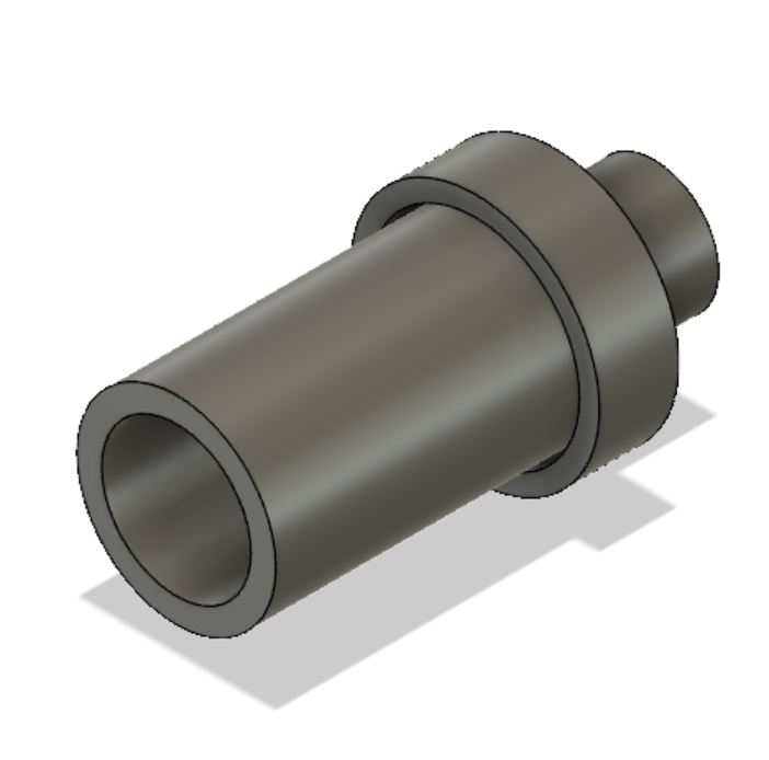
I began by making the main tube of the CPR mask.
Then, I researched check valves. This is the video that I watched that I ultimately based by design off of.
I also looked through my instructor’s website to see how to print an object within an object. (Mr. David Taylor’s site. He created a support that could be snapped off after printing allowing the ball to move freely within the confined space.
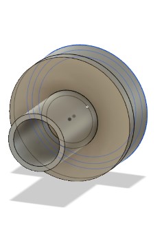
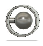
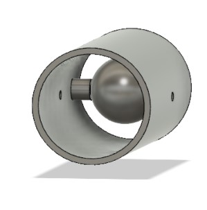
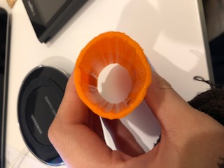
I created a sphere which would be supported by a pipe. These two components would be nested in a tube Once the print was complete, I would remove the support from the tube and ball. I also included holes for a metal rod to slide through. The metal rod would contain the ball within the tube. Finally, I created caps for the tube.
Tube:
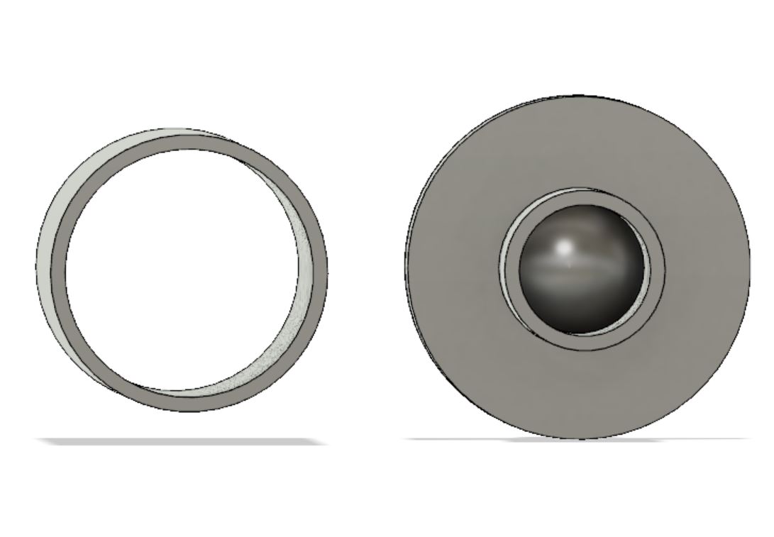
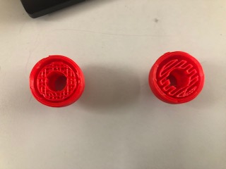
Caps:
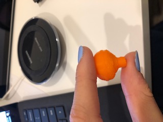
Sphere: I made sure to make my sphere small enough to fit inside the main tube, but large enough so it would not fall through the cap hole.
Support:
Rod Holes:
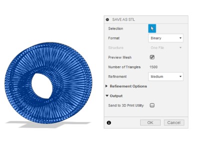
Once I had my check valve designed, I saved it as an STL.
Version 1:
After running my print several times, I found three major flaws in my first design.
-
My cap did not fit tightly onto my main tube.
-
My predesigned holes in the main tube were not being printed properly.
-
My tubes were collapsing on themselves. One sphere also did this.
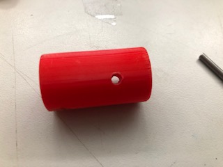
For my second design, I scaled the tube down, so that it would not have to support as much overhang weight. I also made the walls of the tube and cap thicker and removed the predesigned hole.
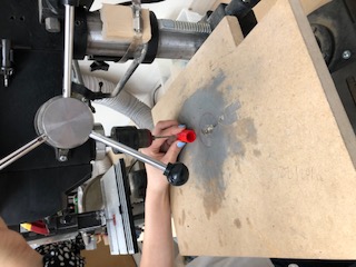
I decided it would be better to drill the hole after the print was finished so that the layers would not be uneven. If I were to use a bigger hole, I could probably still implement a hole in my design geometry.
My final addition were supports that could be calculated in CURA.
Version 2:
Printing
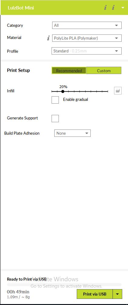
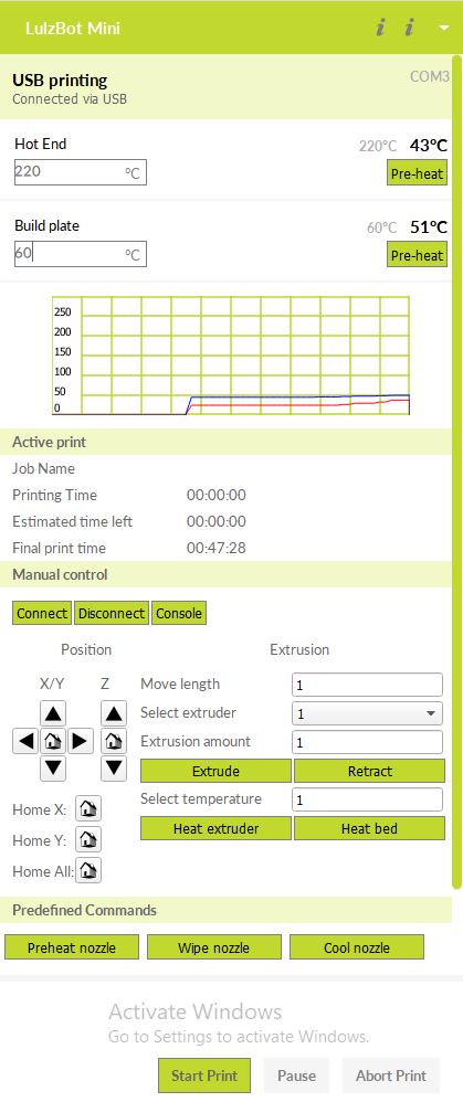
Then, I opened my STL in CURA. After, I turned on the LulzBot printer and connect it to the computer. I clicked on my objects and made sure they were orientated correctly. Finally, I changed the infills, adhesions, and set nozzle to 210 and the bed temperature to 60.
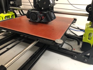
I prepared the bed by wiping off excess material with alcohol. I removed the excess material from the nozzle as well by extruding.
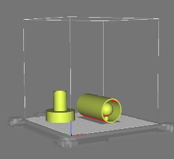
Here is what my design looked like in CURA: (This is my first version, so in the picture, you can see how large the valve is.)
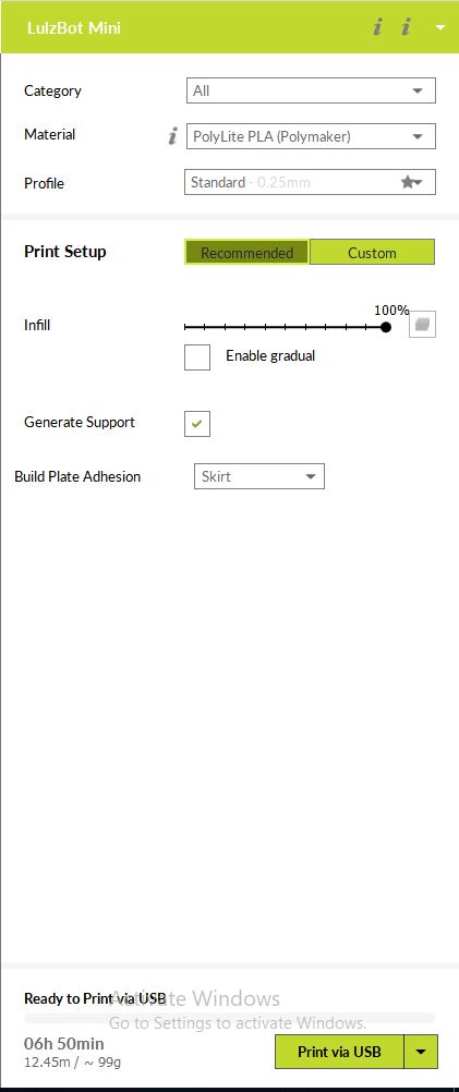
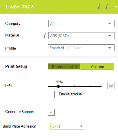
Here are my settings:
(I included supports for my final print)
These are a my failed prints:
- Too big and could not support itself
- Bed too cool (no adhesion)
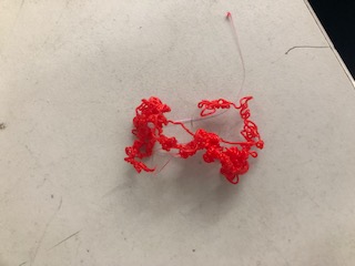
- Design flaws (cap too loose, hole causing problems)
This is what my cap supports looked like: One support was removed and fliped over to show the accordion connection.
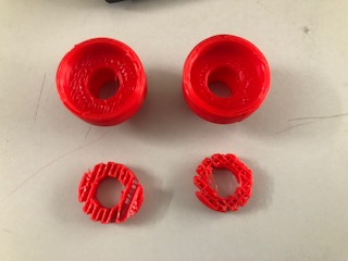
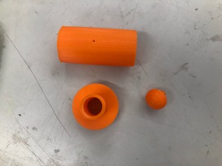
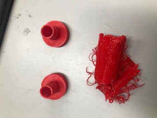
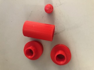
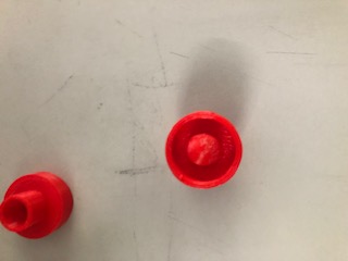
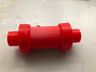
These are my check valve parts fresh off the printer!:
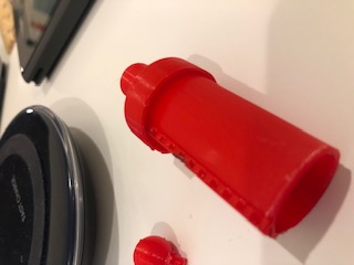
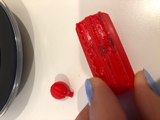
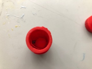
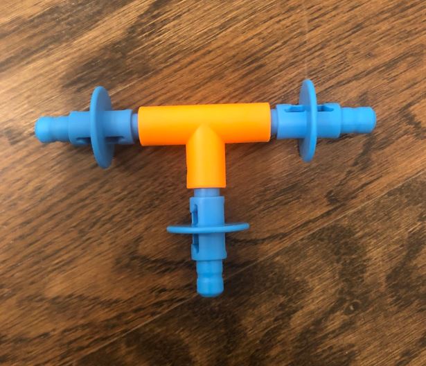
Here is what the check valve looked like assembled!: (I used a metal rod to fence in the ball)
Assembling/Testing
After reviewing my check valve with Dr. Fagan, I learned that I needed to fillet my cap edges because they were physically stressful. I also learned that I need to place a rubber ‘O’ ring between the ball and cap to create a better seal!
Scanning
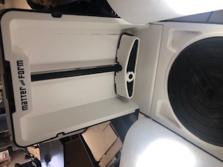
To familiarize myself with the scanning process, I read the Matter and Form manuel.
At Charlotte Latin, we use the Matter and Form 3D scanners.
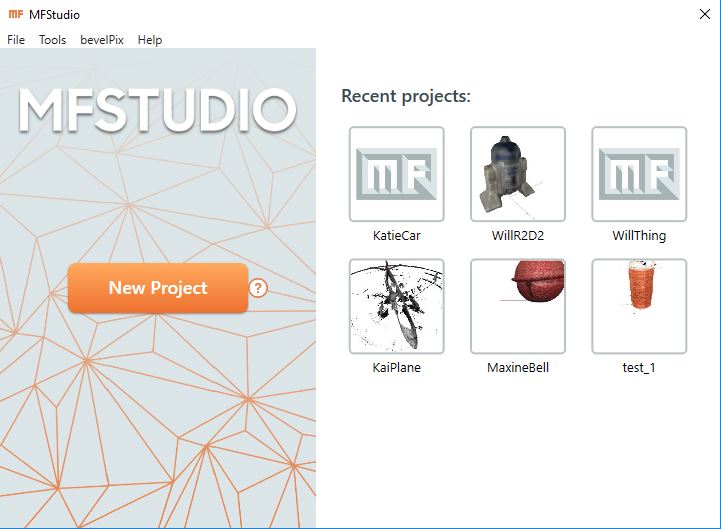
This is the software we use.
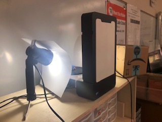
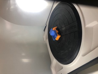
Lighting
Diffused white light or natural light are the best lighting conditions. If you don’t have good lighting, your scan will be inaccurate and you could even damage your machine. Here is my lighting setup:
Some materials cannot be scanned. This includes shiny, clear, and extremely dark materials. Luckily, you can paint or spray your object to make it more scannable.
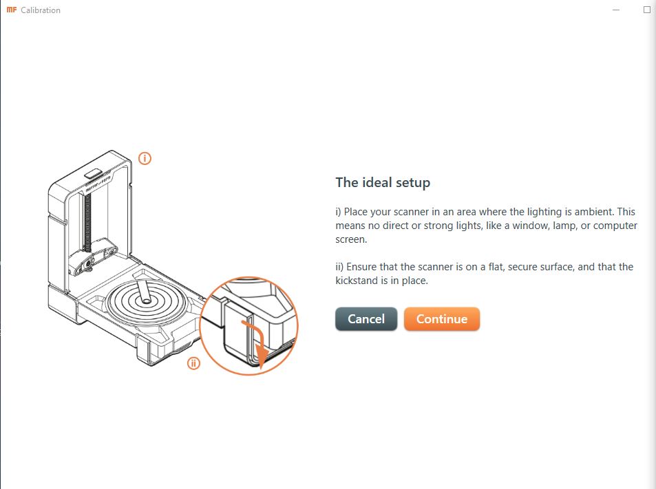
This is the starting screen of MFStudio.
Calibrating
Before scanning, I calibrated the machine.
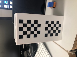
This is the calibration tool:
Calibration can also help the quality of your scan. It is important to calibrate periodically or when you drastically change the scanner’s environment. I learned that it was necessary to calibrate the machine even after changing something as small as the lighting. Calibration helps the machine gauge distance. If I did not calibrate the machine, my scan would not be scaled properly. Because I calibrated my machine, I ensured that my finished scan would match my origional object.
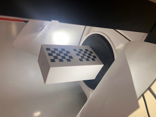
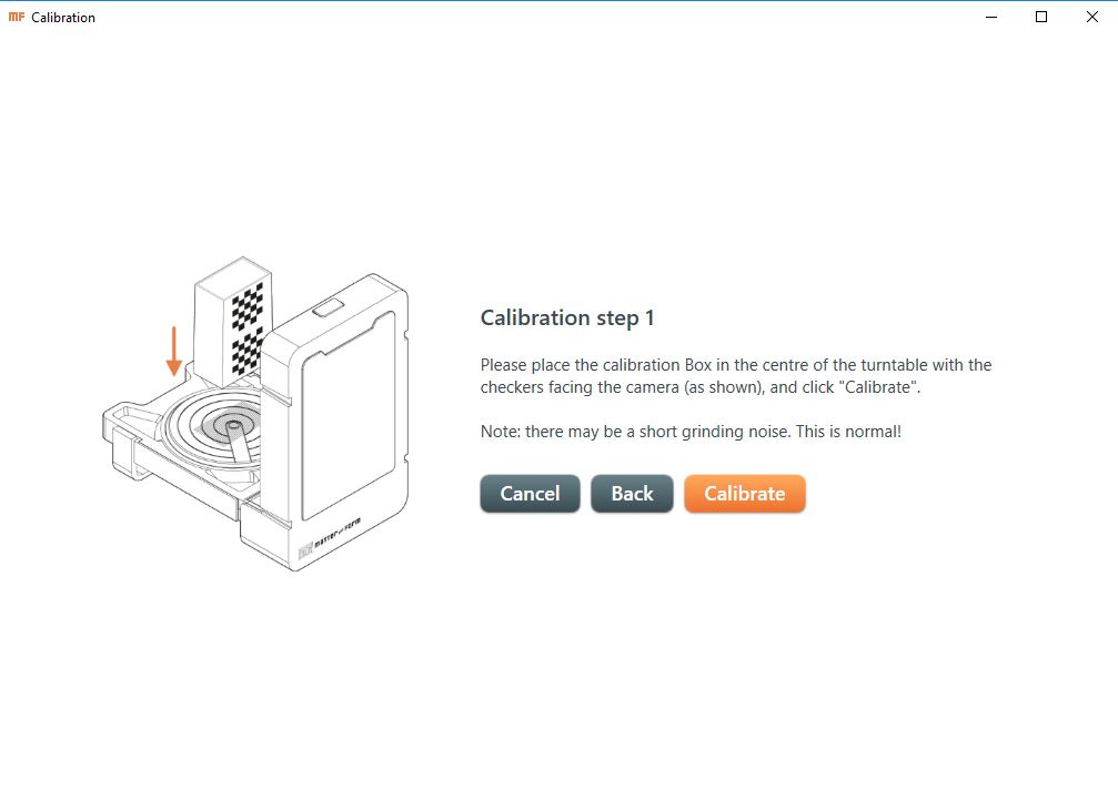
I startd by finding the calibration tool. At our lab, we have a rectangular prism with black and white checkers. I believe the pattern on the prism helps the machine identify the tool. Once I placed the calibration tool on the plate, I pressed the calibration button.
The machine slowly scanned the calibration tool while rotating the platter.
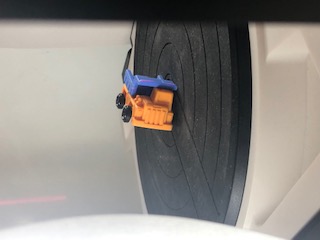
Settings
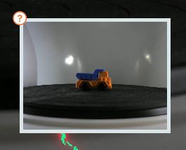
After calibrating, I placed my object inside and configured the settings.
There are two types of scans: quickscan and regular scan.
Quickscan used one laser. You will have the option to choose laser 1 (more accurate) and laser 2 (more coverage).
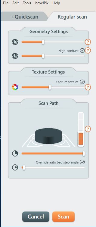
Regular scan uses two lasers. It captures geometry and textures. I decided to use this option for my 3D scan.
After choosing my scan type, I changed the laser exposure. This helped to decrease the laser “noise”. Dark colors need a bright exposure, while light colors need a dark exposure.
Next, I looked at the contrast settings. I used high contrast because the blue and orange on my truck where opposing colors.
Finally, I edited my texture settings. When changing texture, I tried to replicate the real life colors of my object.
Here are my settings:
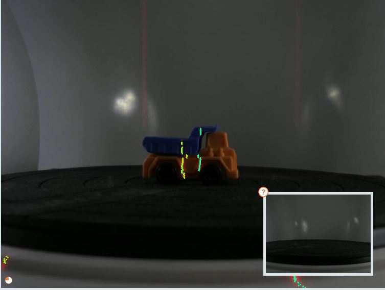
This is the visual result of my settings:
Remote Desktop
To work on my scan at home, I used a remote desktop set up by my classmate, Kai. He set up the remote destop throught the application, VNC Viewer. This allowed me to acess the compter we used for scanning to start new scans.
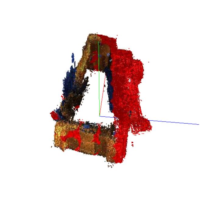
Scan Progression
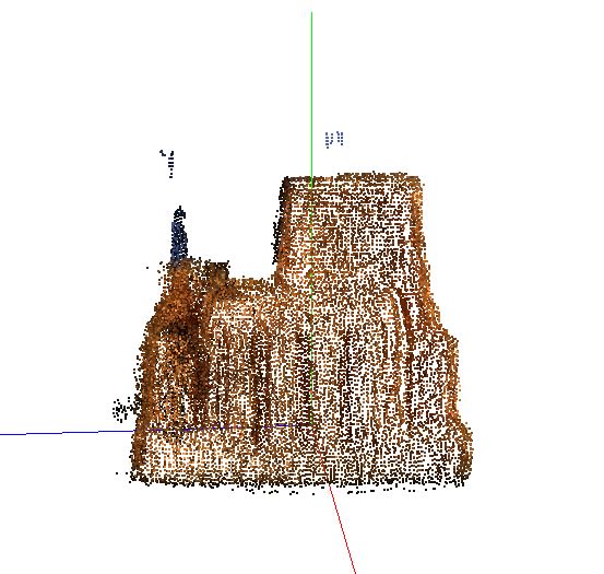
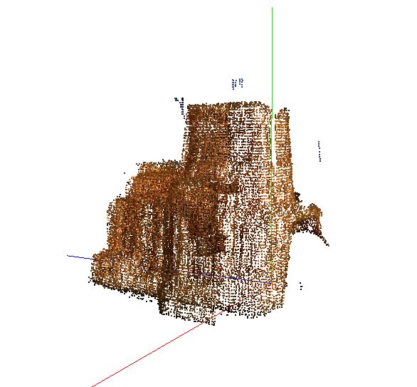
This is the how my scan proceeded.
Phase 1:
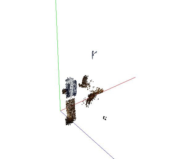
Phase 2:
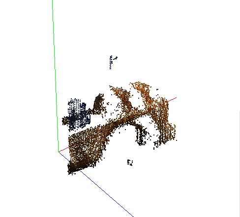
Phase 3:
Phase 4:
Phase 5:
Phase 6:
Phase 7:
Phase 8:
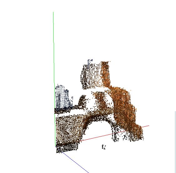
I ran my scan with 2 orientations to get all the angles.
This is my second orientation:
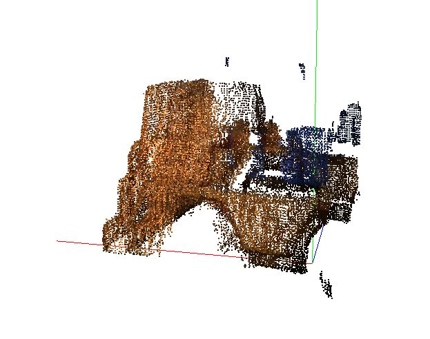
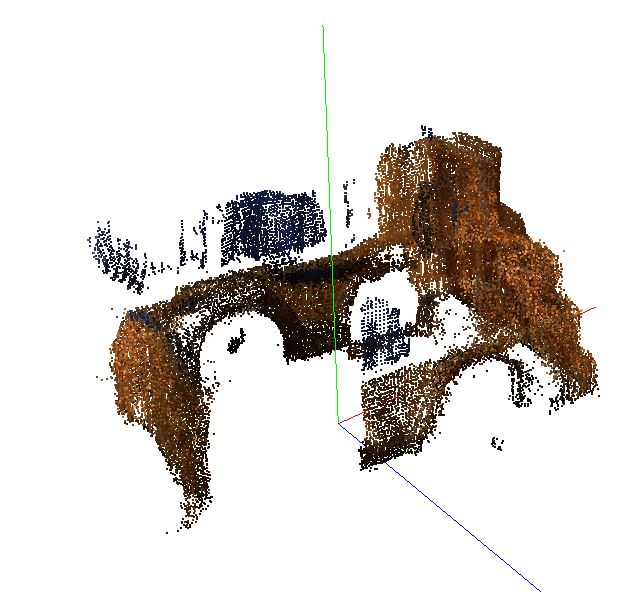
To align my scanning, I used the project editor. I wanted to align my truck top (blue part) to my truck bottom (orange part), but the alignment was not working. I tried selecting different points groupings on the different faces of both parts, but the alignment positioning only switched between two options.
Option 1:
Option 2:

I decided to try to mesh the parts separately, but because they did not have a complete top/bottom, their meshings randomly extended into the open space where the top/bottom should have been.
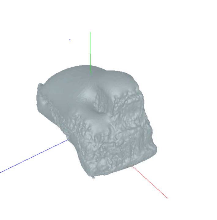
After considering the difficulties of the truck, I decided to switch to a different object. I choose to scan this blue Knex.
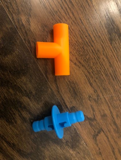
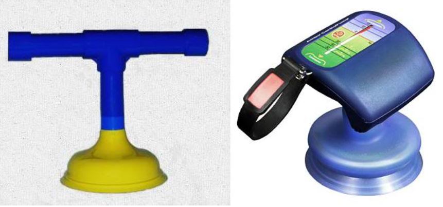
My goal was to start recreating the blue part of this CPR compression device.
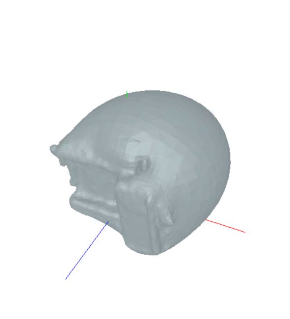
I again started by calibrating the scanner. After, I placed my object on the base plate and edited my settings.
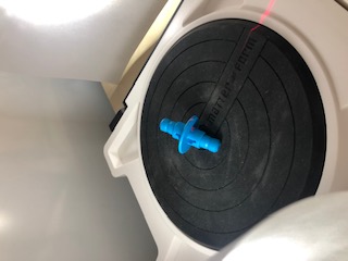
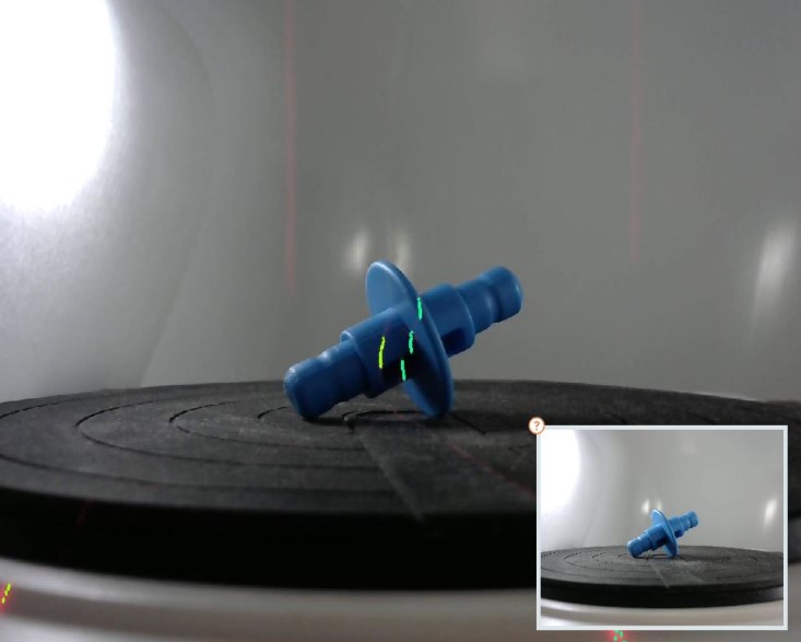
I found it was much easier to align the scans for this object because of its relative simplicity. In the end, I scanned the knex piece about 6 times and meshed it into this:
Advantages and Limitations
3D Printing
After experimenting with the 3D printer this week, I learned to consider the advantages and disadvantages of 3D printing when creating my design and choosing the printer settings.
One advantage that I found with 3D printing was the ability to fabricate designs that could not be developed with subtractive tools. With this advantage in mind, I was able to print out my check valve tube on its side. Inside this tube, I was also able to place my check valve ball.
While I was able to print these more complex designs, the quality of the prints were not as clean as some of the other technology in out Fab Lab. Throughout this week, I experienced many failed prints that would collapse on themselves or extrude incorrectly.
After many of my prints failed, I started adding supports to my design to improve the outcome. This dramatically improved my print quality.
Unfortunately, with the addition of these supports came an addition of manual labor on my part. I would often struggle to remove the supports in the middle of the tube as they were not as easily accessible.
Overall, I found that the advantages of 3D printing far outweighed the disadvantages.
Design Specificity
The biggest advantage of 3D printing was the actual ability to fabricate my component. I had to print my check valve on its side because of the ball that rested inside my check valve. Without 3D printing, I could not have produced this piece in this relativly easy manner. I was able to print a tube (which has overhangs). I was also able to print the ball (which was nested inside the tube). If I had manufactured this component with a subtractive method, I could not have printed the check valve sizeways with the ball nested inside.
Scanning
Overall, I thought the scanning process was really cool! I liked how the machinery would capture the abstract shapes and curvatures of the object that I was scanning. It was also interesting how the machine would play with lighting to produce clearer images.
While I appreciated these aspects of the scanner, I was disappointed with the lack of detail that the machine would produce. Especially with my truck scan, many smaller details like the wheel divots were missed.
I found out that this was due to the coloring of the wheels. Because of the was the scanner worked, black materials, clear materials, etc. could not be scanned. This was unfortunate as my first object had a black bottom.
I also found that the scanning process took an extremely long time. It would take multiple hours to complete one scan. It took me almost a day to scan my entire truck.
With these pros and cons in mind, I concluded that the scanning process was not as useful as the 3D printing process. Still, I would be interested in looking into more advanced or updated scanners in the future.
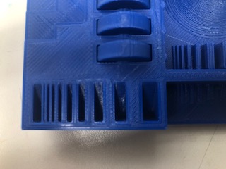
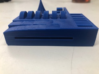
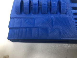
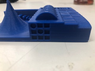
Group Assignment: Test the design rules for your 3D printer(s)
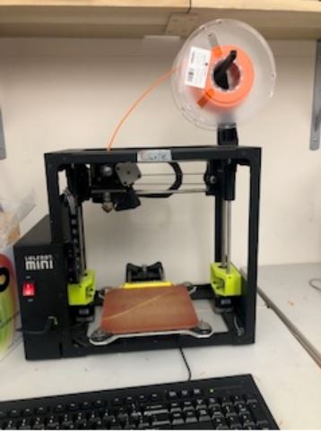
For our group project this week, we tested the capabilities and constraints of our 3D printer, the LulzBot Mini.
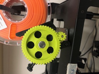
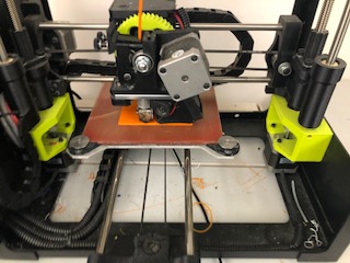
Here are some pictures of the inner parts of the printer! Extrusion Motor:
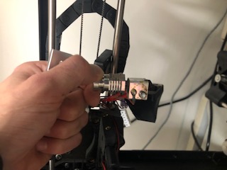
Hot End:
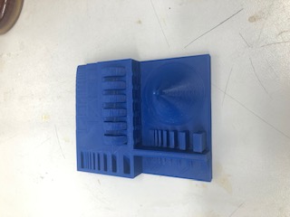
First, we choose an object to print. This is the recommended 3D Printer Tolerance Test by Amanda Ghassaei.
We used CURA to print the design.
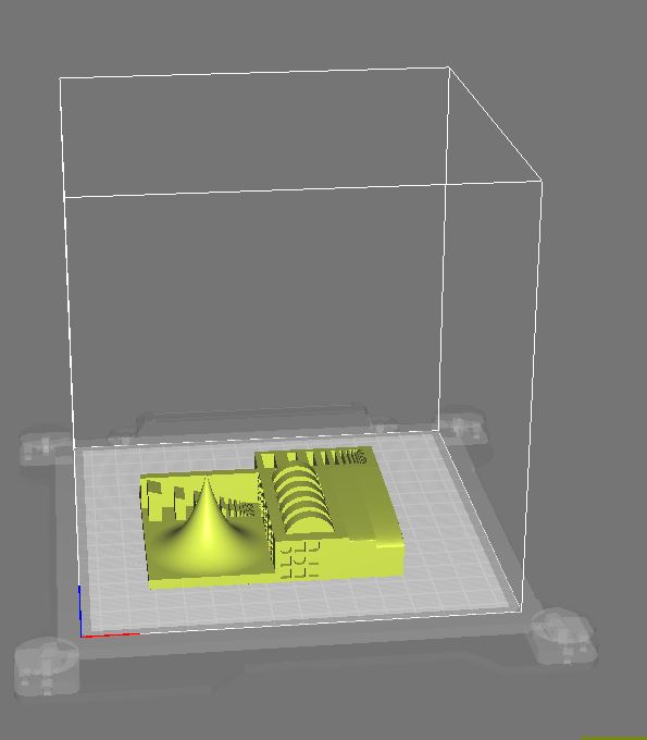
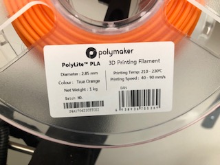
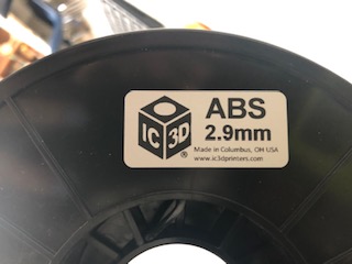
Using her design, we went through the printing process for our Lulz Bot printers with PLA and ABS.
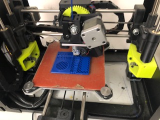
We printed three varients of the design.
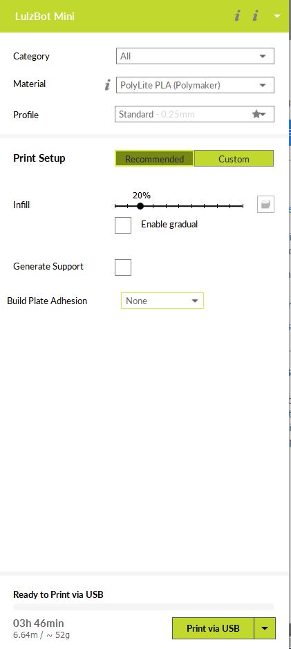
- PLA with 20% infill
Settings:
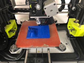
Progression:
- PLA with 100% infill
Settings:
Progression:
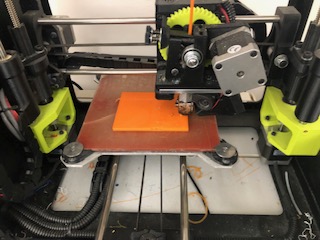
- ABS with 20% infill
Settings:
Progression:
I found that the 100% infill PLA test was unnecessarily long and took too much PLA. The ABS was tricky to work with because it required the bed to be set to a higher temerature to keep it from from warping.
Here is a video of the ABS print stopping due to a computer delay:
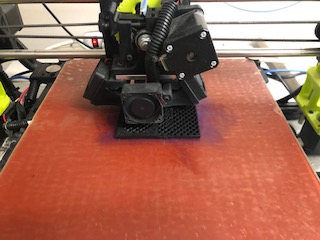
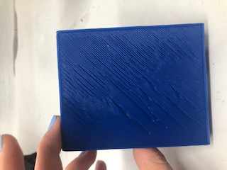
Here is a picture and video showing the poor ABS adhesion:
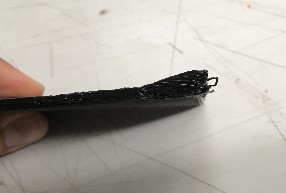
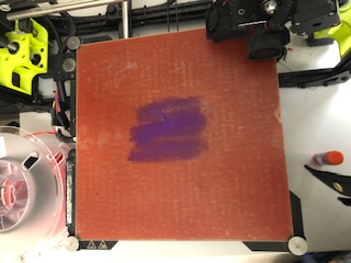
We tried to fix this problem by applying a layer of purple glue to the bed of the printer, but the ABS still lifted up slightly.
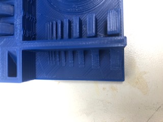
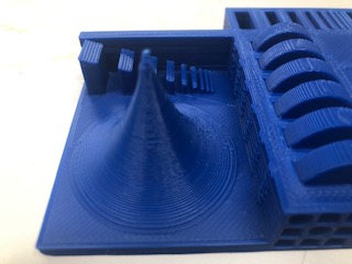
Our one sucess was the first PLA with 20% infill!
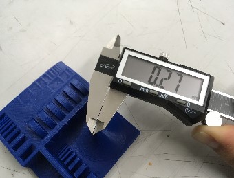
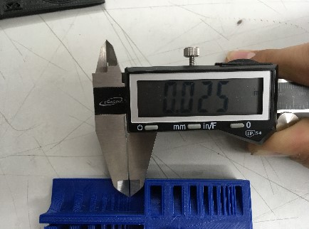
Here are some pictures showing the capabilities of the printer!:
Files
Here are my STL files: Download Files