Electronics Production
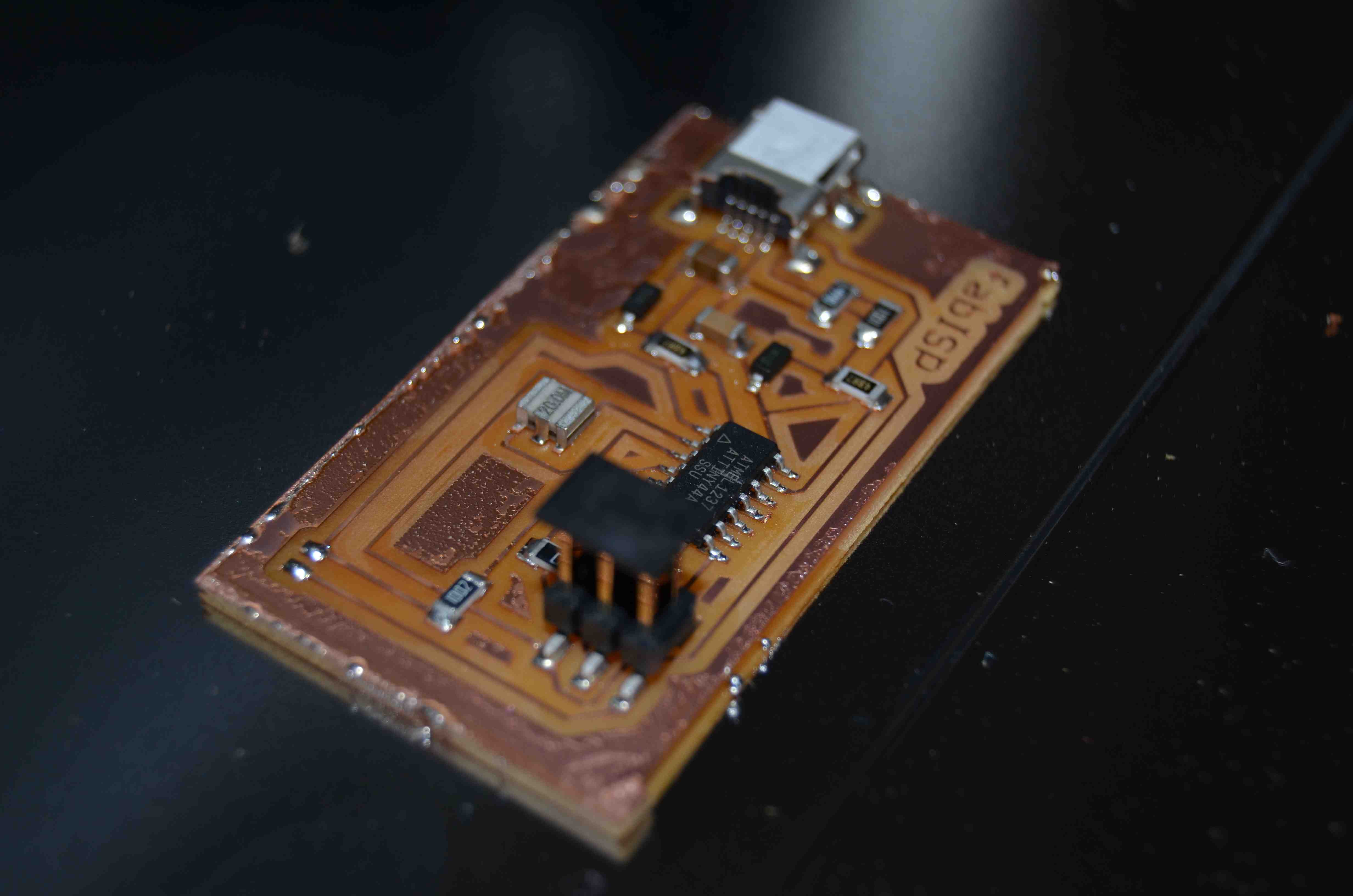
FabISP: Making an electronics board that can program other boards
Using the fab modules, armed with both Mercedes and her old tutorials to make sure I don't break any bits, we went boldly into circuit board milling. We didn't run into many problems. We even tried some old solder paste. It turned out pretty well. It was my first experiment with solder paste, though I have milled boards before, and I have helped other people make masks for solder paste with the vinyl cutters.
I also used the very complete tutorial on the fab academy archive Mercedes made a few years back in 2011.
Load and Edit the board in EAGLE CAD
Start with an EAGLE cad file from the course files. Jeff took that and edited it to use a single resonator instead of a crystal plus two more capacitors. This is the same as the updated board for the class, but we couldn't find the eagle files for that one. Now they exist. yay! Export and re-save/export the images through Inkscape or Gimp. Double check before you save that the dimensions are right. You can check dimensions of original images reliably in many programs like Preview and Photoshop. For some reason the png's from EAGLE aren't readable by our version of the fab modules but if you re-save them they are.
Edit for fun and also usablility of end-device.
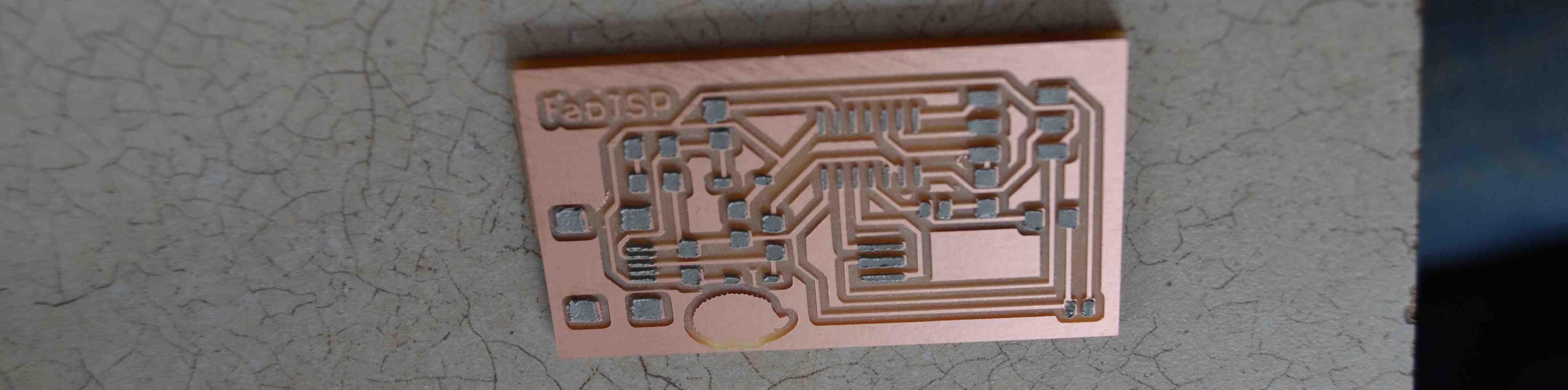
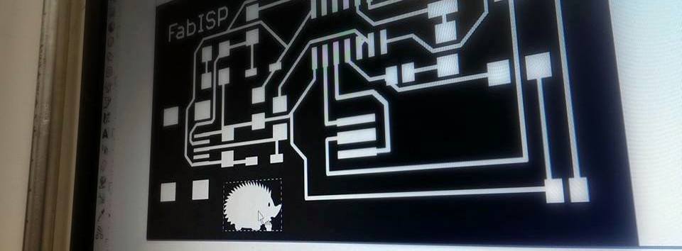
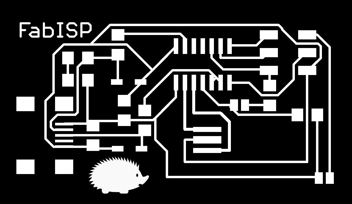
Depending on what you want your final shape to be, you may want to do the final edit in your favorite graphics editing program, because EAGLE isn't made to easily draw or import images into. This is how we put a little hedgehog onto the corner of our board, and save an outline that would definitely go outside the hedgehog. The board area should be white, and the area to be cut away outside it should be black (though that is also a setting you could toggle in the fab modules).
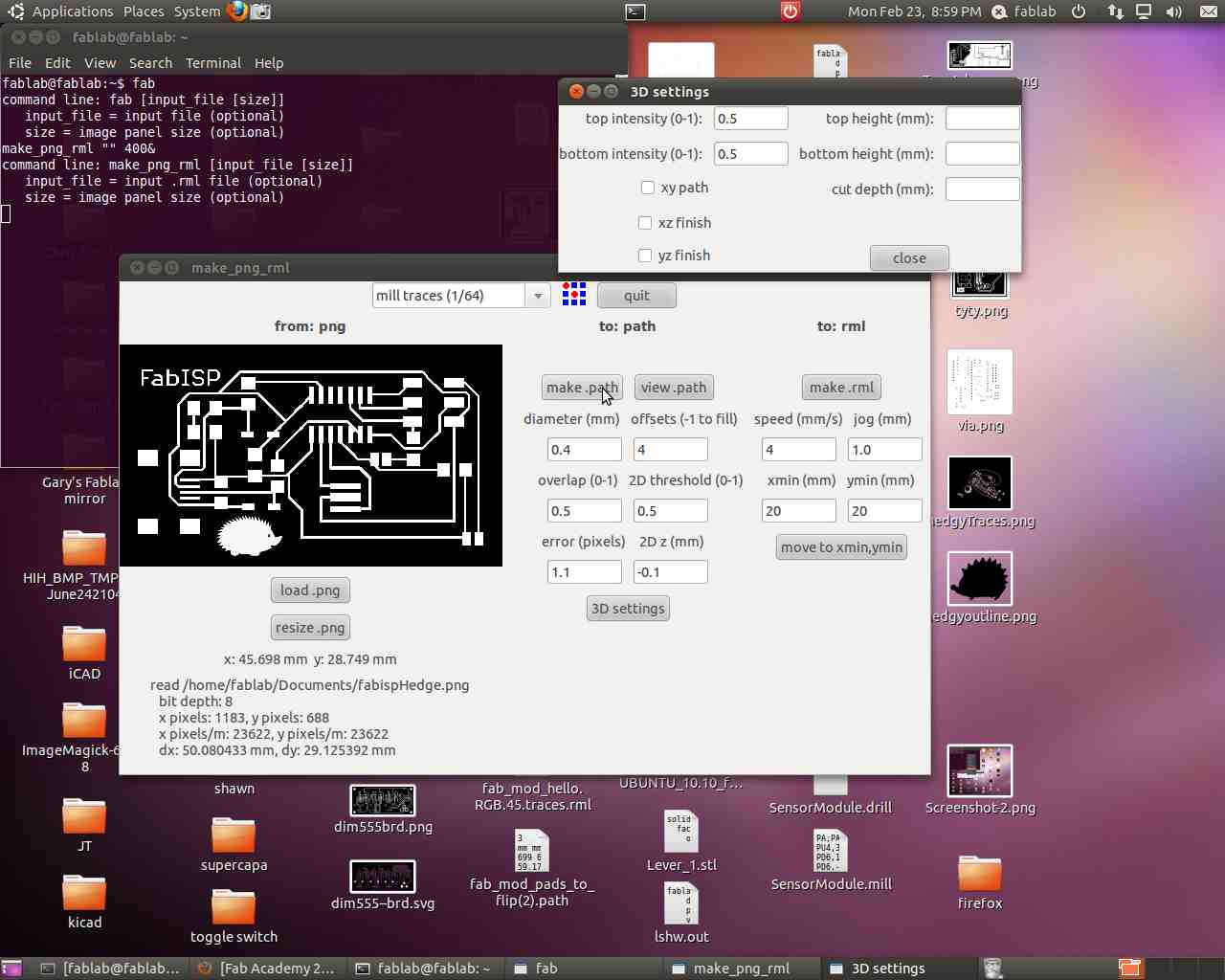
Open the fab modules
Open a terminal in Ubuntu. Type "fab". In the first window select .png as input, and .rml roland modela as output. Click "make_png_rml"
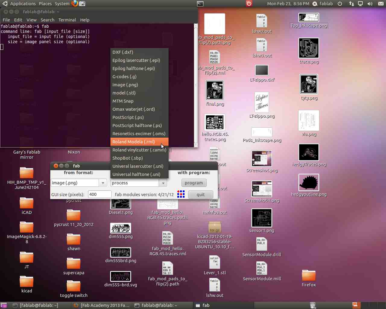
This will open up a new window that will control your machine. (We'll assume you already have the modela set up and the fab modules talking to it. You need to do some things to change default USB behavior to set it up the very first time with a new computer.)
Prep your board
Clean your board w/ soap and water. Place a sacrificial board down. We swapped out the mdf board I've been using since Mercedes thought it's gotten a bit cut into and doesn't look all that flat anymore. So, the sacrificial board now is the bottom of one of our new 3'x5" pcb boards, copper side down. It's secured with six parallel strips of 1/2" double stick tape. I've used carpet tape in the past, but that's hard to get up. We use normal 3M scotch 2 sided tape.
Mill the board
In the fab module select the defaults for Milling with a 1/64" bit. Change the bit if needed. Use just one set screw and be careful to hold the bit while loosening it so that it doesn't break when it falls. Click load png, select your image file of your traces.
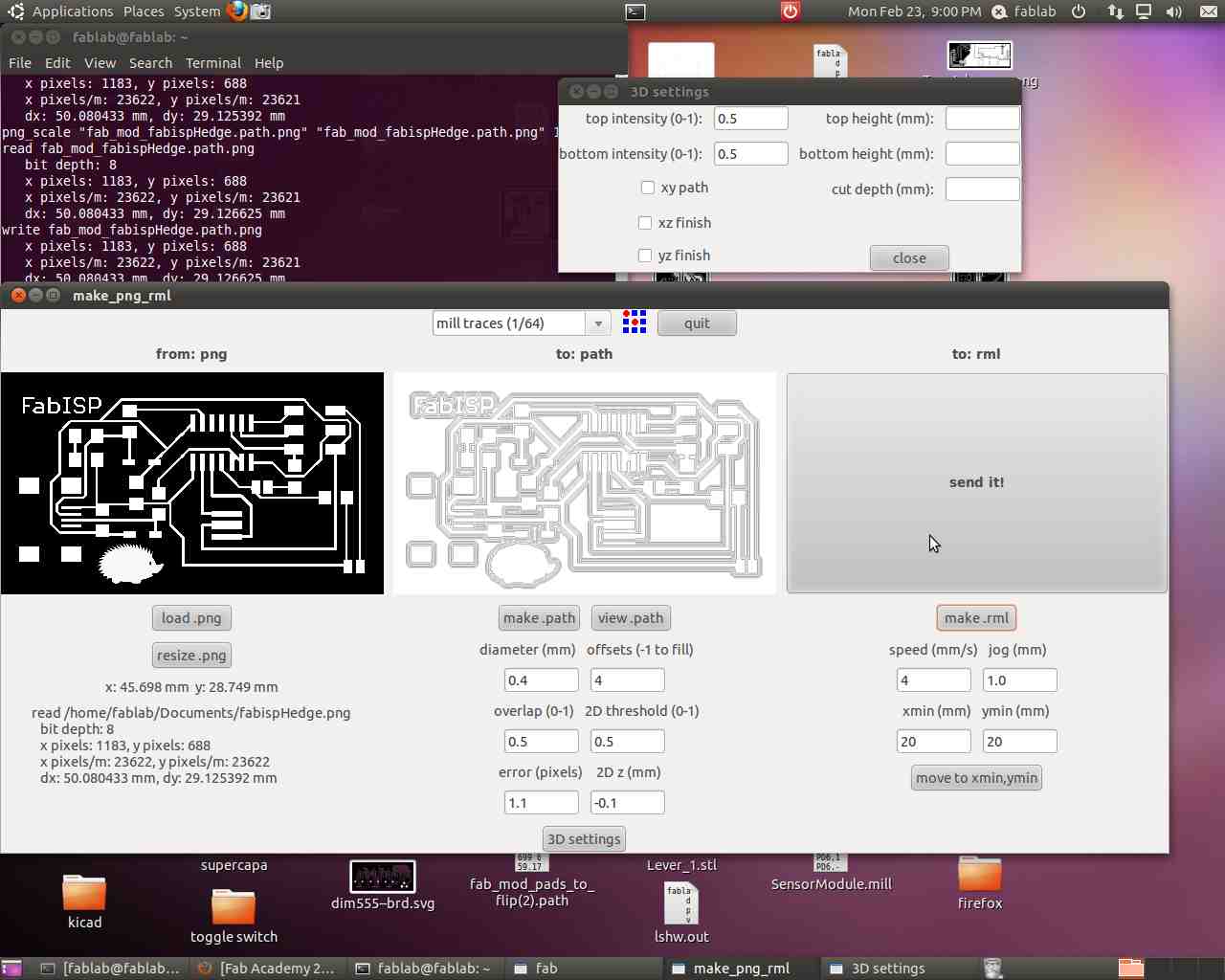
Use move to xmin,ymin to zero the bottom left corner on your board. The bit will move to the corner. Check to make sure this is where you want it to start. Adjust xmin, ymin, and try again as needed. While stopped, loosen the bit and let it rest on your board. Tighten the bit again. You have now zeroed the z-height. Yay! Check settings, Click make .path, Click make .rml. Offset is how many times you want it to cut around your paths. The default 4 is good. 2 - 3 is faster and fine, but might require a finer hand because copper will be closer to your traces. Make sure everyone around you has safety glasses on. Click "send it" to start the board milling. Replace the safety plate/sheild.
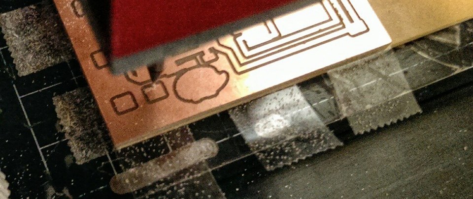
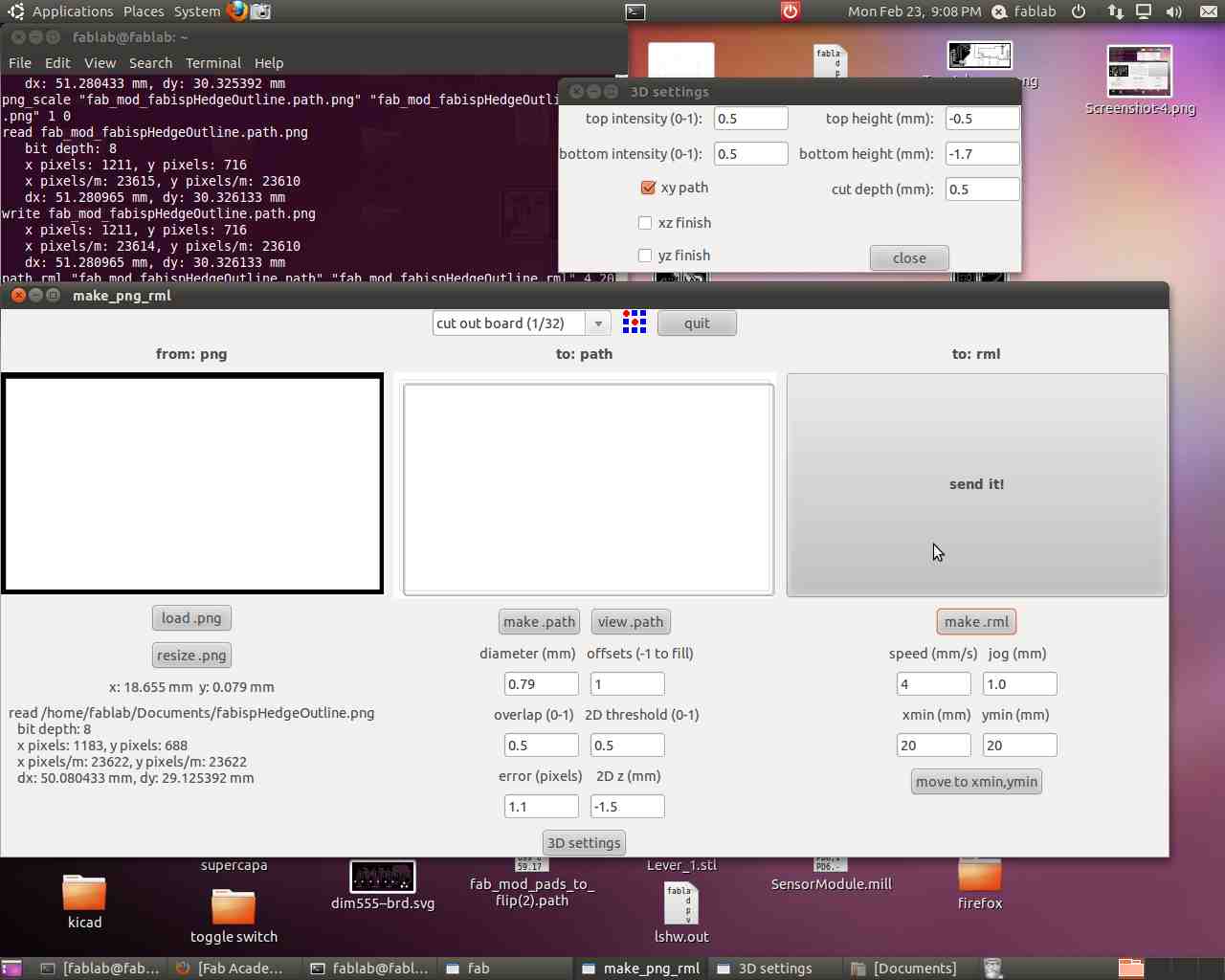
Cut the board
In the fab module select the defaults for Cutting with a 1/32" bit. Change the bit. Re-zero z-height. Tighten the bit, don't over tighten the set screw. Set z to -1.5. Don't change other things. Click "load png". Select your file of your board shape. Click "make .rml". Click "Send it!" when you're ready for it to start milling.
Solder components to the board
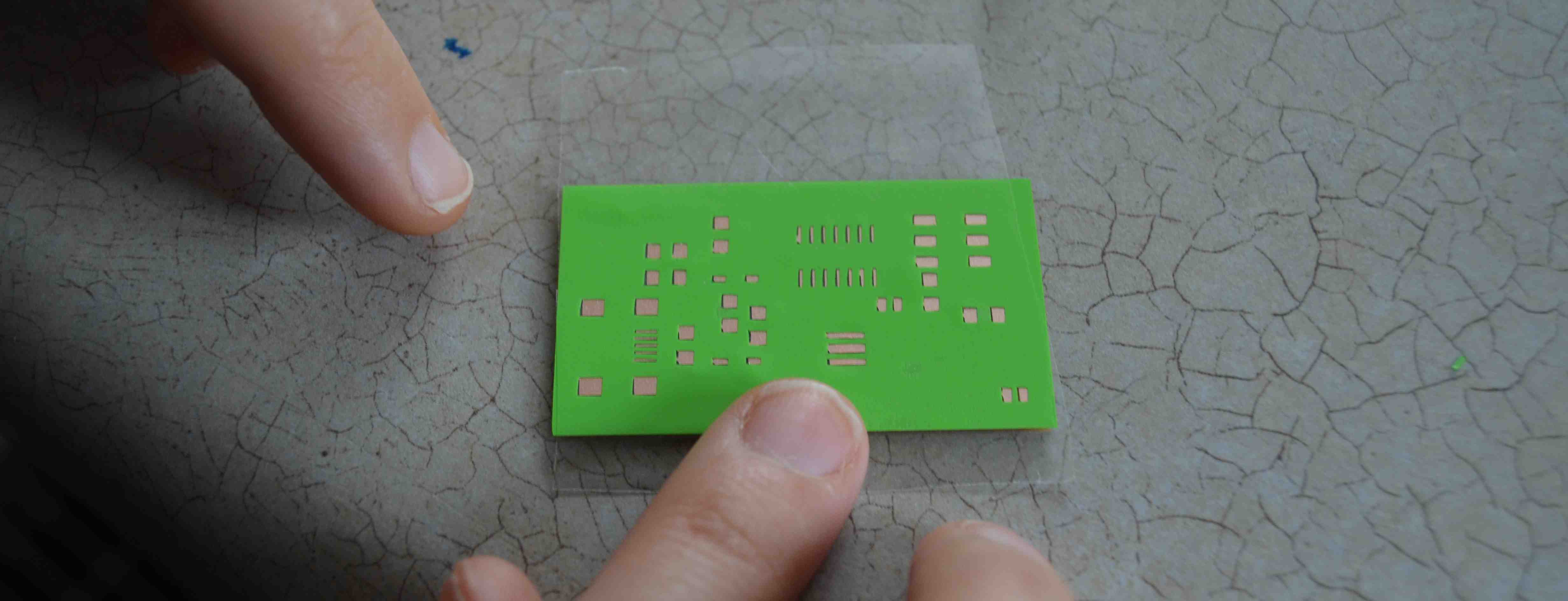
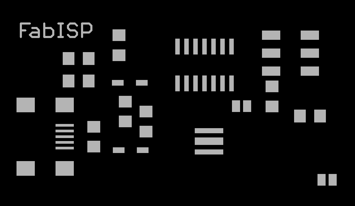
I took Jeff's eagle cad file with its slight alterations to make a mask with. Mercedes showed me how to rip up all the paths for a quick and dirty way to get just the pads with the ripup; command. Type in commands in the line at the top of the board layout window. The red on black was still not enough contrast to trace, so I re-exported a png after changing the traces to light grey. The better way I've discovered since then is to use the export as greyscale option in Eagle, rather than just change the color. Imported into Silhouette studio (which, of course, always gets the size wrong no matter how I change the default options--so I used gimp to tell me what size the outer square was supposed to be and resized to that in Silhouette). I then traced it using low threshold and the scale all the way down (4 is as low as it goes) to prevent it from rounding the corners. It has the weird behavior of being dimension sensitive--so if you blow up the image, then trace it, then make it small again, you'll get better fidelity. That usually isn't needed, but just fyi.
this is actually Jess's board, but mine looked pretty similar! I just wanted to point out that we put them in our nice (not for food) Cuisinart toaster oven at 475F. It took a few minutes to reach temp. Once all the joints are shiny instead of matte or dull, then take it out pretty much straight away to avoid delaminating or burning the pcb. It also helped to put it on the corrugated instead of flat pan to reduce the heat transfer from the bottom. Later, I would set it to 450, and only then switch it to 475/500 so that I would have warning and be watching more closely when it reached temperature.
Program, and use the board to program another board
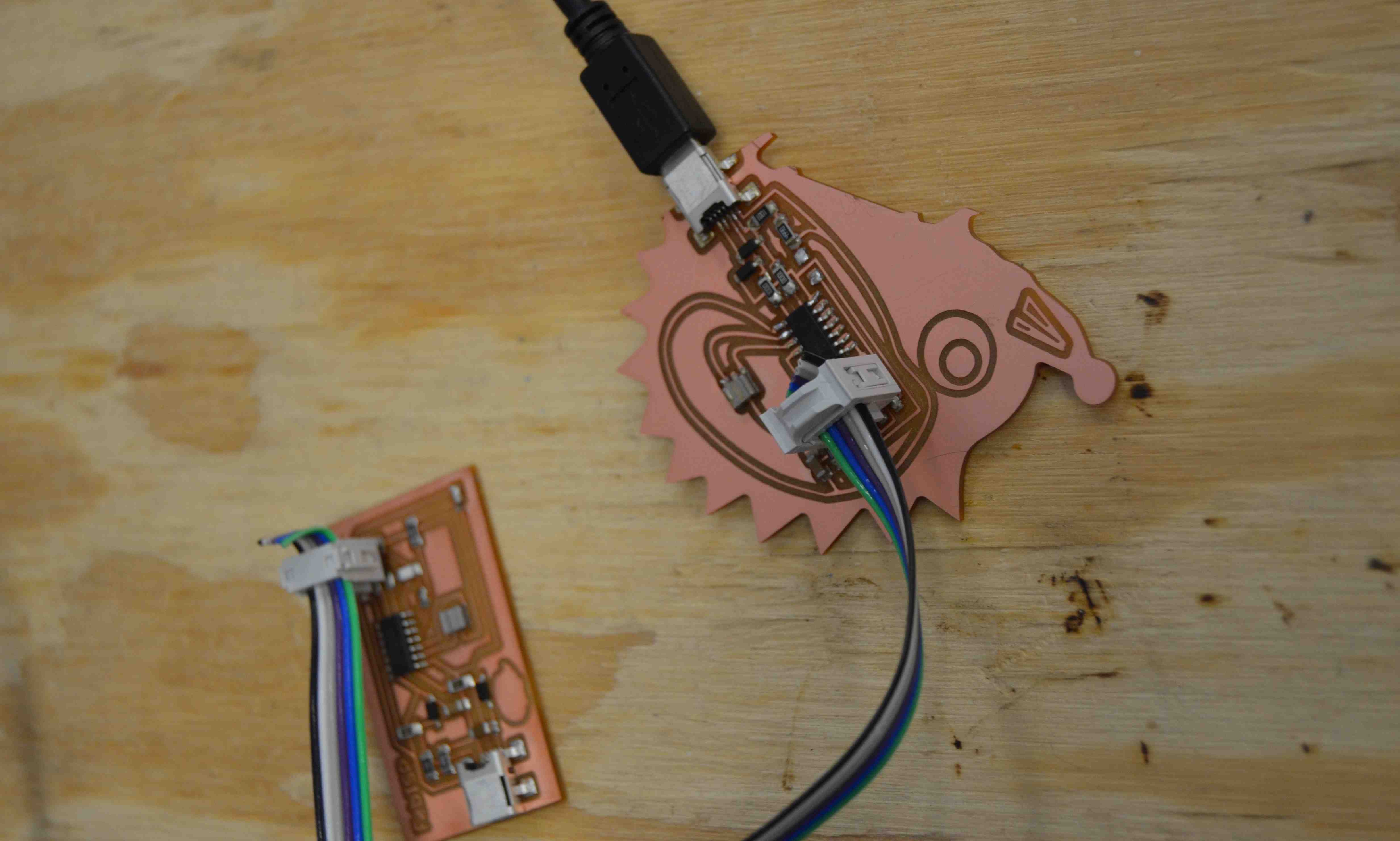
We had some trouble getting out fancy new programmer (atmel ICE) to work. So we ended up using a cheap one we'd gotten from sparkfun that Colten and I have used to program bare breadboardable ATtiny's before. Maybe we were just picking the wrong programmer in the software (our first guess was the mkII isp, but you know, it could have been any of the ten jsen options perhaps), or maybe our ICE board was shoddy and had some loose connections, I'm still not sure. The programer is on a line that looks like, "AVRDUDE = avrdude -c avrisp2 -P usb -p $(DEVICE)". Once you've got a FabISP working, you'll want to change the programmer line to something like, "AVRDUDE = avrdude -c usbtiny -p $(DEVICE) " instead. You'll also want to set your clock (20MHz, or whatever you used) on a line that looks like, "F_CPU = 20000000" (set the number to your external resinator speed). Once you've got the programmer and clock set correctly, you can run the commands (in a command line): sudo make clean, sudo make hex, sudo make fuse, sudo make program. But once one fabISP was loaded and working we could de-solder the jumper and use it to program another! We had one extra board Jess made, so everyone got a chance to use their board to program another person's. Fun fun!
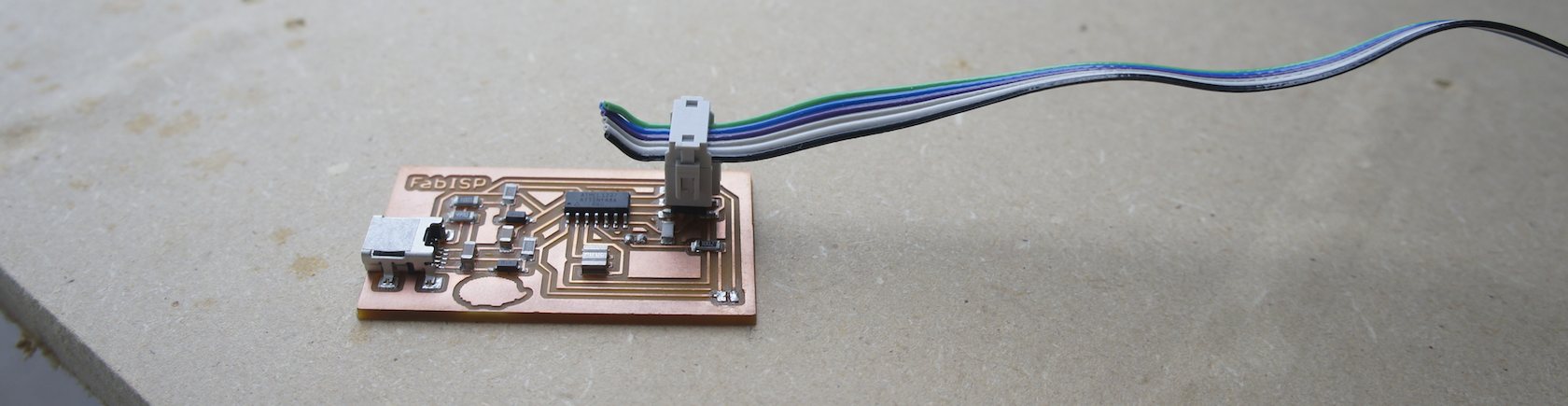
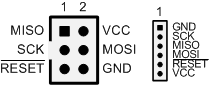
And for the record, to use your FabISP, you need a mini (not micro) USB to the computer, and then the ISP headers are set up in the standard way. Micro USB is nice because it's small and these days ubiquitous, but the pins are much closer together and thus a bit more of a challenge to solder and slightly more likely to mechanically fail over time from the copper delaminating/pulling up. If you look at the board Hedgehog standing upright, then ground is the bottom right pin. the rest are: