Final Project
A make-your-own 3d printable wrist brace program
and a temperature controlled cooling fan
Want to skip to the tutorial?
Some basics first
I sometimes (often...!) dislocate my wrist and I've found that traditional wrist braces are lacking in a number of ways. They are ugly, cumbersome, ill-fitting, and most of all extrememly hot to the point of increasing rather than decreasing inflamation. I wanted to do better. This is that story :)
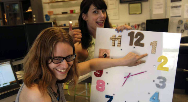
I bring it to you here in a series of posts, to read backwards if you like, of my progress on the project. If you want to skip to the end you can--go read my tutorial on how to make your own instead! It will appear after the parameterized design work is done... which it's not yet. It may be a work in progress and become "good enough" at some point, and then I'll fiddle with it more. Here I am getting inspiration from Jess's time to make things clock.
Updates
UPDATE 1: I am leaning now towards making a wrist brace for my perpetually dislocating wrist (boo!). In the summer braces are stifling. I would like to 3d print one that wraps my arm perfectly in an open frame. Possibly cover it with something soft and silicone-like. Add a strip to cool it, and something to regulate the temperature both auto-chill, and off on demand. Possibly make it run off battery power recharged by a vampire circuit controlled solar panel… but I’m not sure that would produce enough juice. I’m going need to play a bit more with solar if I want to include that. If I get it working and have some time, I’d really love to make the thing parametrically generate a brace for any STL you load, so that people can make their own with very little fuss. (At least the brace part, if not the electronics additions)
UPDATE 2: learned more about how to hold a wrist for the best brace. Will re-3d scan it in a better area. Will cut it up and do a Voronoi reduction on it (or something similar) to make it light and not hot. Then cover in rubber or silicon to make it soft, leaving the thumb side open to make it easy to put on and take off. I wanted to cool it with a peltier cooler, but I may not be able to fit enough battery power on my forearm for that to be practical! So I may go with a fan triggered by temperature instead. I have make similar boards already that sense temperature and control motors, so I know that they will take less fiddling around with. Somewhat disapointing though.
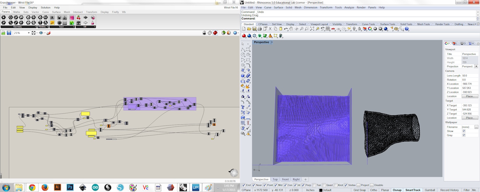
UPDATE 3: Played around more with rhino and grasshopper, and some plugins for them. Played with importing the 3d .stl files and figured out how to get an outset on a mesh ("Mesh" is their terminology for the sets of joined points, as opposed to a "surface," which is a set of equations and thus can be more easily manipulated mathematically. Some 3d programs use the same terminology, others do not.) Figured out how to cut the mesh, and also how to discard the chopped off portions. Stuck for a long time on how to join the two meshes. Played around with making planes paremetically based on the .stl that I import. Added some parameters to control the planes positions and the thickness of the outset by typing a number into a box or by moving a slider. What I want to do is be able to have someone scan their wrist, and with as few entered parameters as possible, be able to create a file for and 3d print their own version of my design for their own wrist and purposes. Fasion or function.
UPDATE 4: Worked with a really experienced grasshopper/rhino enthusiast/achitecture student and learned a lot. Jon showed me a way to fix my problem creating a solid from surfaces that I brought in and also answered all my questions when I wanted to add new features like a rounded edge on the cut side: one way is to create a fillet along the intersection of a plane, position set parametrically and the wrist scan, make the radius a little bigger than half your brace, connect it to a bevel on the otherside, and subtract that from the solid version of your brace. Which is to say, you can see it in my new code, and it's a bit hard to describe. He also suggested some new plugins that he finds handy which I'll check out more: wb, lunchbox, and one more I'lll remember later.
UPDATE 5:
Project management & organization: answer these
What will it do
It will stabilze a wrist comfortably, and without heating, and turn on a fan when it's warm. It will be art or at least fashion, or at least something that declares nerdiness with a modern, post-calculator watch era. Anyone should be able to scan their wrist and produce their own printable version unique to themselves.
At least anyone with access to electronics production tools (or a board house), a 3d printer large enough for the size of brace they want, and Rhino software. And bits of money and time, as with all projects.
Who has done it before:
- Adafruit. It's a printable on thingiverse that you print in PLA flat then wrap it around after heating in hot water. I'd like mine to be 3d printed more exactly based on a scan, but I'd like to experiment with using PLA and more closely fitting it afterwards. Read more on their post.
- AnphibianSkin offers a similar product for $200, but it is not open source it appears. The 3d printer company they use also has a write up on their blog.
- Bitrebels has another, much closer to my plans, but the designs aren't easy to find. In any case they don't incorporate outside cooling...
Overall, it's not a novel object physically, but it looks like no one has done it in the way I would like to yet! So I may as well go ahead and do that. Though I'm most excited about getting the brace that is cool, fitted, it's also significantly different to add a temperature controlled fan, or a fan of any sort. I hope that's because it's tricky and maybe because it's hard to make it not look weird and not because it's ineffective at cooling. I'll have to see! :)
what materials and components will be required?
a kinect scanner or other 3d scanner, computers with various software, Roland modela with 1/64" and 1/32" flat bits for routing the boards. a 3d printer (possibly best with a TAZ, or similar large printer that has a tall clearance for a tall print). A silhouette Cameo electronic cutter and a nice toaster oven (for solder paste), plus some soldering irons and related equipment for testing and fixing if and when something isn't working on them. Low temperature hot glue guns and tape for testing positioning of boards and batteries on brace. Velcro, fabric, straps, and other potential connectors to test for the ones I want. One sided copper sided boards soft enough to mill (sourced from Inventables). Electronics from digikey and wire from amazon or scrounged. Surface mounted parts: 21LEDs, capacitors, resistors, ATTINY 45s and 44s, headers, a switch, a voltage regulator (BOM below). An ISP/programmer and FTDI.
where will they come from?
From the fab inventory, and our fab lab tools, plus a small fan from an old computer. And wrists from myself and people around me.
how much will it cost?
Well, that depends on what you count, but < 10's of dollars for the prototype, assuming access to all the same tools. Under $10 for the 3d print (assuming it works the first time, or ~$20 if it takes a several tries and is somewhat large). Fans can be scavanged in theory, as could a few wires, and the boards can be cut from a single blank, and the thermister, ATtiny, and other electronics parts are under $10, even with shipping from digikey. The real cost is Rhino, if you don't have free access to it. But currently, as of July 2015, Rhino has a generous 3 month free trial period.
what parts and systems will be made?
a physical enclosure: a 3d printed wrist guard. An input/output board system with attached battery.
what processes will be used?
2d modeling, electronics design, 3d modeling and parametric modeling, electronics production and programming for input and output devices, sewing...
what tasks need to be completed?
Produce the 3d model. Produce code that is easy enough to use that others can print their own based on their own imported design and a few simple (hopefully simple) entered parameters. Assemble the electronics, and try out the fan, or a few fans.
what questions need to be answered?
How best to print it (maybe on our TAZ with PLA, pointing up...). How to make it rubbery (SiOx? Rubber? something painted on? dipped in? Just leave it as a hard brace?) How to make a side open to make it easy to take on and off, and what closure to use on that side. What temperature to turn on the fan, what speed to run the fan at.
what is the schedule?
Do electronics and parametric modeling this next week and a half. By the end of the month have a printed brace, and the electronics to go with it. Integrate them in the next week. Finish early, leaving a week for editing the code to be more easily usable by others to create their own braces!
how will it be evaluated?
How does it feel? Does it break when taking on and off? Does it keep the wrist comfortable? Immobile? Cool? Does the fan turn on and off when the temperature changes? Update: the fan is much more effective at cooling than I'd expected! The brace seems very sturdy even after putting it on and removing it many times. It could be more comfortable, but it's pretty good, and I think I'd go with a tighter fit, or perhaps coated in rubber next trial run. Evnn without the fan it's far superior at staying cool than any standard brace.
Thoughts about licence
I've had discussions with friends about which licences are too restrictive, and what may or may not protect any work from being copyrighted by others in ways that then prevent their continued distribution and use in the community. And also not scare people away from using it, which sometimes any copyright does (which makes me like the copyleft movement which I found out about form one of its staunch proponents, Nina--also an awesome artist of many mediums). I should probably talk to one of my patent lawyer friends about it sometime... I'm sure there are a facinating number of variations and intricacites. But for now it seems like this creative commons licence pretty well sums up my thoughts on the matter:

This work is licensed under a Creative Commons Attribution-ShareAlike 4.0 International License.
tldr: You can use it, sell, it change it, but whatever you do point people back to me, which lets at least persistent people know they can still make it themselves (with a bit of know how and a lot of equipment). I plan on distributing more as I feel it's a more finished product via social network marketing and all that.
UPDATE 6:
Still hashing out things on grasshopper. Changed some minor things and fiddled a bunch with how different files import in different ways to make the code more nimble. The code is now just two lines to cut the imported shape--but I can't decide how to cut along the side so that you can put it on. I had it making lines down the side that you would let users change the height and angle independently... but it was very finiky about different shapes and giving a sharp toothy edge because it was opperating on the points of the mesh instead of a solid... so I may try something different... Figured out how to create a mesh of a Voronoi diagram, but not yet how to thicken it and confine it to the inside of the brace. Still, I have an stl of something that could be a brace, and that's a great start.
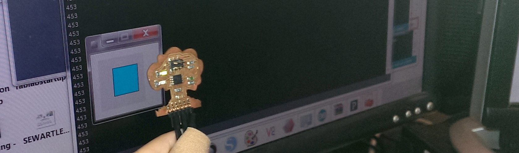
On the electronics side I've started my design. It'll look a lot like my input week with a temperature sensor, but instead of using my output board and driving a motor, a fan is much more simple, I just need to power it so I'll add an NPN to let an ATTiny trigger it, since it needs more like 9V to give a good breeze. I'll keep the LED indicators for troubleshooting and asthetics. I talked a while with Mercedes about it to make sure I had a handle on the where's and the whats and the which pins can be used. If I had a lot more time, I'd make the board look like the honeycomb underneath it and have it snap in and out of place... but that would be tricky because it's produced on the fly by each new set of points from the arm scan. Instead I'll just make it have a similar asthetic with sharp polygons.
UPDATE 7:
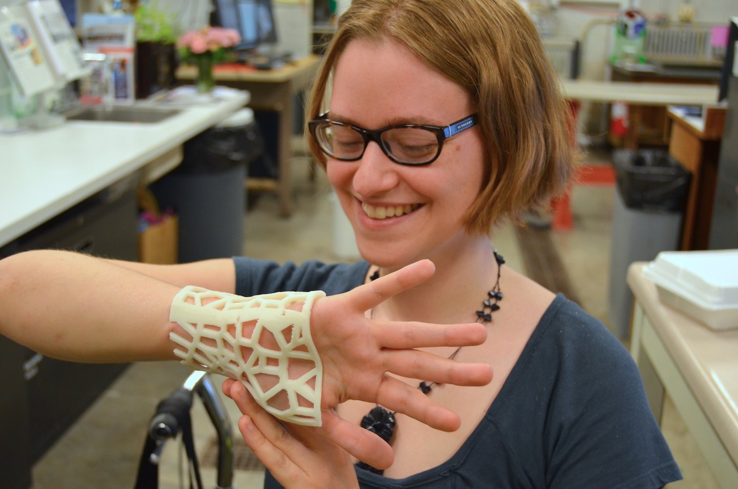
Still working on getting the Voronoi diagrams to work out in Rhino. In the mean time I created a working model in tinkercad that I can ungroup and reimport different wrist brace models from Rhino into. So it's still almost completely parametric/automatic for similarly sized braces... but kind of kludgy! I'm told it's called dirty modeling when you bring point-click modeling into your parametric programs half way through. Which makes sense: it makes the parametric stuff break if you do things wrong/differently than the program was written for so it can be a bit "dirty" in the way it's handled. I have no idea the etymology on that, but that seems as reasonable as any. We'll see if I get the time to finish the Rhino. In the mean time, I have my first 3d printed, neat looking brace. Whoo!
Oh! Also, I hooked up the fan and my old temp sensor tree, and when I put the two together with an npn to turn the 9V on with its ATTiny's 5V logic, all will be well in the world. I have the eagle schematic, but I want the board to look nice and geometric, so I'm still messing with hexagons and other nice shapes to fit it into, and re-styling the ISP headers to be non-standard-ly pointing sideways instead of straight up.
UPDATE 8:
I edited the brace cuts to not have any points that stick out in uncomfortable ways. Second printing went just as well as the first. It works great without any support structure! I just set the UP!s to only print support under base and they graciously didn't print any, hooray.
UPDATE 9:
A couple iterations of an EAGLE file later, the board has blink on it!
UPDATE 10:
Prototype finalized. Updated the Eagle file, even if I didn't cut another board yet. I got the whole thing to work with the fan and a somewhat clunky 9V battery. The fan is much more empressive at cooling than I expected! and the battery... while ugly isn't that heavy that it's uncomfortable. One thing I thought might need some work was in inablility to change the trigger temperature on the fly. It seems silly not to be able to turn it on at will (off is easy-pull out a wire!) or adjust the trigger temp at any time. Maybe a knob, or two buttons, or somthing could be used.
UPDATE 11:
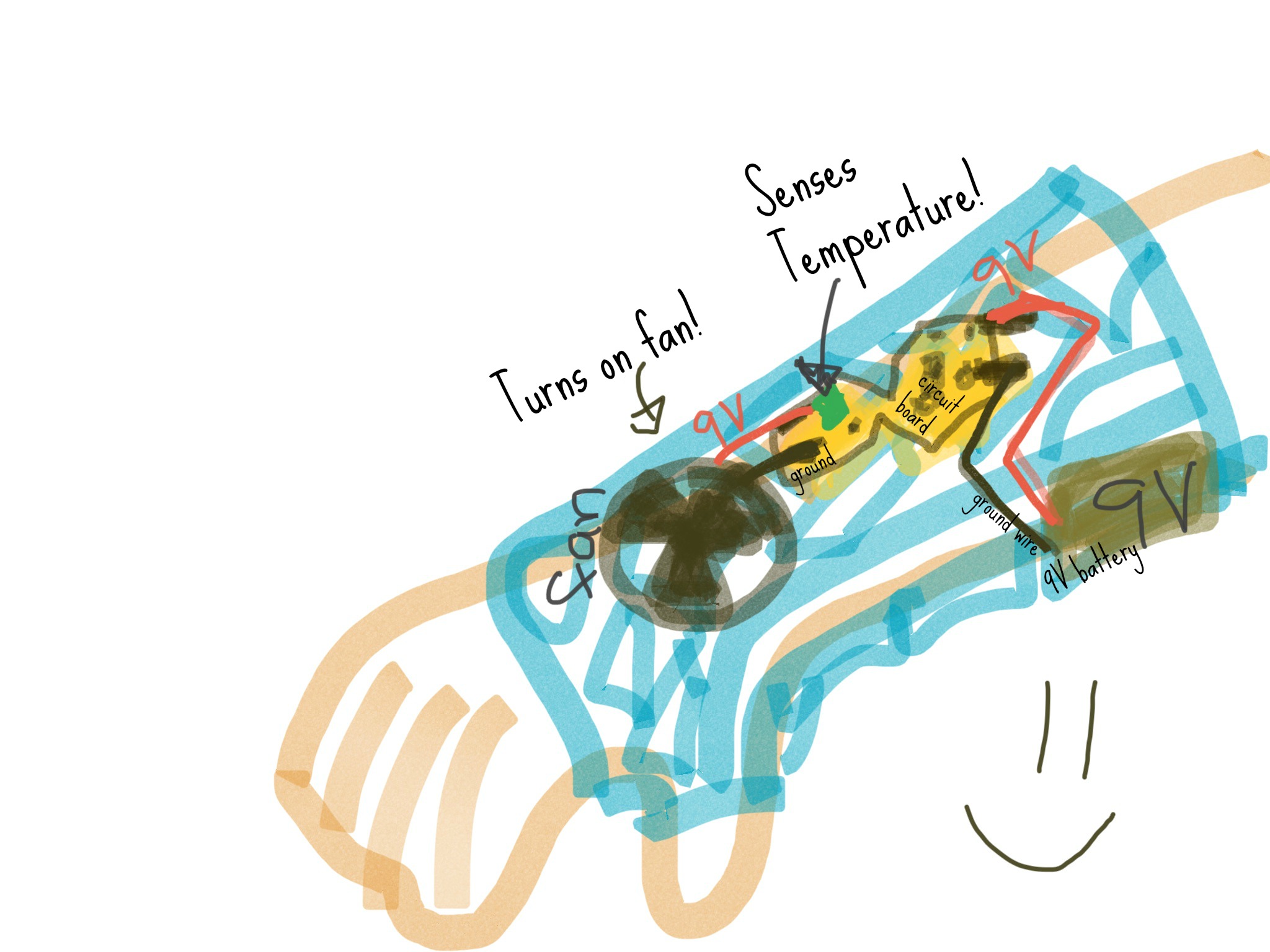
I have a physically moving mechanical object in my design already, but I liked the idea of having a silly looking wiring diagram, even though it's a really simple wiring diagram :) (Fan gets 9V from the 5V ATTINY + npn, and also ground. A 9V battery is attached to the board 9V and ground, providing power to the ATTiny via a 5V regulator and to the fan via an npn transistor. Maybe I should make another cute layout for the board layout...).
How to make your own!
If you want to make your own, follow these steps!
1. Get yourself a scan of your arm/wrist. It may work with knees somewhat, too, but has not been tested. Cut out the background or stray bits that aren't your arm if there are any (NetFabb is a nice free program for doing that) or try and hold your limb such that there aren't any stray bits.
2. Install Rhino (or the generous 90 day free trial of the full version they offer), grasshopper (warning, only for PC, not mac), and the grasshopper plugin weaverbird. Open Rhino. Type grasshopper; in the input at the top of the Rhino window to open grasshopper.
3. In grasshopper File->Open and navigate to open my .gh script. R-click on the first box in the upper left corner in the grasshopper script and select "load geometry" then navigate to the .stl scan file of your wrist.
4. Choose different setting numbers (the yellow boxes) to pick where your brace begins and ends. If you like you can also pick the variables that determine how much buffer around your arm before the brace starts and how thick the brace will be. Those are the other yellow boxes. When you're happy with it, R-click on the final element in grasshopper and select "bake." Whoo! Save the baked geometry in Rhino as an .stl file to 3d print.
5. Edit the brace as you like to look awesome! I recommend any 3d program you like, and if you have never done 3d design before, I love tinkerCAD. Here's an example you can ungroup and use to make yours look similar and awesome.
6. 3d print your file. Now you have a wrist brace that's awesome and perfectly fit to you!
7. if you want to make the electronics parts, refer to the elecronics production tutorial here or elsewhere, and make the board from the eagle plans linked to below. Fair warning, that's a bit more complex.
Downloadables:
EAGLE board and schematic. Program sketch for the ATtiny to trigger the fan with the temperature sensor. Grasshopper script to use in Rhino to produce your own brace from your 3d scan. Tinkercad modeling link for open-plan brace. A bill of materials to make your own. And finally, an example wrist brace that I like that you can 3d print to see for youself. It makes a lovely example print that gets people asking what it's going to be.
This work is licensed under a Creative Commons Attribution-ShareAlike 4.0 International License.