Input
Editing and cutting a new board
Temperature board
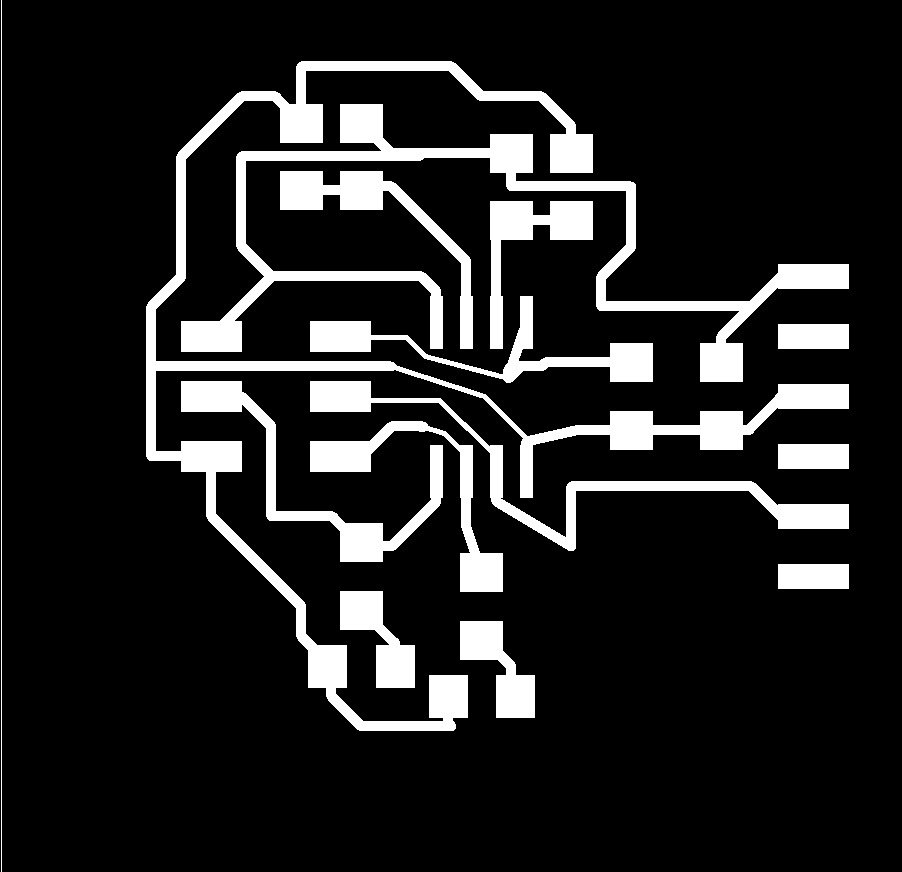
Design the board
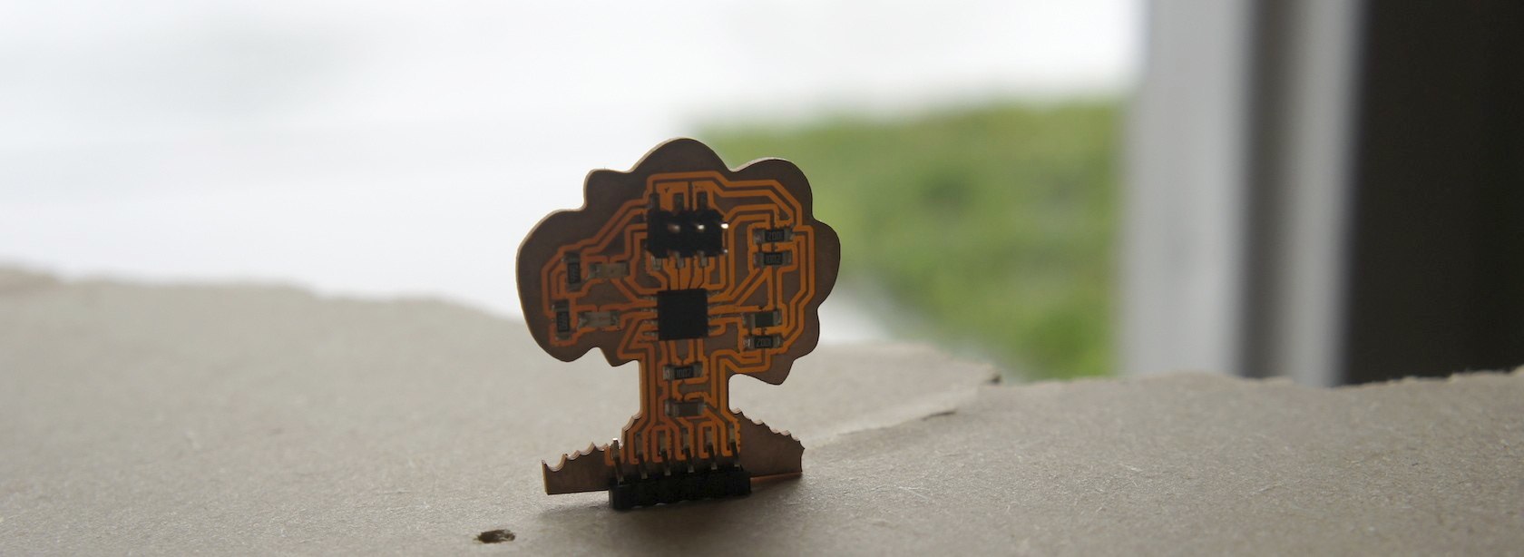
I took the sample board from the archive and added a couple LEDs and resistors as indicator lights, and laid out the board in EAGLE. I've never used a thermistor before (well, by itself), so I looked up how to place it in a circuit. It goes in a voltage divider circuit, just like the example in the archive. It looked a lot like a tree, so I drew a tree and some grass around it in inkscape while it was cutting out the traces on the Modela. I used mostly the defaults in the fab modules. For some reason the modules don't like the images exported from EAGLE, but if you open and resave or reexport them in InkScape, or sometimes Gimp, then it loads them just fine. We were positing that it might have something to do with where it saves information about transparency--in any case it's probably something in the metadata.
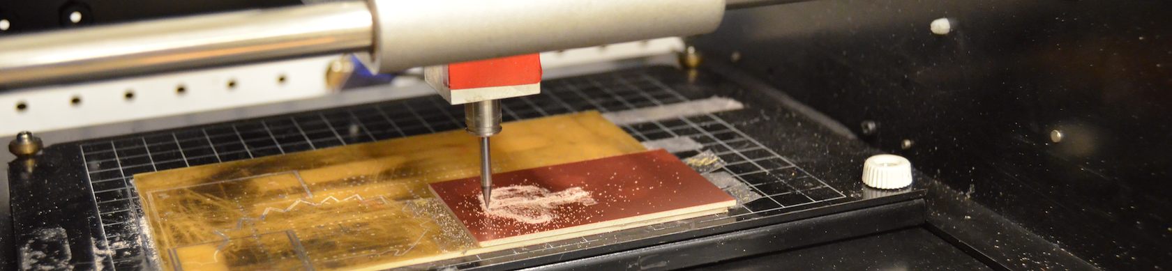
Cut the board out.
Cut the board out on the Modela using the default settings on the fab modules. Type fab in the console on linux. Select png to rml from the drop downs and make it. Import the image file of your traces. White traces on a black background work best. I actually change it from 4 passes to 2 passes around the traces, which I find is plenty and saves a lot of time.

Populate your cut board.
After cutting I wash off the board, to get rid of finger prints, and use a razer or the edge of an uncut board to scrape off any copper shavings that peel slightly without actually coming off. I used a small termistor, the same footprint as a 1206 resistor, to measure temperature. And populated the board with more resistors, LEDs, headers, and a surface mount ATTINY 45. I cut a sticker out of vinyl. Either trace the exported pads in another program or you need to do two things in Silhouette to get a good mask sticker. First, know the size of your picture and resize the imported image to ensure an exact size. Second, push the tolerance all the way down to 4, and get rid of the high pass filter to get squared corners instead of rounded ones on the smaller pads on the mask. Then cut and weed the vinyl like you would any sticker, transfer it to your cut board, then scrape on some solder paste, and carefully remover your sticker mask.

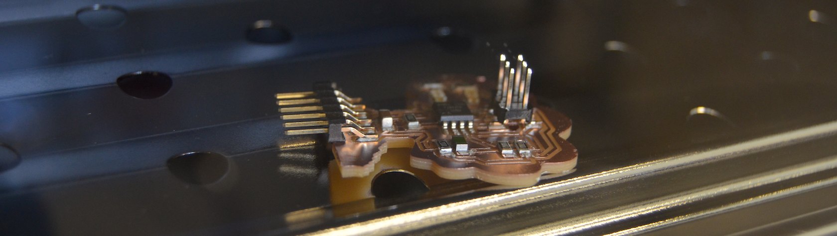
Ready to program
After baking it for a few minutes at 450, then breifly turning it up to 500 till the solder paste melts, it's ready to program
Since I was using a computer, in fact we were using 3 computers that hadn't programed ATTINYs before, I got to remember how to set up the interface a couple times. We were all using the Arduino IDE, and using highlowtech's guide, which is fantastic and straight forward. You add the folder they link to to the Arduino's hardware folder either in the program folder or in the document's folder. Then you can set your board to Attiny, and your processor to 45 with 8MHz internal clock.
The steps I follow from high low tech here, in brief, are: Install arduino (1.6) arduino.cc/
Add support for the attiny on the board
by adding this url to File > Preferences > where to find boards, then using Tools/Board manager to add ATTINY to your list of boards. (link good as of 6/2015)
Or add support by hand.
You can start with example code that changes the thermistor reading to C or F degrees.
But specifically, I started with this library code for thermistors.
I also started with Software serial library. They warn at arduino.cc that it won't work at 1Mhz, but it seems to work anyway?
But you still have to guess, or look up in the Device manager (on windows 7) to figure out which port to select. (EDIT: The new versions of the Arduino software don't make you guess, it identifies which port is what board in the ports menu). Don't forget that you're programing over one port (connected to your fabISP), and when you want to use serial communication after programing, you have to remember to change ports (to your FTDI cable).
So, from the arduino IDE, with your board plugged into the FabISP and that plugged into your computer, with the ATTiny selected as your board, upload your code. After uploading you can check the serial output values with the serial monitor when your arduino is plugged in to the computer through your FTDI cable.
The serial communication gave me a lot of trouble. First, I briefly forgot that you have to use software serial instead of hardware serial communiacation. Then I think I had some port wrong. Who knows. But I finally got it worked out to use pin A3 for my sensor, pin 2 for serial (overloaded from the SCK), and pins 0 and 1 for my indicator lights (overloaded from MISO and MOSI).
It's alive!
It works to communicate the values over serial, and changes those values when someone touches it and warms it up: fluxuating about 10% in under a minute. So I set the threshold to change when the variable crosses the point between room temperature and warmed by a finger. First the blue light is lit, and when warmed they flicker back and forth until only the green light stays on, and the opposite happens when cooling. I'll definitely need to average values to even them out to have a useful feedback loop for my final project, which will need feedback for its cooling circuit.
I also noticed that I had designed the circuit with an extra pair of resistors that go nowhere and take up an extra pin. They might be useful keeping the reading noise low, but it works well enough now. Yay, learning through experimentation!
I was then ready to make a small demo graphically displaying the readings, but I only got as far as installing python and the two dependencies listed for fab lab code on the RI fab archive tutorial for this week and opening up the terminal to start. I wasn't sure if the new version of the pyserial code that they link to would work, so I found someone hosting an archived version with the name they describe. I guess I'll finish writing a gui interface another week. :)
Downloadables:
The key part is the thermister, ntc, which can be found at digikey, part 235-1109-1-ND.
The Fab library, the eagle schematic and board, the traces, the cut for the board, and the pads for the solder mask. And also some code that lights up the green or blue LED depending on how warm the thermistor is.