Output
Editing and cutting a new board
Peltier controller board
(hacking a stepper motor board...?)
Design the board
I looked around for various designs that used atmel chips to control Peltier temperature controllers. (specific keyword: arduino useful in this search) I found a few, but not a ton, and each needed some part that was not in inventory, or just enough different from something that was. Then I checked the fab academy Output boards examples list with Mercedes so that we could see if something might be made to work, thus garanteeing we'd have all the parts in inventory. We settled on a motor shield with 4 npn's a 5V voltage regulator, an attiny44, and a couple resistors/capacitory/headers. This one requires outside power, as well as headers for the ISP (to program it over) and has 6 control pins that attach to the motor (2 for power, two pair for motor control). Just like last time I layed out the board in Eagle with the fab academy libraries. Then exported the image (600dpi, monochrome). Then I imported and exported it from inkscape to avoid whatever problem we have been getting with images exported from eagleCAD.
Cut the board out.
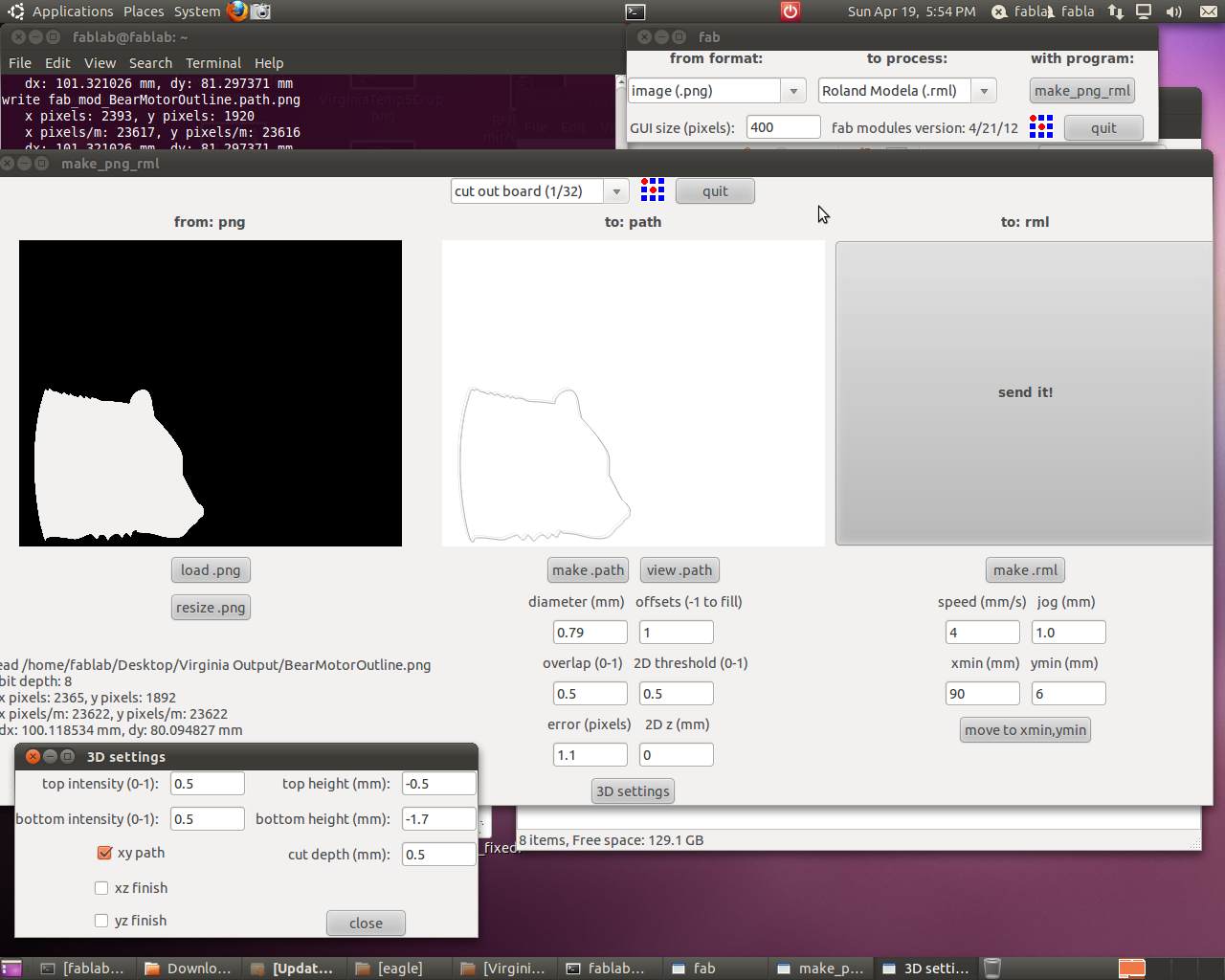
Exactly like previous weeks, cut the board out on the Modela using the default settings on the fab modules. Type fab in the console on linux. Select png to rml from the drop downs and make it. Import the image file of your traces. White traces on a black background work best. I actually change it from 4 passes to 2 passes around the traces, which I find is plenty and saves a lot of time. Before you "make rml" set your xy to the bottom left corner of the board you're cutting and make sure your bit just lightly rests on the surface, and your board is firmly attached to your sacrificial board (I like several stripes of carefully placed double stick tape). I also like cutting out my board in more interesting shapes, because why not? So this time after importing it from inkscape I turned it into a bear. Well, a bear head. Grrrr.
Populate your cut board.
After cutting I wash off the board, to get rid of finger prints, and then use a razer or the edge of an uncut board to scrape off any copper shavings that peel slightly without actually coming off.
I cut a sticker out of vinyl to mask the board for solder paste. Either trace the exported pads in another program or you need to do two things in Silhouette to get a good mask sticker. First, know the size of your picture and resize the imported image to ensure an exact size. Second, push the tolerance all the way down to 4, and get rid of the high pass filter to get squared corners instead of rounded ones on the smaller pads on the mask. Then cut and weed the vinyl like you would any sticker, transfer it to your cut board, then scrape on some solder paste, and carefully remover your sticker mask.
Ready to program
After baking it for a few minutes, preheated to 450, then breifly turning it up to 500 till the solder paste melts, it's ready to program. Take it out immediately after all the pads turn shiny, which should be just before 500. Remove from hot metal tray and let cool.
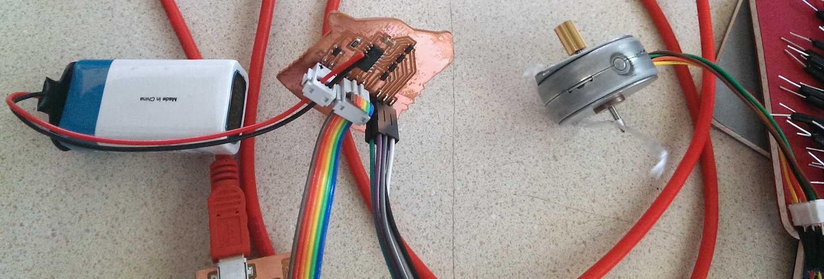
I hooked up a 9V battery to the four pins for power, the fabISP to the ISP, and the stepper motor to the last six, using the circuit diagram to match the pins. The motor turned on, stepped as instructed and moved quite happily at different speeds and different steps according to the program (set in arduino using the highlowtech hardware libraries for the ATTINY). The pins turn on and off in sequence to continue to drive the motor in a circular motion, but they use transistors (4 npn transistors) and 9V power. The same 9V power also powers the board using a 5V regulator so as not to burn out the chip. Note the motor pins are denoted in the software as pins 0, 1, 2, and 3, but attached to hardware pins 10-13.
It was really unfortunate the Peltier cooling/heating device did not have nearly such good success. It did heat and cool probably, very slightly. But I could not get it to cool noticably unless I detached it and attached it directly to the 9V battery. I tried both pwm signals, and a straight "high" signal. The only thing that happened is that occasionally the ATTINY would get hugely hot.
It's alive!
So the motor shield without question worked as a motor shield, but didn't work quite so well to drive a Peltier device. So, while I successfully made a stepper motor board, I did not successfully hack it to cool.
Downloadables:
The Fab library, the eagle schematic and board, the traces, the cut outline for the board, and the pads for the solder mask and the vector file for the layout. And then here's the code that steps the motor.