W_19: Project development (Jun 3)
CONCEPT
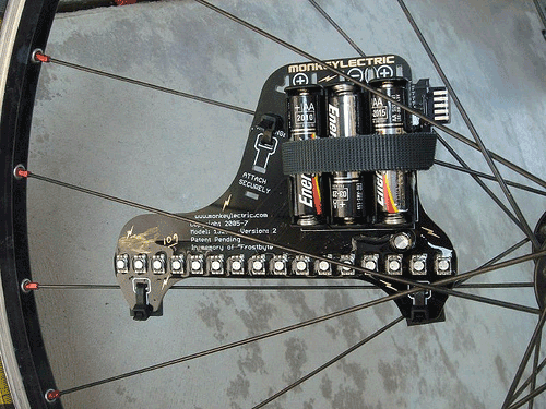
The Basic concept of my final project is to make a bike light that attaches to your wheel. Simply an RGB led strip that turns on your wheel while your riding and changes colors and blink rate according to your velocity.
The idea is to join a long led strip to a circuit board that is programmable with a magnetic switch that reeds the velocity that your at and changes the state of your led strip.
Here is a basic idea of what I'm trying to achieve:
WHERE TO START?
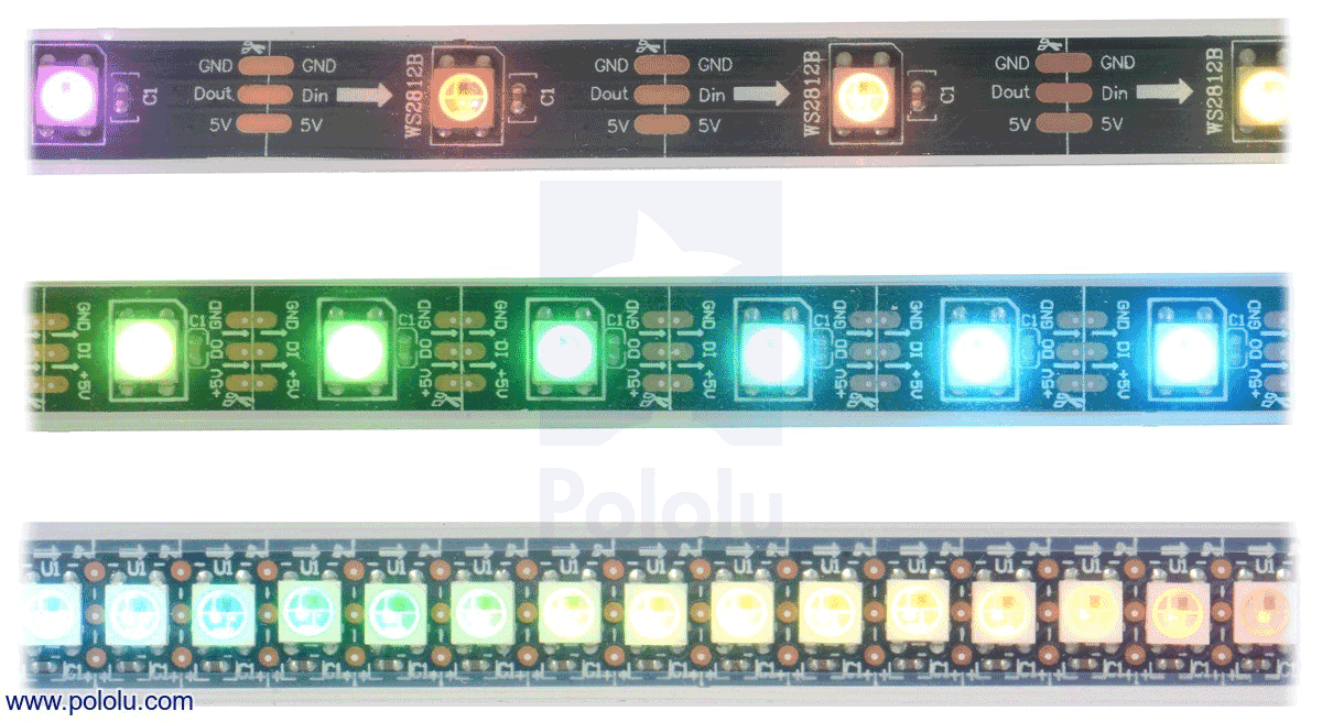
I needed to start of somwhere so I investigated previous projects of the same field and it made its self clear that it was a complicated system to construct. It involved a programmable circuit board that could act as an intermidiary between an led strip and a computer. I started of with the idea I could use an arduino board because it was an easy interface to use and play around with. We had a role of WS2812B in our lab so I decided to use this for my final project.
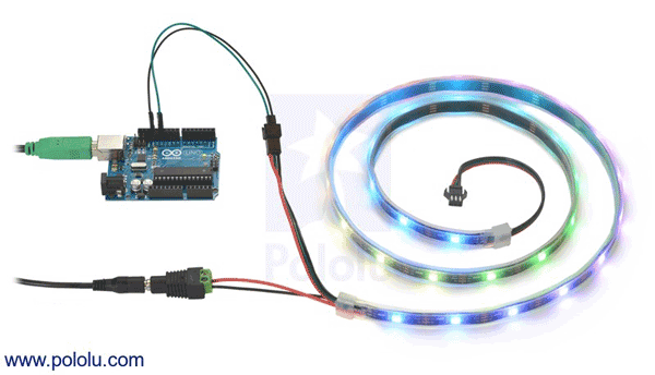
I researched the name of this on the internet and on the web page they sell it at they have a library to program the arduino board called Polulu and later on I looked for others and eventually found another library called Adafruit called NeoPixel. Here is a little test i made with the comercial arduino uno and the standard test of the neopixel library:
WHERE TO FOLLOW?
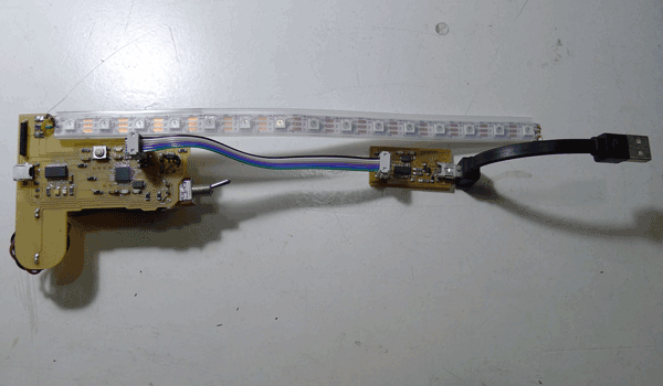
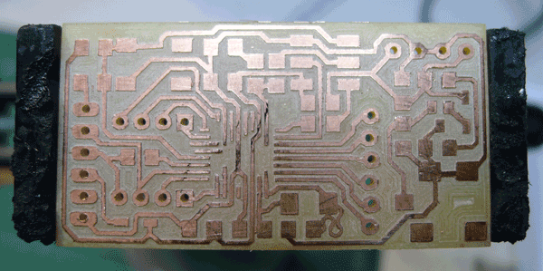
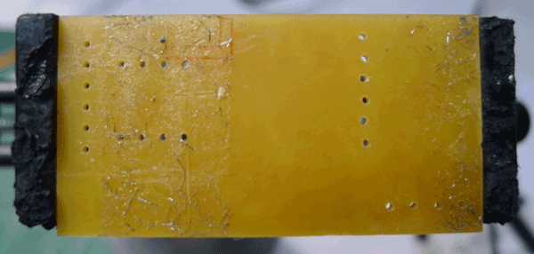
When i had played with the arduino libraries enough i started thought I could make my own arduino board to test the led WS2812B strip so i asked Ferdi(my instructor) if there was any fabable arduino boards and he pointed me to the BARDUINO where i found intructions on how to make the board and all the components needed. I made the barduino pcb board with the Roland SRM-20 in the lab.
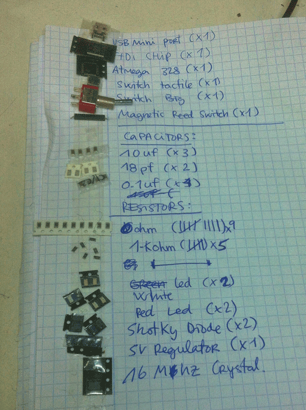
Here is my milled pcb barduino and its components:
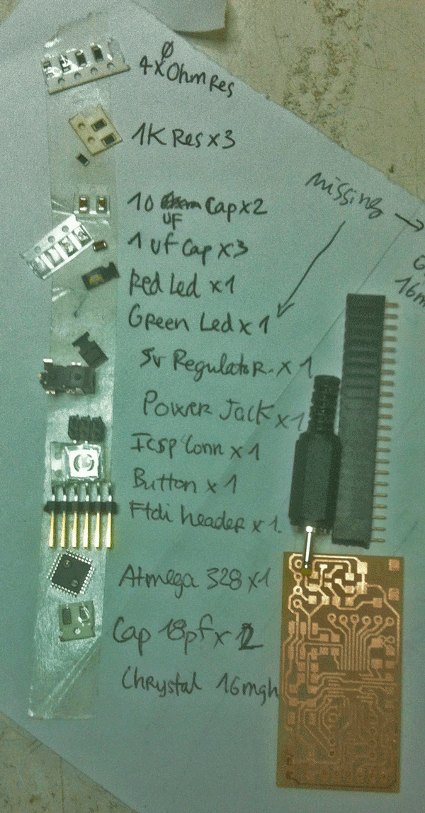
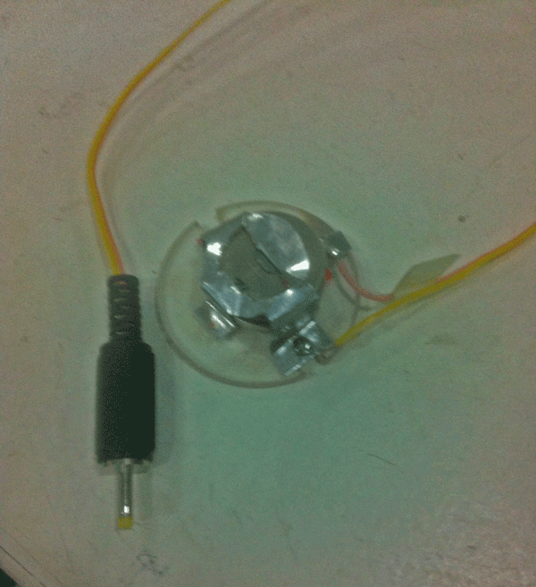
After stuffing all the components on the board I burnt the bootloader on Arduino ide and made it blink to test if it was working properly. Once this was done i hooked up the barduino to a power supply i made out of a cocacola can and plastic.
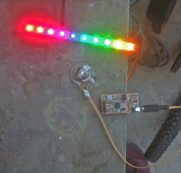
When this was up and working and plugged in the arduino I plugged the led strip into my board.There are three connections on the led strip: one cable goes to ground, the other to 5v and the last one goes to a pin for controlling it. This is what it looked after programming the arduino to a specific pin to control the led strip with the polulu library in arduino.
WHAT NEXT?
When i had the general idea of what my project was going to be comprised of i wanted to design my own board wich would contain:
· BARDUINO COMPOENTS(without the female pin headers, simply the holes)
· FTDI CHIP (to control via usb cable instead of the ftdi cable)
· Magnetic reed switch(that reeds 1 and 0's to control the frame rate of the leds)
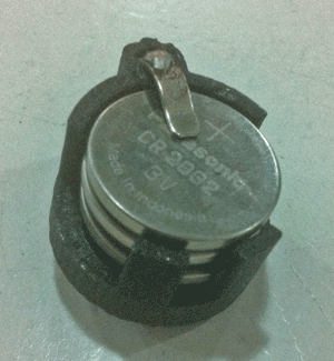
· BUTTON BATTERY HOLDER(that houses 3 lithium flat batteries in one single case)
· WS2812B LED STRIP(with about 16 leds on it)
· SWITCH(to turn on and of the power to the board)
DESIGNING THE BOARD
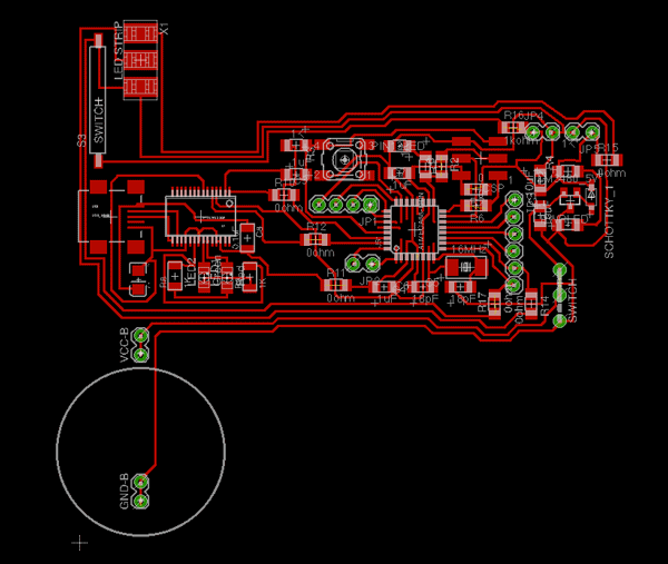
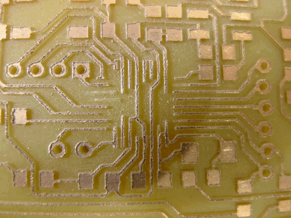
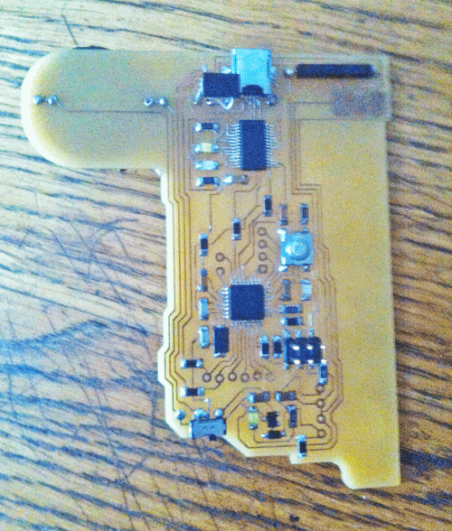
This is the design of the first board I made:
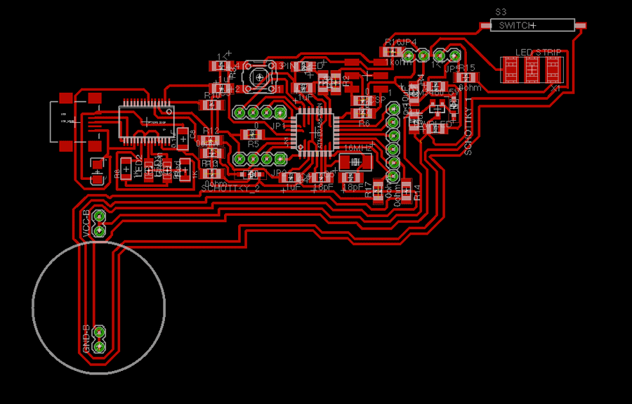
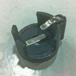
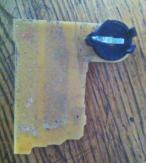
The circle you can see on the image is the size of the button battery holder printed in 3d. First i redesigned a file i found on thingiverse in rhino and printed it later on and added conductive metal to make contact with the batteries.
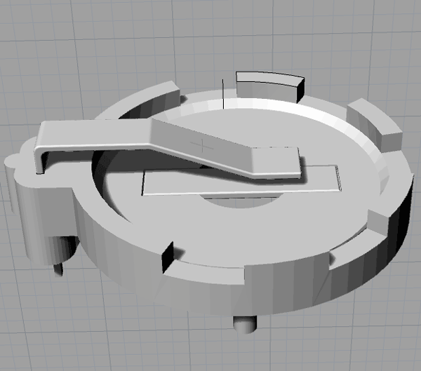
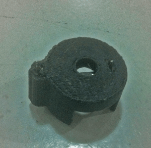
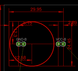 The last image is a diagram to the distance between the pins that come from the battery holder.
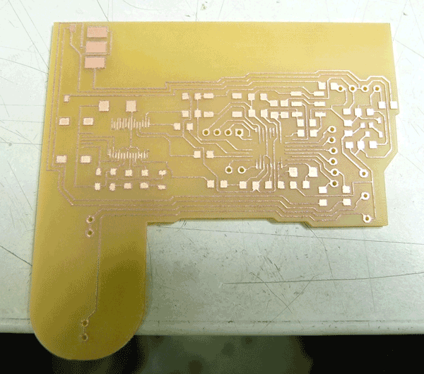
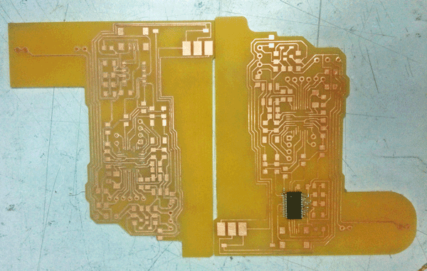
After a closer look at this first board design i saw there where to many connections and the placemnt of the led strip pads was not going to work for what i wanted so i redisigned the board again so it would work propperley. Here is the second design.
To mill the boards I used 3 different mill bits:
1. The 1/64 inch for taking away the majority of the copper
2. The 0.10 inch mill bit to get through the smallest traces 3. Finally the 1/32 inch mill bit to cut the board and make the wholes
I had to mill the board 3 times because for some reason the mill bit was not going through some of the copper traces or it was eating the copper traces away. Finally i figgured out the problem wich lied inside the rml files. The cut depth was too deep. Also the 0.1 inch mill was broken and it made burs on the copper.
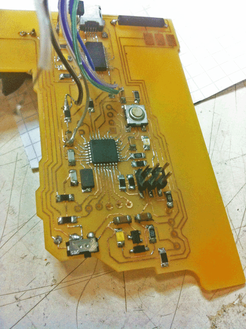
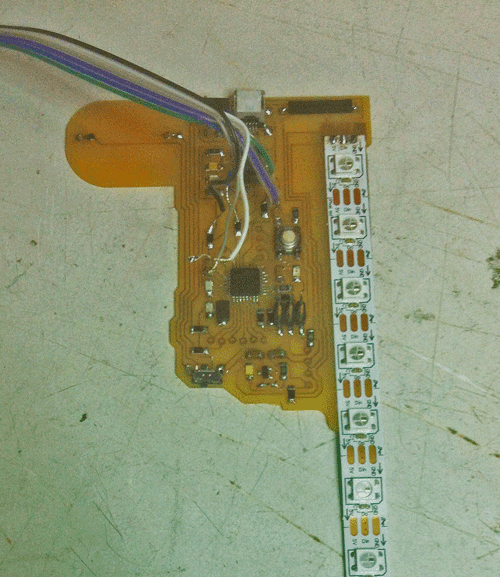
I cleaned the board that had the best result and started stuffing it.
When plugging in the board to the computer with the usb cable my computer warned me that the board was consuming to much power from the usb port and in the arduino program the board didint appear as recognised there was some problems with the ftdi chip of the board and it was crashing my computer so i decided to solder cables directly from the barduino part to an ftdi header. I managed to make it work for a short period but then it stopped working again.
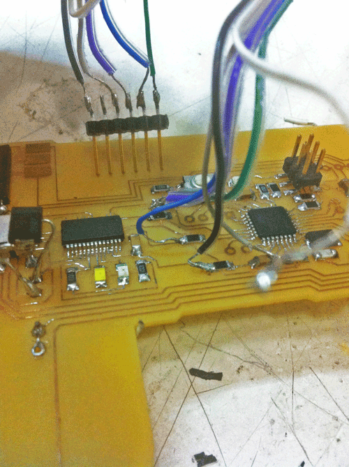
I realised that the problem relied in the power so I changed the battery holder to a 9v battery holder that I glued on the back of the pcb board and changed the voltage regulator to a 5v 1.0 Amperes. When trying to program the board on arduino the magnetic reed switch wasn't working either i tried various times changing the code still no result. It wasn't reading the magnet when i passed it over the switch so i decided to stop concentrating on that part of the idea of using the magnetic switch and simply programming the board with the different codes provided by the neopixel library as the standard test to at least make it work in some sense.
As the connection to usb doesnt work i found a way to load the program into the board through the fabisp pressing shift while loading the programing in arduino ide so this way i solved the problem of it not beeing able to load anything.