W_14: Networking and communications (Apr 29)
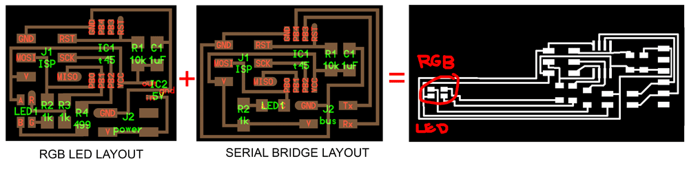
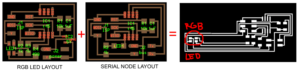
This weeks assignment was to design and build a wired or wirless network two or more processors. The way I approched it was designing the simple serial connected board but exchanging the normal led for a rgb led. I fused the rgb board with the serial board and the same with the node board.
Designing and making the boards
Here is the schematics design of the bridge board:
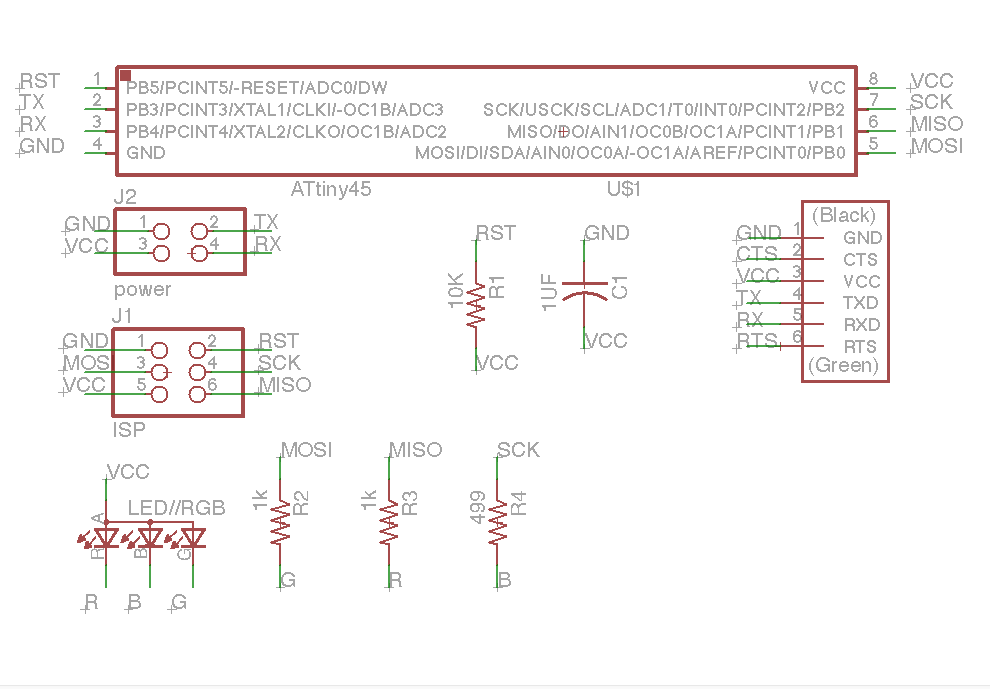
The only thing that changes between the bridge layout and the node layout is that in the bridge layout the rx and the tx run thrue the the ftdi header connections and in the node they run directly to the power source.
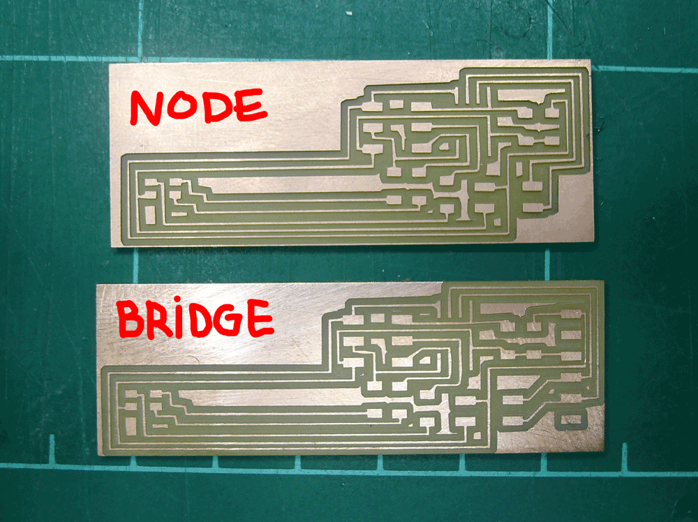
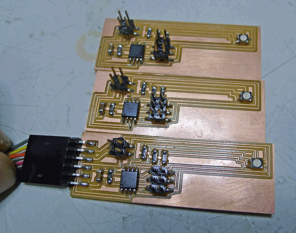
I milled and stuffed one bridge and two nodes tohave a network of three processors instead of two. Here is a photo of the two kinds of boards:
After stuffing the three boards this is how they came out:
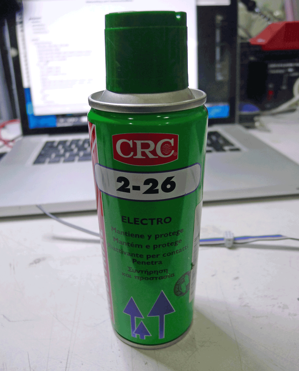
I put on a protective layer this time because i noticed that my boards where getting corroded over time. Iused a sealing agent that protects the boards from the enviorment:
Programing the different boards
For programming the different boards I was going to combine both the rgb C file and the bridge/node files but was uncuccesfull and was running out of time for the assignment so decided to just stick to the C file given to us for the serial boards acting on the led as if it where a normal one coloured led.To program your boards it is done in these simple steps:
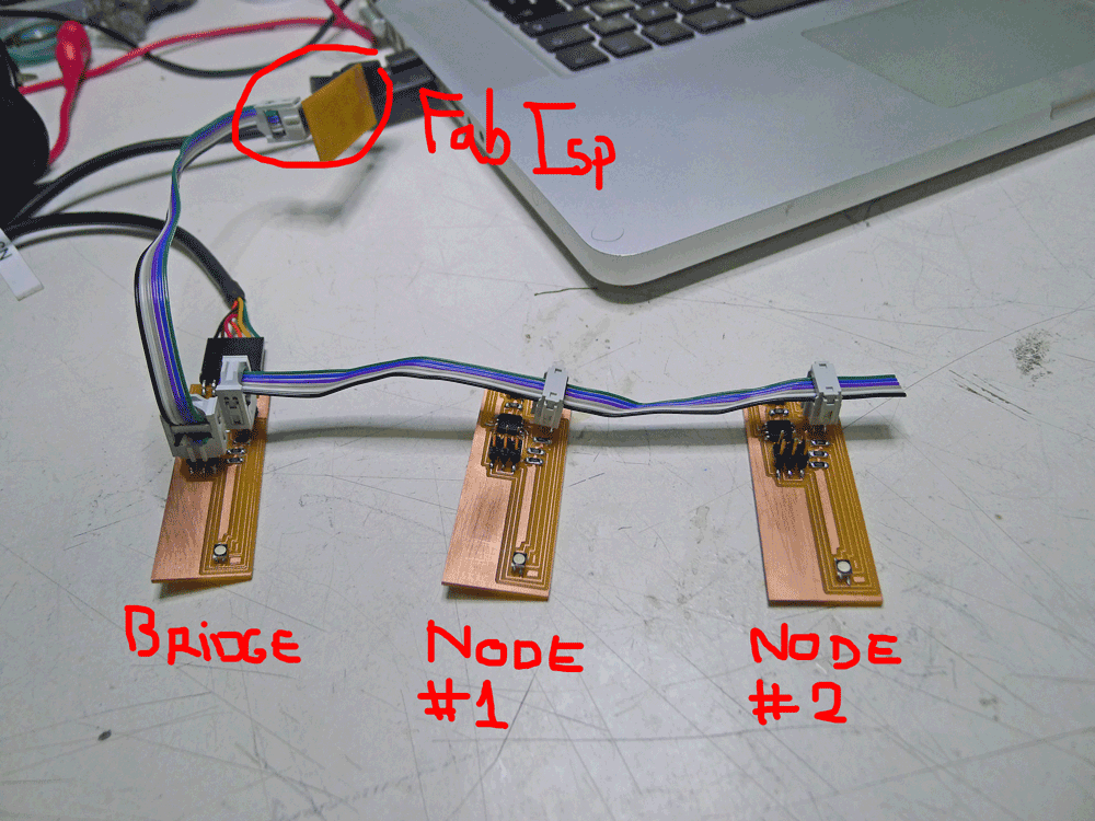
1· Connect your fabIsp from week 4 to a usb port.
2· Connect the fabIsp to your first board(bridge) through the smd 2x3 connector and a serial cable connection on both the fabisp and the bridge(as you can see in the image).
3· Make a folder contaning the make files an the the cad files together.
4· Open your terminal and change your directory to where ever you made the containing folder.
5· When all of this is connected propperley you should type in the next command(make -f hello.bus.45.make program-usbtiny). If everything is correct your board will turn on the led while its loading the file in to the attiny45 and no error message should appear. The name in the C file of this board is node '0'.
6· To program the node(not the bridge) you need to change the node '0' to node '1' and save the file. Right after you should repeat the process but this time connect your fabisp to the node(not the bridge board) and repeat the command line in terminal, you will see now that your second board turns on the led while loading the file in the attiny45. Repeat this with all the boards you may have.
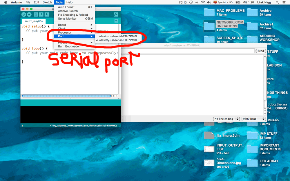
7· Next step is to check if the network you created is working according to the code inside of them. I used Arduino program on my computer to to this but u can use any program that is more comfortable to you.
8· When in the arduino program you have to select the port you are using and open the serial monitor.
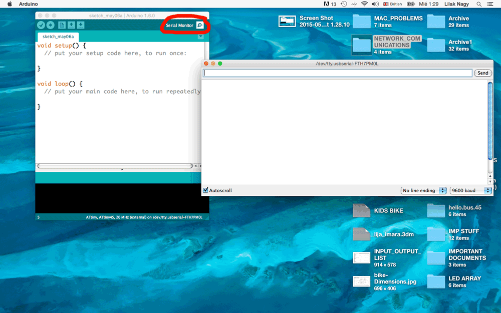
9· When in the serial monitor if you type 1 or 0 and enter all the led's will flash once, if you press 2 and enter the node '2' will blink twice.
Final Observations and comments
I havent figured out how to change the code to my liking so i can tweak all the delays between the led and make it chandge between red green and blu but as i was running out of time i had to end it here, I will continue playing and merging codes and tray to make it possible to make the lds change to my preference but untill now this is what i have so far.FILES
· BRIDGE SHCHEMATICS
· BRIDGE BOARD LAYOUT
· NODE SHCHEMATICS
· NODE BOARD LAYOUT
· BRIDGE BOARD LAYOUT
· NODE SHCHEMATICS
· NODE BOARD LAYOUT