W_08: Computer-controlled machining (Mar 18)
This weeks assignment was to create something big. To make this possible we all used a wooden board, in my case an osb board (2250x1225mm). First of all was thinking of what big thing to make, I started thinking about making some kind of bike frame for the final project but that was not going to be possible with the material we had it has very pour structural properties for that kind of objects. I started shaping a diferent idea around the assignment so it became a making of a chair. I wanted to make a personal workspace chair where you would be able to sit and have desk space.
1· SKETCHING THE CHAIR/WORKSPACE
First of all started scetching a couple of ideas to concieve what it was going to look like and how it was going to purpose the person using it.
Here are my inicial sketches:
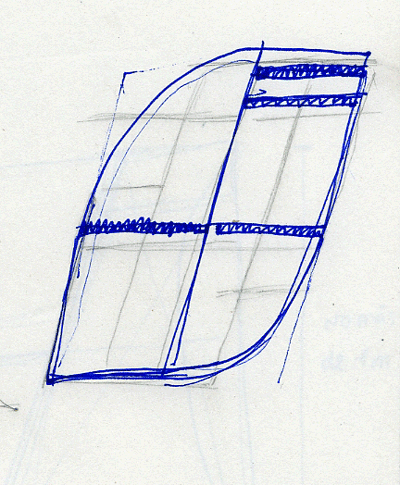
These are a pair of side views of a possible chair shape
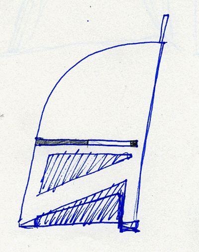
This is more closer idea of the final idea for the chair where i was figuring out the angles of the parts and the way they would interact between echother.
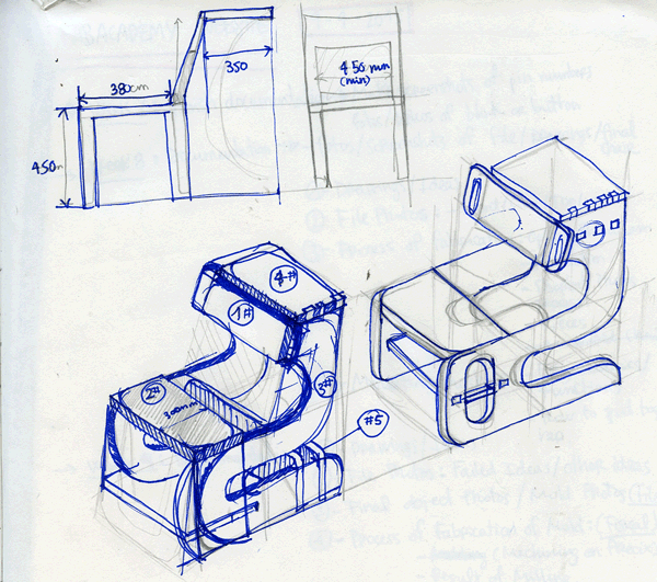
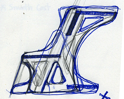
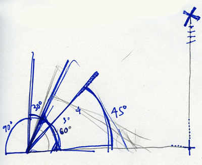
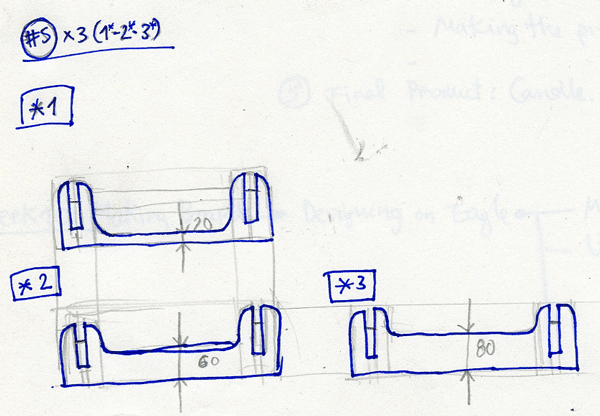 Finally after some better thinking this is the idea I developed to create. As you can see in the drawings we can see the basic measurments decided to work with and the for the distribution of the different elements. After this i started designing all of the parts directly on rhino from 2d lines that later on where extruded.
2· DESIGNING THE CHAIR/WORKSPACE ON RHINOCEROS
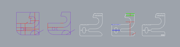
After this i went ditrectly to rhino to start designing the actual parts of the chair. You can see in the next image a progress of the most essencial part wich gives the shape of the chair on its side.
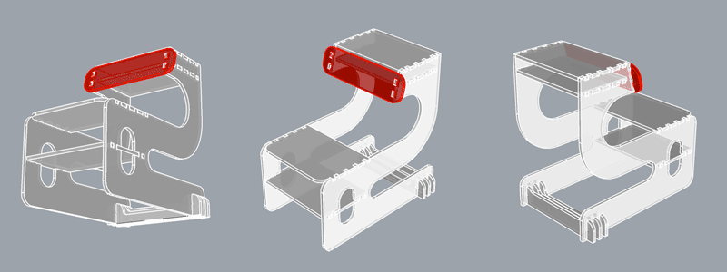
When i finished designing the chair on rhino i took some screenshots in perspective:
3· SETTING THE RHINOCAM
For me to be able to cut the chair pieces out i had to pan the design on to a 2D plane and later on select these for rhinocam (plugin for rhino that allows you to calculate cutting paths and generates a file for you) to later cut it on the shopbot. Here is the front view of the organization of the cut file: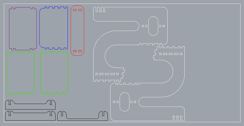 The exterior white rectangle is the size of the wood I used(OSB 2250x1250mm).
After this its time to set the rhino cam settings:
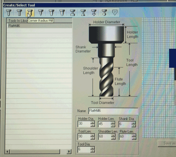
1· Set the mill bit parameters to the ones of wich you are going to use. I used a flat end mill of 6 mm.
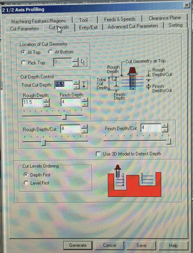
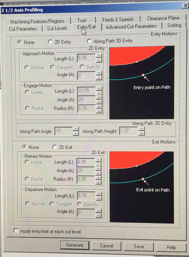
2· Once we have the size of the tool its time to set the cut settings, wich involves: cut levels, entry and exit, feeds and speeds, sorting(cut directions) and finally tabs(to secure the pieces from moving).
CUT LEVELS(the levels the mill bit will be going into the wood)
ENTRY AND EXIT(the path of the tool when starting to mill)
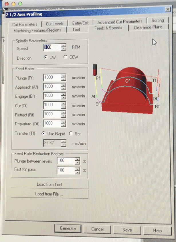
FEEDS AND SPEEDS(velocity of the tool and tool head while cutting)
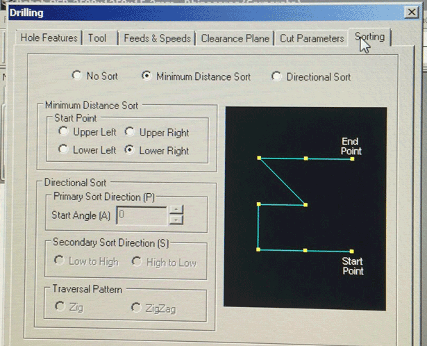
SORTING(Cut directionalityin reference to the material/file)
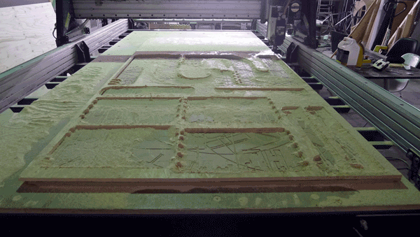
4· CUTTING ON THE SHOPBOT
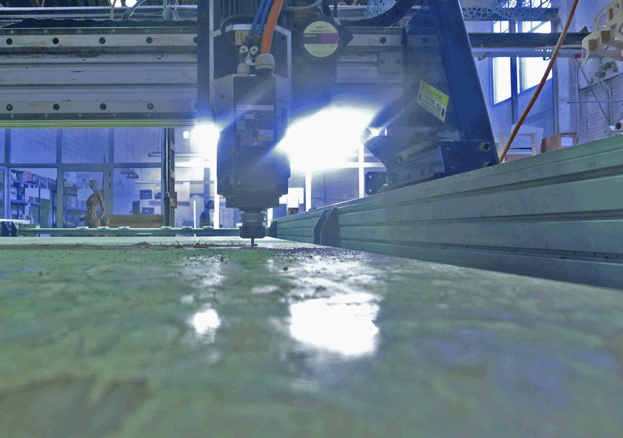
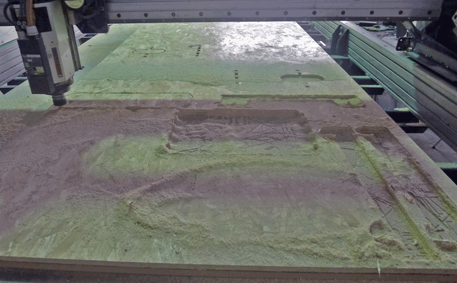
To cut this it was necesary to generate a gcode for the machine to understand in numbers and coordinates to cut as you have designed the rhino cut file. I exported two different gcodes: First the interior holes and after this the exterior profiles. All the pieces had tabs on them so when they where almost done cutting the pieces wouldn't move and get spit out by the spindle. Here are some photographs of the process of fabrication:
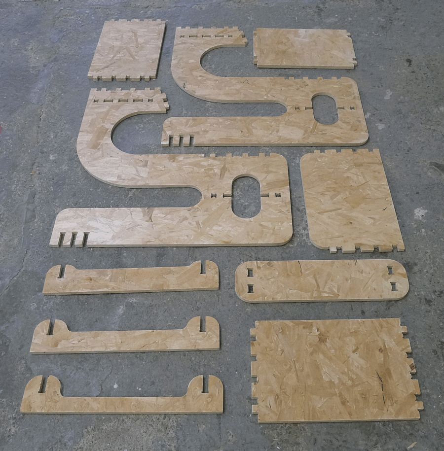
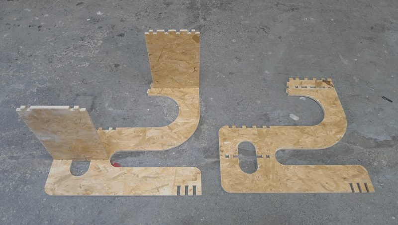
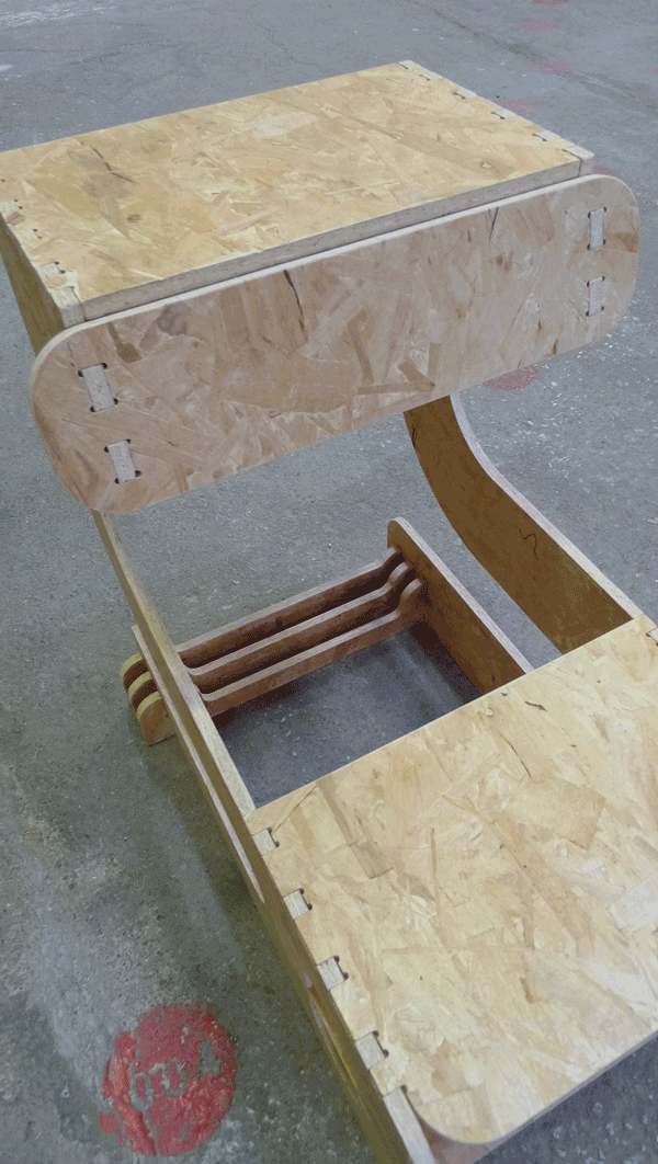
After sanding here are the finished pieces. I also made a couple of photos of the mounting process:
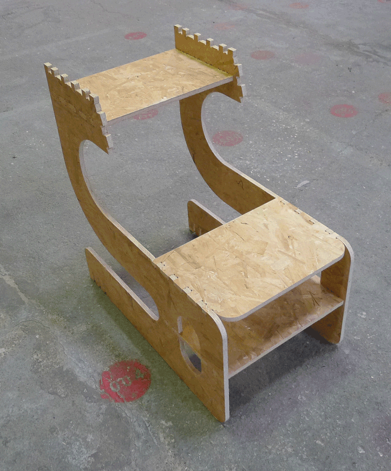
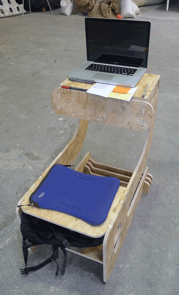
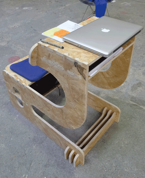
Finaly I filled the chair with objects to show posible aplications:

FILES
· INITIAL SKETCH RHINO FILE
· FINAL RHINO CAM FILE
· SHOPBOT GCODE CUT FILES
· FINAL RHINO CAM FILE
· SHOPBOT GCODE CUT FILES