About Week 8
My Computer-Controlled Machine Exercise...
This week assignment is about Computer-Controlled Machine: design and make something big.
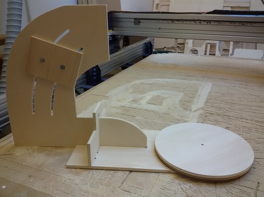
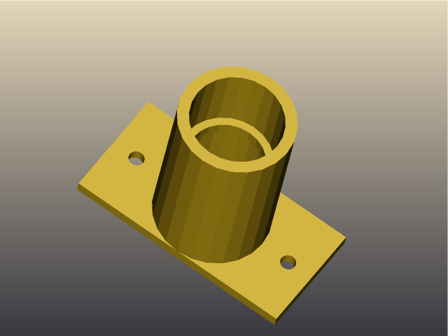
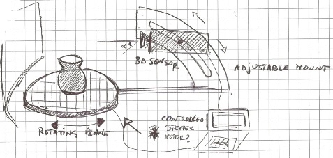
For my exercise I decided to make an idea from my previous exercise: 3d scanner mount. The system should enable to fix, with a variable angle and height, a camera, a 3dscanner or a Kinect. The rotating system should be composed of two circle surfaces divided by a smaller one, in order to rotate a surface respect the other one by means of several spherical wheels. The rotating plane will be moved by a stepper motor.
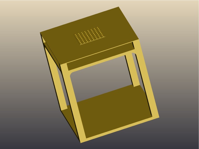
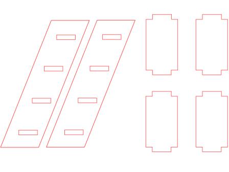
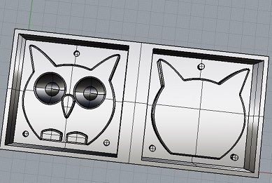
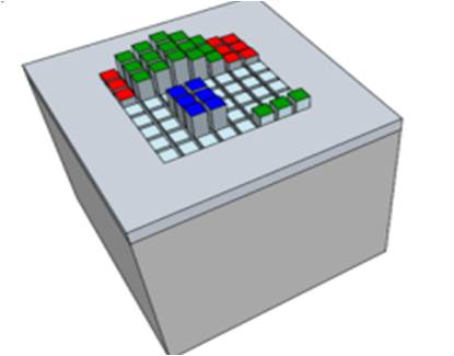
First of all I designed with Rhino the components of the stand, taking into account that I will assembly them only by joints and I will use a 12 mm wood sheet
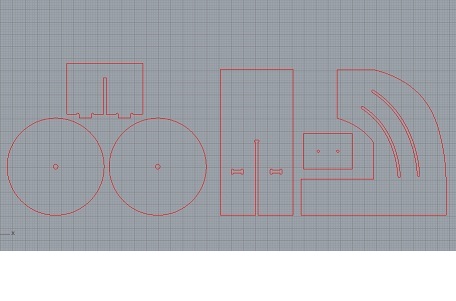
After the design of 3d model I realized that some minor correction are needed: the junction piece between horizontal and vertical planes had to be reduced and a need of smaller round plane between the bigger ones:
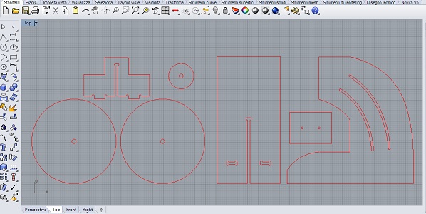
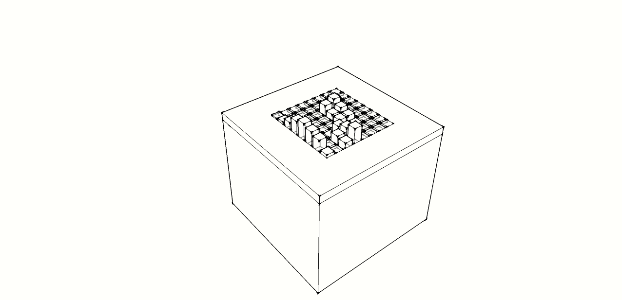
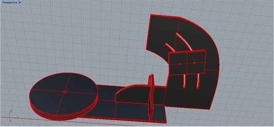
Again the design of the 3d model to verify other issues
Download the stl file
Download the Rhino file
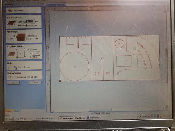
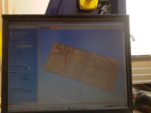
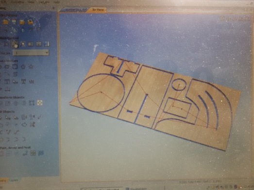
I exported the Rhino design file in a .dxf one to be imported in vCarve Pro in order to configure the ShopBot CNC Machine and produce the GCode files, that is in a format suitable to be read by ShopBot CNC controlling software
The production of GCode file is the result of several low level configuration in vCarve. A first step is the optimization of the cut by using Nest Parts feature. In my case the design was already optimized.
Next step was to select all internal cuts for a first cut in order to avoid possible movement of the the wood sheet. And then the configuration of external ones. This process produced two different GCode files to be executed sequentially.
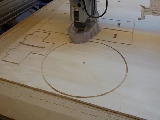
during the second step, an inconvenience occurred. The 6mm CNC bit has moved internally to the spindle that caused a not perfect cut. I stopped immediately the machine without shutting it down, in order to recovery the cut process. I adjusted the bit and I setted only the z axis.
From a first check some cuts are not good maybe due for the machine stop. Fortunately they were only two cuts that I smoothed quickly.
Before starting cuts, I used the ShobBot controlling software to reset X and Y axis, once placed the machine in a suitable x,y position, and finally to calibrate Z axis by using an ad hoc metal plate connected with an electrical wire to the ShopBot machine.
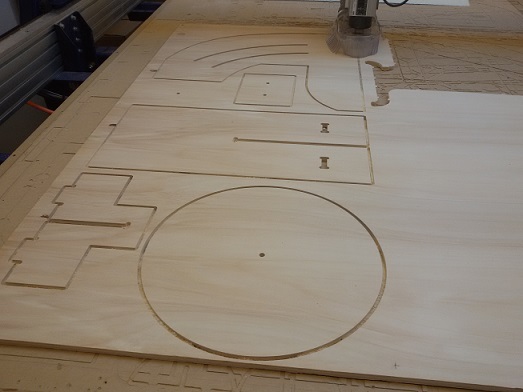
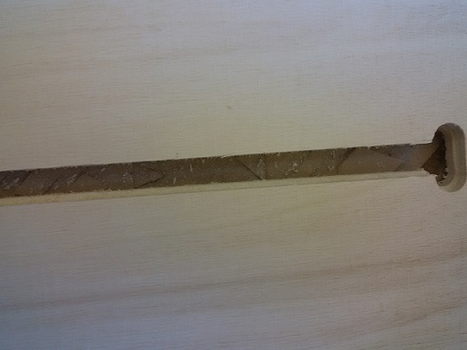
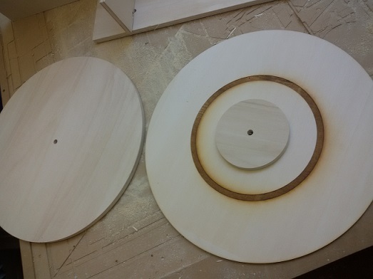
Here the final results: one of the round plate has been engraved by the laser cutting for the guide of spherical wheels