Electronics design תכנון מעגל אלקטרוני
This week's assignment was to design an electric board, we had to add to the hello echo board atleast one led and a button.
this week i used Anna's tutorial all the way threw
I started by using Eagle software  this softwre helps editing and designing simultaneously the board.
the first thing was to open a new shematic and add components:
Resistor ( 10k Ω )
Resistor (499 Ω)
Button
Led
VCC (power) and GND (ground)
המשימה השבוע היית לתכנן ולעצב מעגל אלקטרוני, לקחנו את הלוח "הלו-אקו" והמטרה הייתה להוסיף לו לפחות לד אחד וכפתור.
השבוע השתמשתי לאורך כל הדרך ב
טוטוריאל של אנה
השתמשתי בתוכנת איגל  התוכנה עוזרת לערוך ולעצב את הלוח בו זמנית.
הדבר הראשון היה להוסיף רכיבים לסכמת הלוח
נגד- 10 קילו אוהם
נגד- 499 אוהם
לד
כפתור
אדמה וכניסת כח

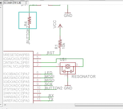
Once i finished adding components i connected them to each other, not randomly (!), each component goes to its place, if you want to connect a component's leg to a different component's leg, you can connect a wire between them, or extend the leg with the wire, name the extended leg and do the same to the other leg, if both legs have the same name, they connected.
after connecting all the components, i started editing the wires on the board.
לאחר שסיימתי להוסיף רכיבים, התחלתי לחבר אותם אחד לשני, לא באופן אקראי, כל רכיב מתחבר לרגל המתאימה או לרכיב המתאים. אם אני רוצה לחבר בין 2 רכיבים, אני יכולה למתוח ביניהם קו מחבר או להאריך רגל ולתת להארכה שם. את אותו השם לתת לתת לרגל אליה מתחברים וכך רגליים בעלות אותו השם, מחוברות.
לאחר שסיימתי לחבר בין הרכיבים, התחלתי לערוך את הקווים המוליכים המחברים בין הרכיבים.
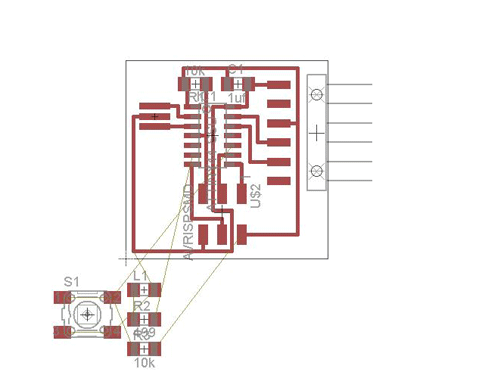
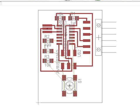
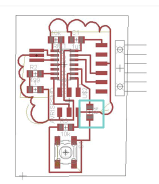
because i tried to design my board like a tree (was't that successul), i came across a problem, one of the wires had to go threw another wire. מכיוון שניסיתי לעצב את הלמעגל כדי שיראה כמו עץ (לא יצא מוצלח במיוחד) נתקלתי בבעיה, אחד הקווים המוליכים היה חייב לעבור דרך קו אחר.
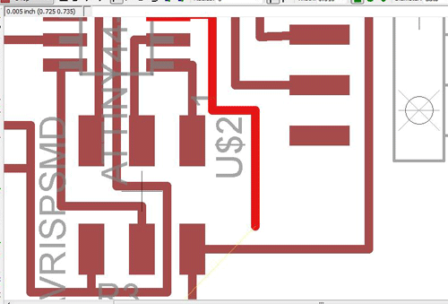
to solve this, i added to the schematic a resistor with the value of 0Ω, this resistor serves me only as a bridge. this way one of the wires can "jump" on top of the other, and both of which won't touch each other. כדי לפתור את הבעיה הוספתי בסכמה נגד שערכו 0 אוהם. הנגד הזה משמש כגשר, כך קו אחד יכול לדלג מעל הקו השני בלי שיגעו אחד בשני.
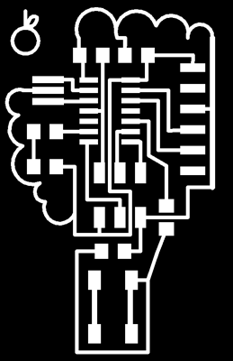
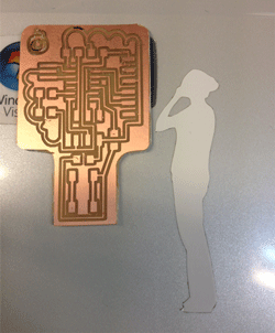
after i finished editing and designing the board, i saved it as png image. the background is black and the wires and components pads are white. the white is whats left on the board, after milling. לאחר שסיימתי לערוך ולעצב את המעדל, שמרתי את השרטוט כפי.אן.ג'י. כאשר הרקע שחור והקווים והפדים של הרכיבים בלבן, מה שמסומן בלבן, זה מה שנשאר על הלוח לאחר הכרסום.
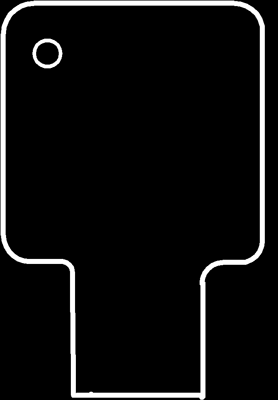
in order of sending the board for milling, i needed to create lines to cut out the board (interior), i first tried using adobe illustrator, but the lines became thiner and as a result the milling wasn't good.
i decided to create the traces with eagle, drew it like the wires, and saved it as png
כדי לשלוח את המעגל לכרסום עליי לייצר את קווי המתאר של הלוח כדי שהכרסומת תוכל לכרסם אותו החוצה. ניסיתי לעשות זאת בעזרת אילוסטרייטור, אך ללא הצלחה, הקווים המוליכים הגיעו דקים יותר ממה שהיו והמעגל כורסם בצורה לא טובה.
החלטתי ליצור את הקו החיצוני בעזרת האיגל, השתמשתי בקווים המוליכים ויצאתי קובץ פי.אן.ג'י.
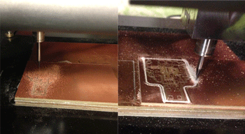
to mill the board, i uploaded the png image to fabmodules and chose from png to rml. as i explained on week 4 , then i chose the bit for milling and created the path for milling. i did the same with the file for cutting out the board. כדי לכרסם את המעגלת העליתי את התמונה לפאבמודולס ובחרתי מפי.אן.ג'י. לאר.אם.אל. כמו שהסברתי שבוע 4
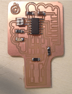

You can see the programming of this board on week 8 אפשר לראות את התכנות של המעגל ב שבוע 8
