Caution! José Figueroa at FabAcademy 2013
Weekly report of my work at FabLab Barcelona
For this week's homework we had to make our boards do something in different programming environments. I set out to do something simple using the Arduino IDE and C language. My goal was to make the LED of my board to light with a low intensity for one second and high intensity for another second. This would be interrupted from the push-button.
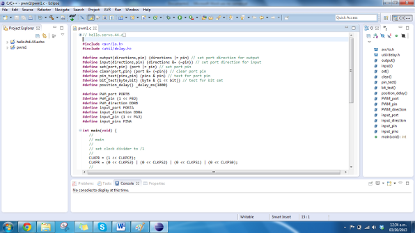
First thing to do: download the necessary software and drivers. The Arduino IDE can be downloaded from the official Arduino website. I decided to work in Windows 7, 64 bit, so I had to download the drivers for the FabISP for Windows. Using this a tutorial, I found the links for the drivers I needed. I also downloaded WinAVR, which is a software toolbox containing the necessary libraries to program AVR microcontrollers. To program in C, I decided to use Eclipse becuase I had experience using this IDE before when programming with Java. I followed this tutorial to set up Eclipse to communicate with AVR microcontrollers.
After I set up the necessary programs and drivers, I started the research to program in C. There is a really good set of videos in youtube that explain C programming of AVR microcontrollers, found here. I saw a couple of those, and looked for Neil's C codes for future classes. I like his coding workflow, in which I got to understand a lot of what I saw in the videos I mentioned before. From the class of Input devices, I used part of his hello.button.45.c code, in which he uses a push button. Only thing I had to change is the reversal of the functions to read a push-button, because I did not do a appropriate design of my board, in which I used a pull-down resistor when it was not necessary. The microcontroller has a pull-up resistor, so the only thing I needed was a button. Another code I used was Neil's hello.servo.44.c code from Output devices class. In this code I had to change all the parameters of the Timer to use for PWM. First of all, I am using pin PB2 for the LED, this means that I have to use Timer0 instead of Timer1 to set the PWM signal. Timer0 uses a 8 bit counter, while Timer1 uses a 16 bit counter. The registers for the Timer0 are a somewhat different from the registers from the Timer1. The changes needed can be done by patiently reading the datasheet and understanding the way PWM signals are created. I opted to create a phase and frequency correct PWM, just as Neil did with the Timer1. In this case I opted to determine 0xFF as my top number for the counter, which is 255. The modulation is later on done by changing the value of the interrupts of the counter. This value can be anywhere between 1 and 255. The code can be found here.
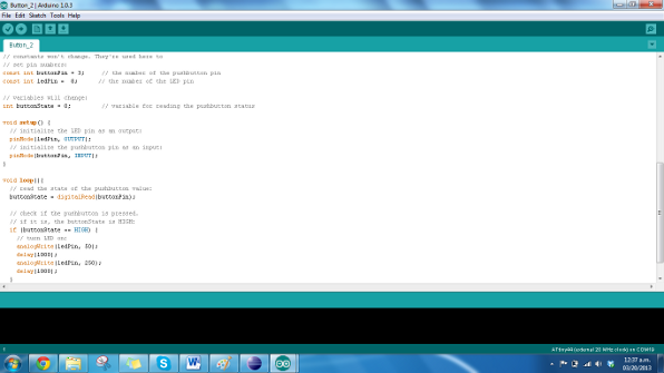
To program the board using the Arduino IDE, I did nothing of research. The Arduino IDE uses C++ with lots of embedded libraries to simplify the coding. It is great to dive into coding, altough you lose some control over the code. I have no problem with that so far, although it is good to learn C coding for any other application in the future. For the Arduino IDE code, I just edited a little bit the Button example that comes with the IDE, and the board worked like a charm, doing the same thing as I programmed before with C. The code can be found here.