Caution! José Figueroa at FabAcademy 2013
Weekly report of my work at FabLab Barcelona
For this assignment we had to create a simple network of two nodes and make them communicate. For my assignment I chose serial communication as the communicating channel between the nodes. Serial communication is made by connecting the receiver pin of one node to the transmitter pin of the other node, and viceversa. Through that physical connection, a series (hence the name, serial communication) of 0 and 5 Volts representing 0's and 1's are exchanged between the nodes. The microcontrollers in the nodes get that stream of voltages, or data, and get useful information out of it through embedded code.
The first node in my assignment is the board I made for the Week10's assignment: Input Devices. Back then I milled and soldered Neil's Hello Mic board. Well, I actually did it a few days after Week10, but the assignment was for that week's lecture. I managed to program that board using the Arduino IDE, so little change was made to the original code, only adding a "#" symbol at the beginning of each line of code where the sensor output is sent through the serial port. Here is the code for that first node.
The second node is the board made for Week 6: Electronics Design. That board had FTDI connection and an LED, so I was curious about making it work with another Attiny through serial communication. The "#" symbol mentioned earlier was included in the code, as a way of signaling the beginning of the streaming of data to help with the parsing of serial data on the second node. Parsing is a bit difficult to do, but luckily there are Arduino functions that do that for you, like Serial.parseInt, which is the one I used in the code of the second node. All that I do is tell the code that each valid integer value is preceded by the "#" symbol, that way I can securely separate between readings. The next part of the code is just a simple constrain on the values of the reading so I will always have 255 as the top value, which is the top value for the PWM signal sent through the analogWrite Arduino function.
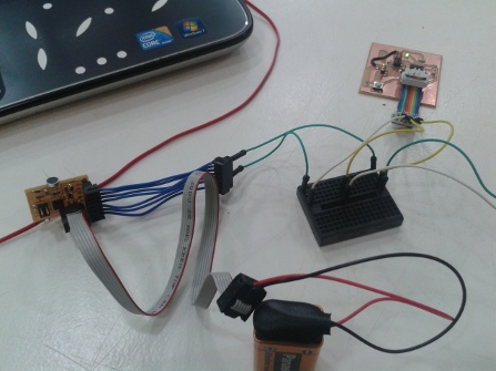
Therefore I had two nodes, one which had an input device (electret microphone), and the other one had an output device (the LED). They were both communicating through serial communication, in which the transmitter pin of node 1 was connected to the receiver pin of node 2. Therefore, node 2 got input information that it processed for its output device. The final goal was to convert the electret microphone readings into light intensity of the LED. Much work needs to be done in the signal processing, such as a better amplification for the microphone and maybe some filtering on the signal. The networking part was tested and worked well.