Vacuum form machine
Simple and effective
- Notes on mercurial
Notes on webdesign
Notes on digital drawing
Notes on 2D cutting
Notes on electronics production
Notes on 3D scanning and printing
Notes on electronics design
Notes on molding and casting
Notes on embedded programming
Notes on computer controlled cutting
Notes on input devices
Notes on composites
Notes on interface programming
Notes on output devices
Notes on networking and communications
Notes on machine design
Notes on the final project
Final Presentation Notes on Invention, Intellectual property and Business model
Notes on Electronics Design
As I've said before I'm a complete novice when it comes to electronics and circuitboards. The classes felt like I was sitting in on a foreign language meeting and not understanding one bit of it. When we eventually started out building the board the in Eagle software it wasn't long before I was completely lost. I had to ask my fellow students and my guru multiple times what the heck I was doing wrong now! Eventually I got the hang of it and my first PCB design was just a copy of Neil's original board... With an added Batman logo, which I added in photoshop... Don't hate me!
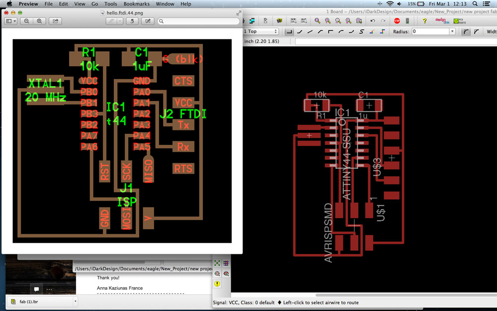
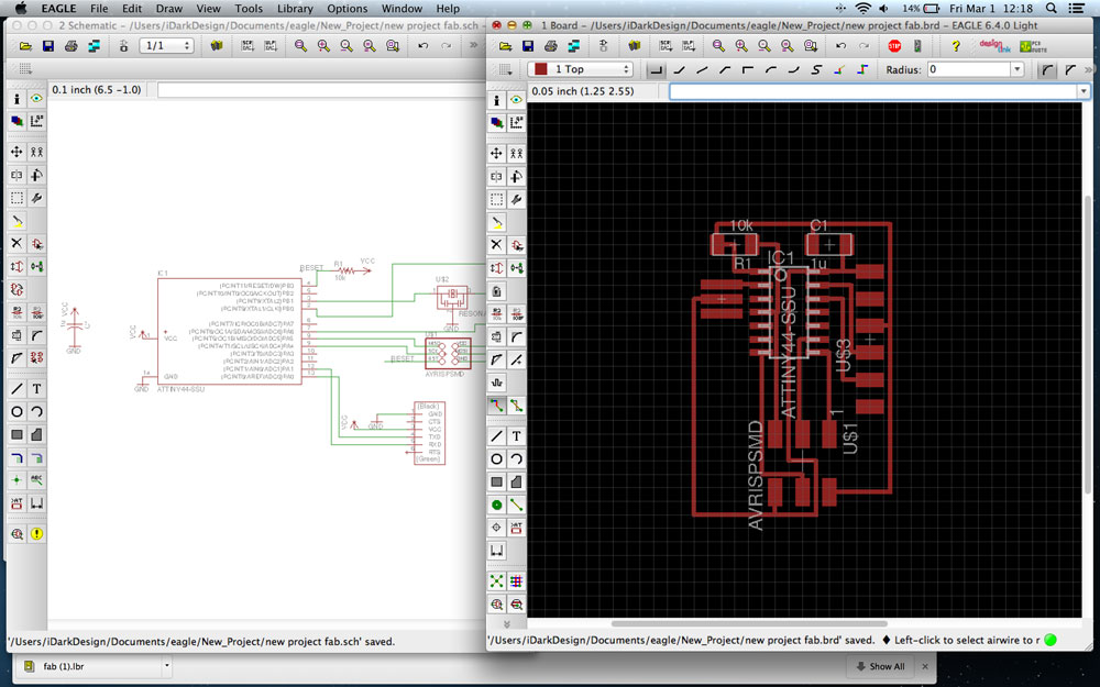 Here is my carbon copy of the Hello-world PCB. As you might be able to see I connected the pins with lines but also with coded lines (ie not visually connected)
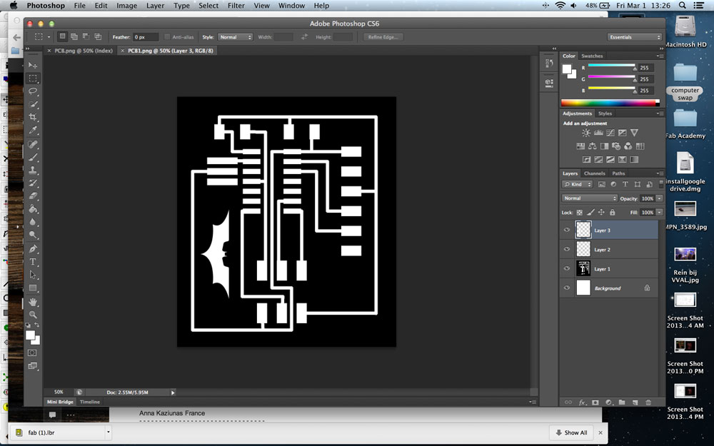 I added the batman logo for some fun but I ended up discarding it again in favor for more LED's!
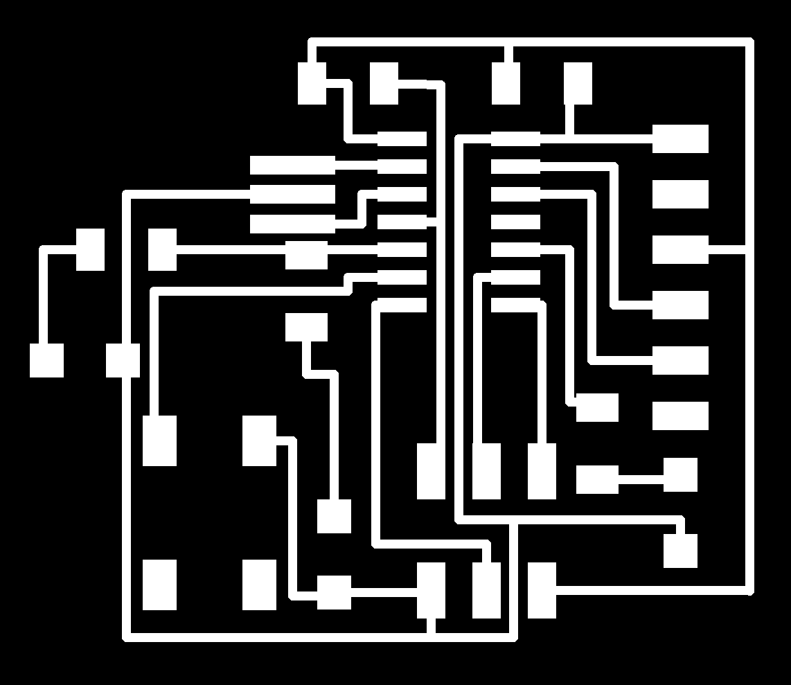
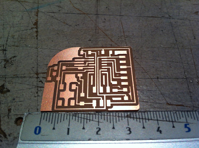
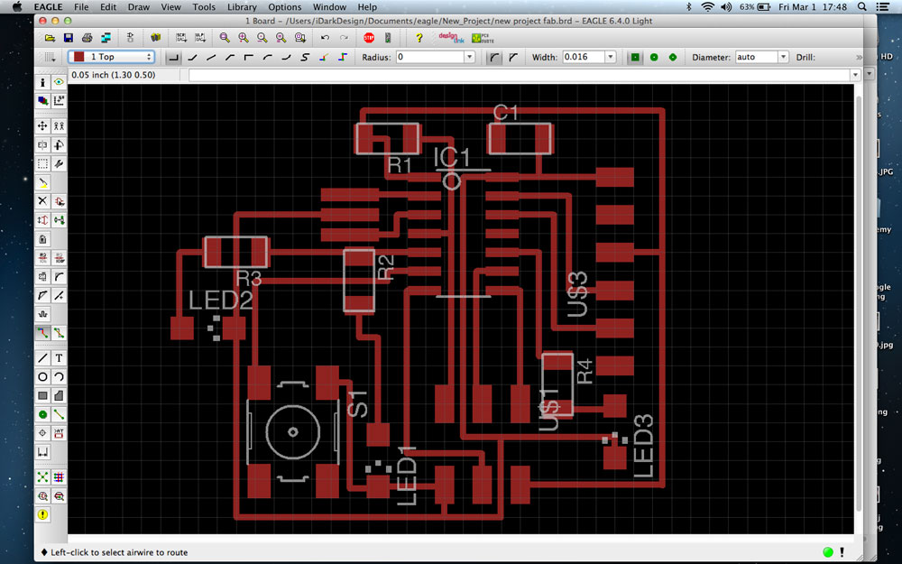 I ended up adding three LEDs on my board. Two are connected to the same pin while the third one is connected to a seperate pin. I'll have to think of a good reason to have the LEDs light up seperately from each other. It was a pain to route the connections under each other and with enough tolerance for the Modela to be able to still mill the traces. Eventually I got it and I added some round corners too. These are the .png that went to the modela:
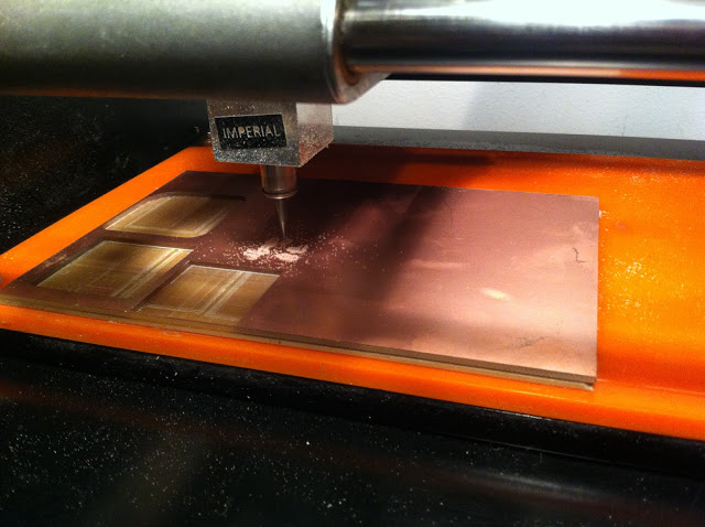
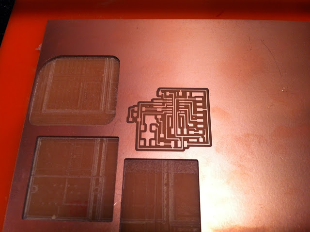
Milling the board was easy having done this before a couple of weeks ago.
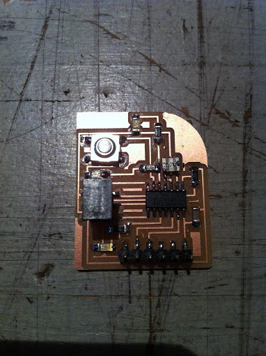
Soldering on the LEDs was a little tricky. We had to discover on our own that the green line on the LEDs needs to go toward the cathode. After the board was soldered together I used a multimeter to see if the LEDs worked properly and if I didn't have any shorts in the board. All was done well. Now to program the shit out of this puppy!
top