Vacuum form machine
Simple and effective
- Notes on mercurial
Notes on webdesign
Notes on digital drawing
Notes on 2D cutting
Notes on electronics production
Notes on 3D scanning and printing
Notes on electronics design
Notes on molding and casting
Notes on embedded programming
Notes on computer controlled cutting
Notes on input devices
Notes on composites
Notes on interface programming
Notes on output devices
Notes on networking and communications
Notes on machine design
Notes on the final project
Final Presentation Notes on Invention, Intellectual property and Business model
Final Project Presentation
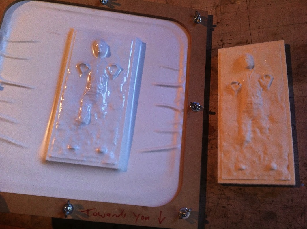
It might not be carbonite but it will hold Han safe on his trip
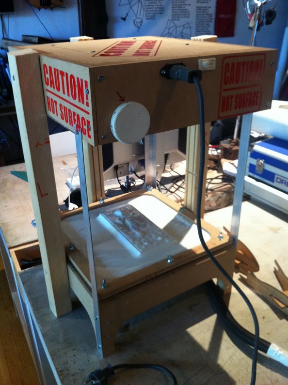
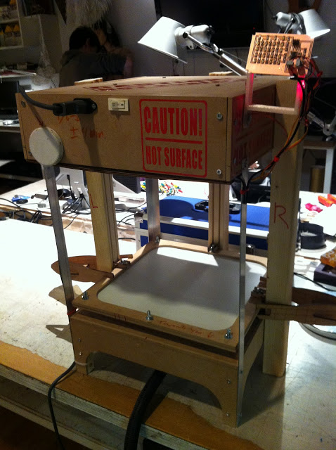
I had to shelve the full-size vacuformer and decided to work hard to achieve a 'simple' desk vacuformer. (if you place this on your desk, you will need another desk to work at!) Working on this project I confirmed once more that I'm not one for exact sciences. I just don't get it. The machine itself was a breeze to design and put together but when it came to electronics I spent hours on end staring at the code and the schematics. To the point that I just wanted it to end. I was not enjoying it anymore.
The Final Project Notes
what will it do?
The vacuformer will be able to vacuform molds from items in the 25cm x 25cm range with plastics variable in thickness (up to +- 1mm thick)
who's done what beforehand?
I have collected a lot of research in the last months. From resources like instructables and blogs around the subject. I think the machine basics are simple and the challenge for me lies in introducing sensors and lights to this machine.
what materials and components will be required?
I will require:
- Wood
- Heater element
- Temp sensor
- light sensor
- aluminium/ aluminium foil
- Vacuum cleaner
- vynil sticker
- Power supply
where will they come from?
I have sourced a second hand heater element from a 1000w electric oven. I'm sure this will suffice. All other materials I'm sure to get from the lab storage.
how much will it cost?
I have sourced the oven for a mere €15. As all the other materials will be supplied by the lab I'm sure I can make this for under €50
what parts and systems will be made?
I will make a heating container to heat up the plastic. I want to make a working elevator to drop the plastic over the mold. I want to incorporate a temp sensor and a light sensor as well. Also if possible I would like to use molding and casting to make parts of the machine.
what processes will be used?
I will use eagle and the modela to make the PCB's. Soldering to finish them. Also the shopbot for cutting all the wood. The vinyl cutter for some labels and finally the laser to cut small pieces and prototpe.
what tasks need to be completed?
First to dissasemble the heater oven and build that in a working isolated box with a way to fix the plastic under it. I need to figure out how to wire the light sensor and the temp sensor in the machine and have it work together.
what questions need to be answered?
Will it blend?!
what is the schedule?
I will start with taking apart the oven and working it's innards into a box. Then I will make the wood structure of the machine and then the sensors.
how will it be evaluated?
Probably by my tutor and peers.
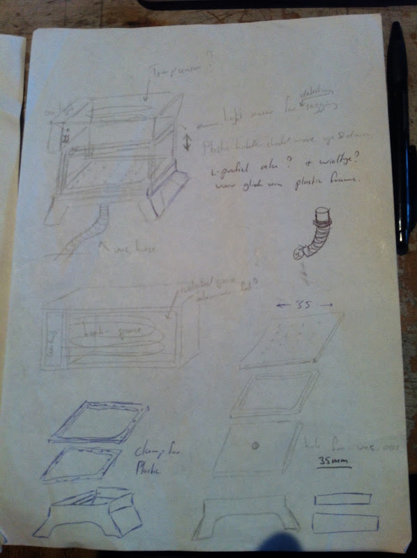
Like all good ideas I started doodling this on some paper. (napkins not available!) I drew up general measurements and ideas for shapes of the components.
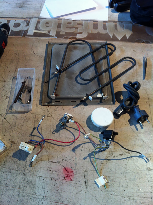
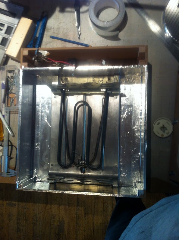
You can see that I have incorporated parts from a small oven. I scored one secondhand on marktplaats. It was advertised at €15 but I got it for only €10! I took it apart and scrapped most of it. The heater elements are very simple but still I had to tag all the wires with numbers to and tag their respective connections. Just to be sure.
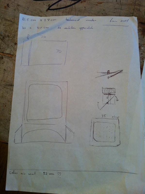
I then drew up plans for the shopbot and loaded some 6mm MDF on to the table to be cut. I used a 1/8" 2 flute down spiral milling bit to cut all the pieces. I had to programm the shopbot to cut at least a full millimeter below the 6mm MDF. The sacrificial layer was just not completely level. Always remember to programm the toolpath so that it cuts the inside toolpath first (top) and to have the final cut run on the outside path.
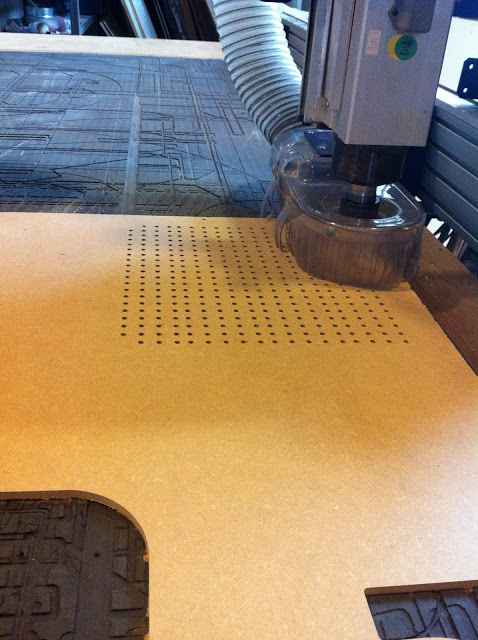
I had to drill a lot of holes. To save the milling bit I opted to use a regular 5mm drill. Always do the drilling before the milling. The shopbot has an option to calculate a 'drilling toolpath'. Make sure that the holes you want to drill are the same as the drill you are using. A drillbit is not a millingbit.
I laminated most important parts together and hooked it up to a shopvac to see if it would work! (I used a piece of vinyl)
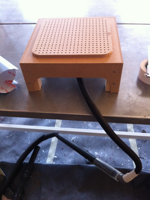
It works fine. The better the vaccuum the better the pull. I use a Kärcher industrial vaccuumcleaner for this now but I would love to hook it up to my Dyson or even the shopbot compressor!
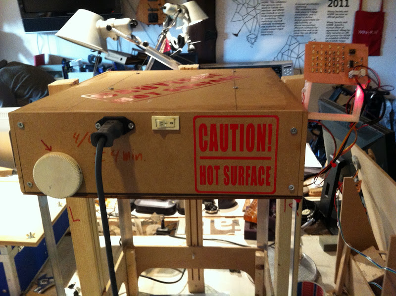
To prevent the MDF from catching fire I covered the oven-box in aluminium tape. This will radiate most of the heat away from the wood. I recycled a piece of the metal holder from the oven and raised it on 2 square beams of isolated wood. I also created a compartment for the all electronics.
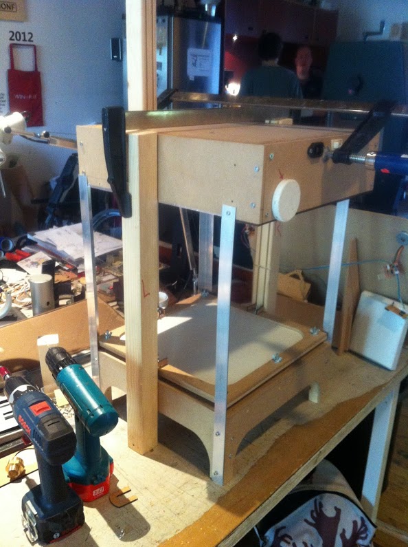
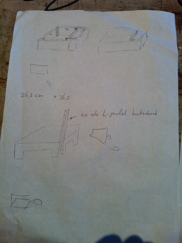
I created a rails system by carving up a beam on the shopbot. As these are just 2 straight lines I wanted to manually manage the shopbot to do this and not have to draw up a seperate vector file for it. I mounted the beam on the sacrificial layer and started cutting by using the arrow controls. While I was paying my utmost attention I managed to drive the bit a couple of cm to far and it broke. To prevent this; instead of just using the arrow controls use the coördinate-controls. Zero the machine (X+Y) and send the bit down (5mm steps) and send it to a pre determend coördinate. This way you keep full control of the milling bit. This is also very usefull for seperating milled pieces from still usable sheets. That way you can scrap the used piece and have a couple of nice straight sheets in storage instead of full sizes stencils.
With the machine together it was time to start working on the electronics.
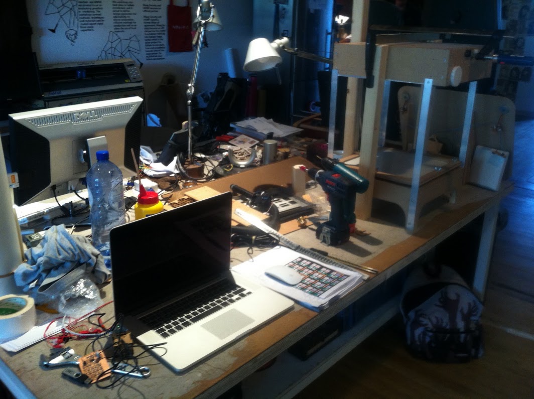
I tend to 'collect' stuff on my desk.
I started with making the hello.reflect.45 board. I wanted to join the reflect and the array board in one board. But as I had not made the former yet I wanted to understand it first. While milling the board on the modela I realised to late that my resolution was too little for the fab modules to create a proper outline. On top of that the board started milling on the wrong zero. (I don't know how that happend)
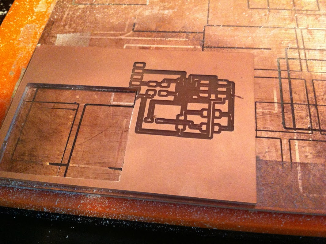
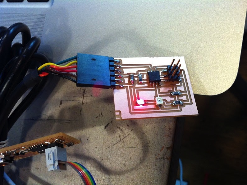
After I exported my trace image in a bigger resolution (I used 800dpi) I had no problem with the fab modules generating a proper milling path. I used a red LED instead of a infrared one so it's easier to see if it works. After soldering and flashing the board everything worked fine.
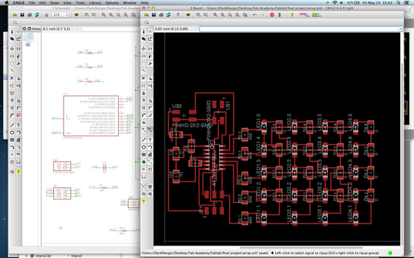
I fired up Eagle and started working out the hello.array.44 schematics. I wanted to do this so I could learn how to charlieplex and add other components to existing PCB's.
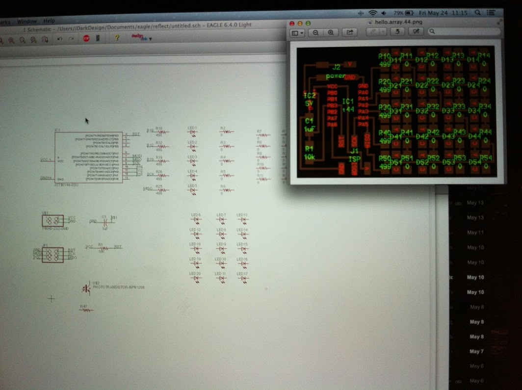
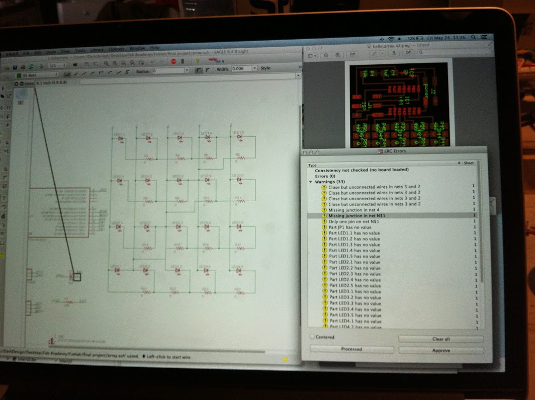
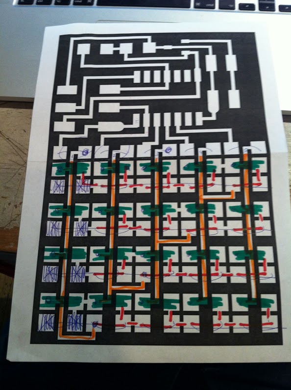
I could not wrap my head around all the connections. With help from guruBas I finally got a small understanding of how it works. I had to print the original traces and colorcode me to finally understand what was happening. I removed three of the 0 ohm resistors and added a connector to two of the unused pins for the LED and the photoresistor to connect to.
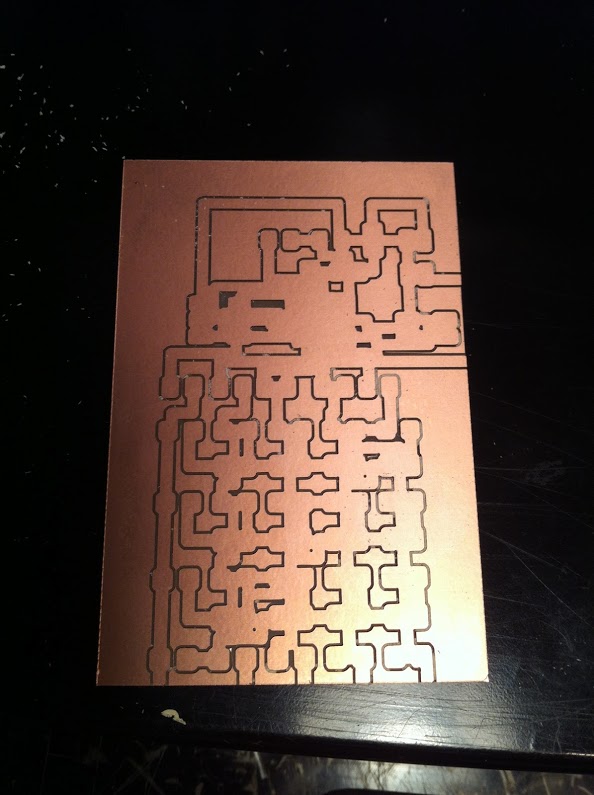
Somehow my settings in eagle produced a very large path. So big that it didn't even fit on one board! After adjusting a few settings it milled out fine and I was able to solder it all together. Now the 'fun' began....
At first I just used the standard hello.array.45 code and I wanted to add the reflect code to it. After 2 hours of reading the code and not understanding it I decided to ask for help. A friend opted to connect the reflect board to the array board directly instead of wanting to adjust the code on the array board.
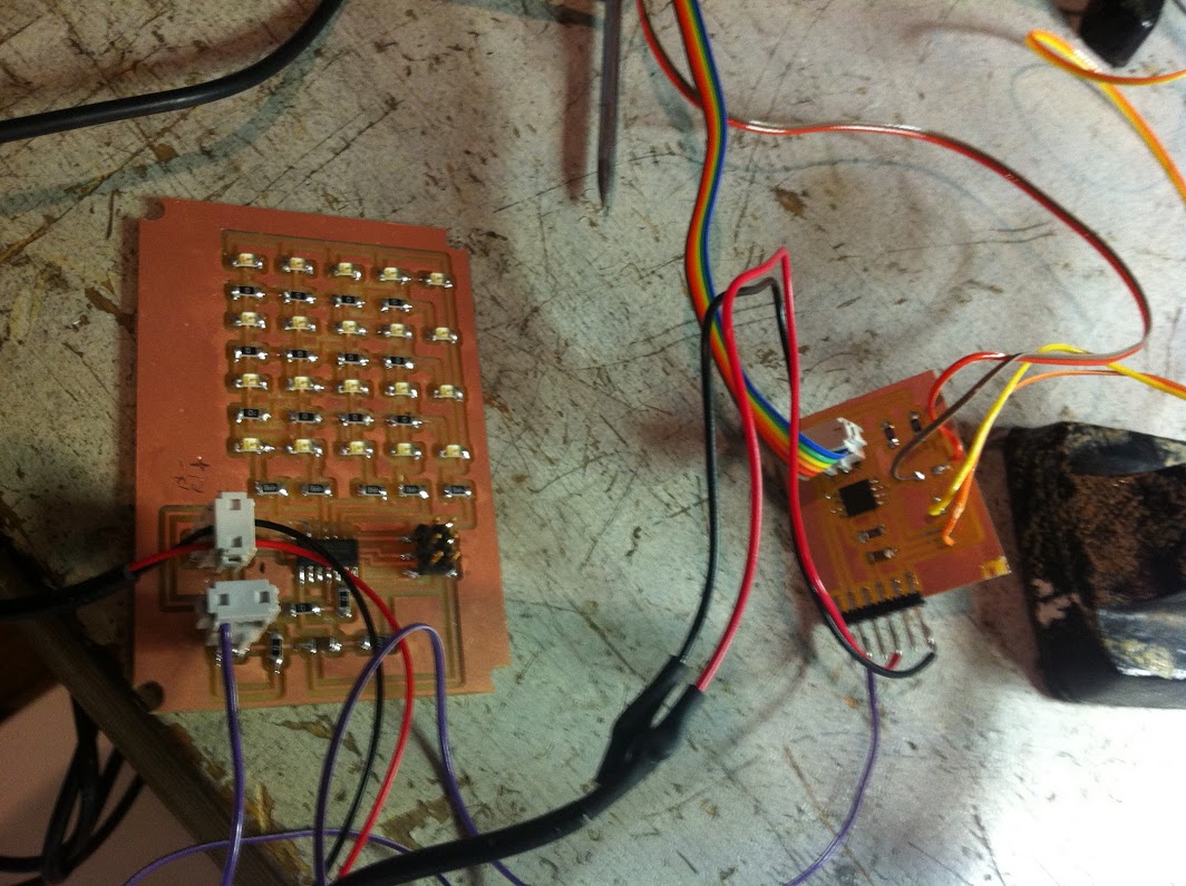
To power the two boards from the 230v coming from the oven wiring I butchered an old ericson phone charger (230v AC in 5.4v DC out). I managed to butcher it so much that I had to lasercut a new container for the condensators. I hooked the socket connectors on the + and - before the on/off switch so it will power even if the heater is off.
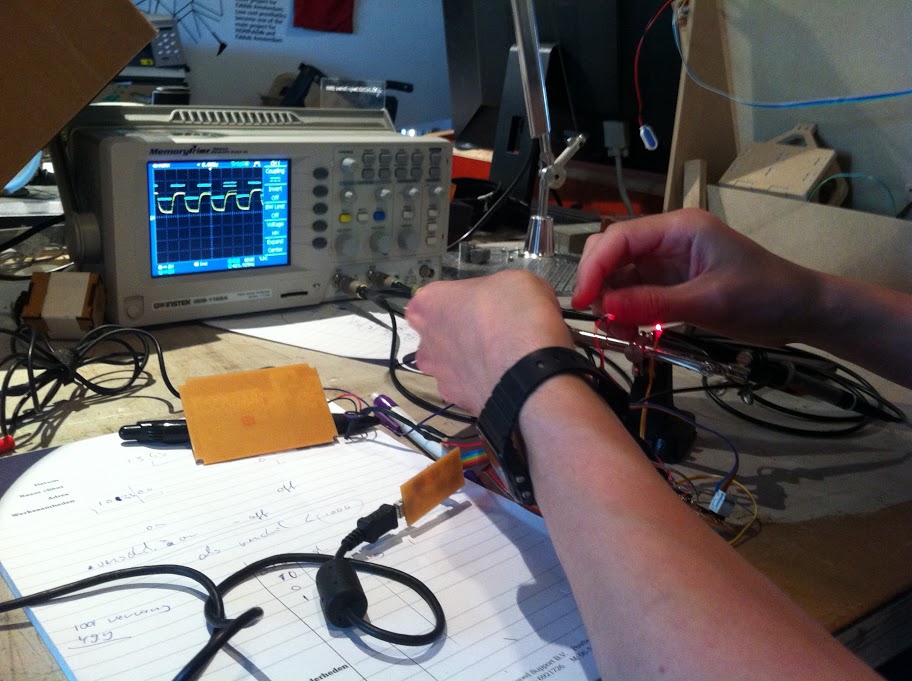
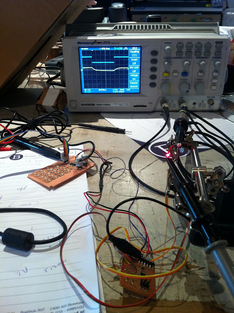
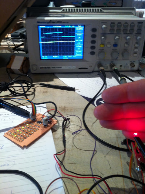
My original idea was to have the light reflect sensor on one side of the machine and the LED on the opposite side in the rails system. This way it could detect the sagging of the plastic and as the plastic was hot enough the plastic would break the line of sight. If the line of sight was broken the signal would change and start the LED array signaling the user that the plastic is ready to be vacuformed. With the help of guruBas I discovered that the sensor board was not able to identify the signal when the photoresistor is further away than 6cm's. This was quite a surprise. I even brightend the LED (I replaced the 1k resistor for a 49.9 resistor) but it would not be enough. I had no idea what else I was going to do so I decided to keep pursuing the 'line-of-sight-is-broken-LED-array-lights-up'. Another couple of hours staring and not understanding the code I planned a guruhour with guruBas. With Bas' help I finally managed to program the reflect board to send a '1' to the array board when the line of sight is broken. I didn't need more. When the array receives a 1 all the LED's light up. I added a small string of coördinates to the code so the LED's would go back and forth.
flash(B,A,delay); flash(C,A,delay); flash(D,A,delay); flash(E,A,delay); flash(A,B,delay); flash(C,B,delay); flash(D,B,delay); flash(E,B,delay); flash(A,C,delay); flash(B,C,delay); flash(D,C,delay); flash(E,C,delay); flash(A,D,delay); flash(B,D,delay); flash(C,D,delay); flash(E,D,delay); flash(A,E,delay); flash(B,E,delay); flash(C,E,delay); flash(D,E,delay); flash(C,E,delay); flash(B,E,delay); flash(A,E,delay); flash(E,D,delay); flash(C,D,delay); flash(B,D,delay); flash(A,D,delay); flash(E,C,delay); flash(D,C,delay); flash(B,C,delay); flash(A,C,delay); flash(E,B,delay); flash(D,B,delay); flash(C,B,delay); flash(A,B,delay); flash(E,A,delay); flash(D,A,delay); flash(C,A,delay); flash(B,A,delay);
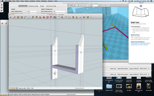
Because I still wanted to present the electronic part as part of my final project I designed a small display for the electronics. I used Sketchup to design the files and printed it on an ultimaker.

The first try the PLA filament would not stick to the tray and after a few lines it warped and curled up.
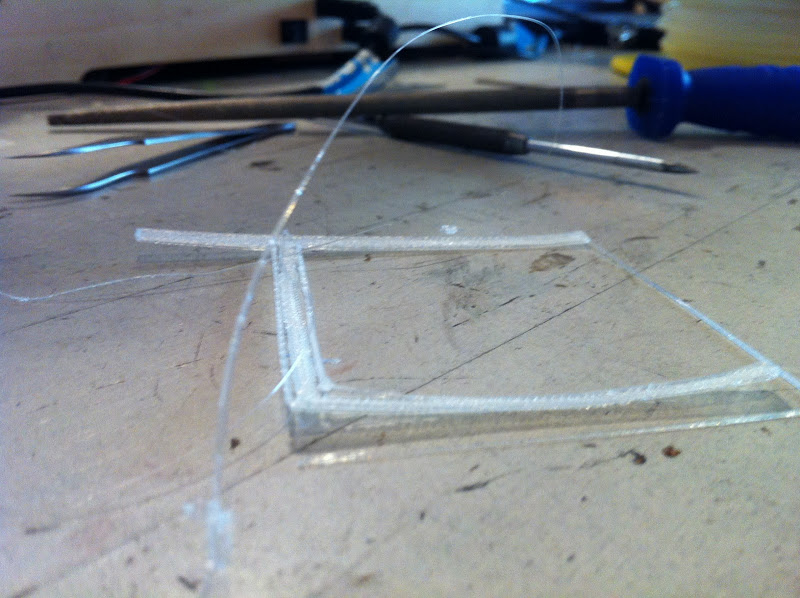
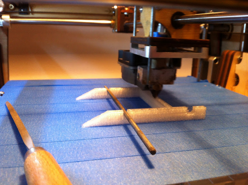
Then I discovered (while printing) that I forgot to imply the support structure. I had to think quick and found a solution in some nearby tools.
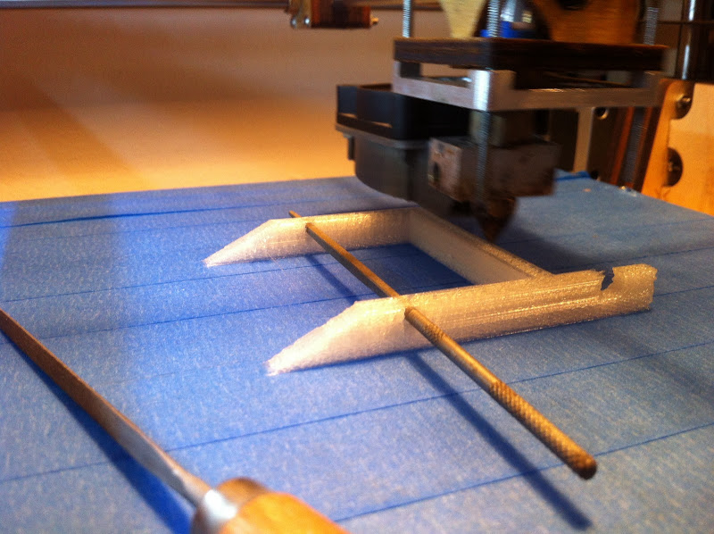
Works like a charm!
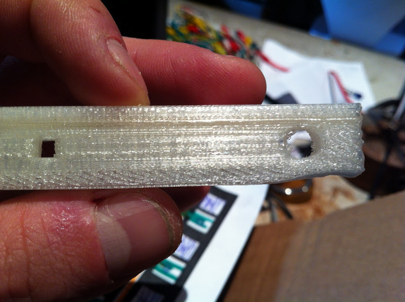
Somehow the plastic structure was very weak at a few spots and would come apart. I used a heat gun to stick the PLA together again. This warped the plasti a little but it can still be used.
Stickers!
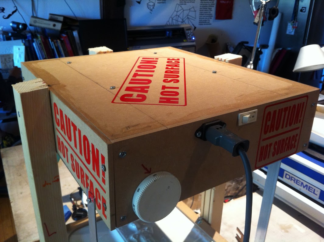
I had to cut a few labels for the oven part of the machine. I cut these from red vinyl.
Time to pull some plastic! The first pull I tried multiple objects.
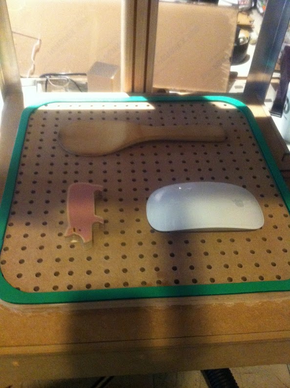
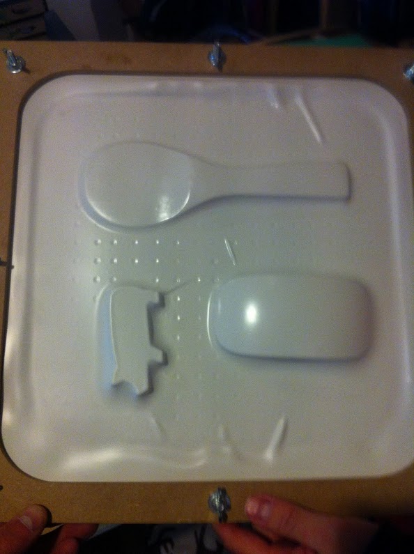
I was very satisfied with the results!
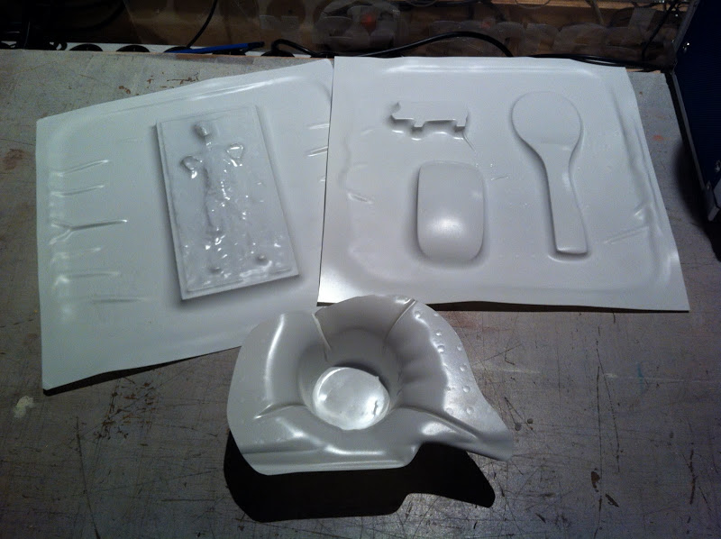
I have used various thickness' of polystyrene sheets. It generally takes up to 4 minutes for the plastic to be fluid enough to be able to pull a mold. The machine could use a little more suction power. I think this will help with corners. Especially near the floor.
I have collected all my vector files in one .eps
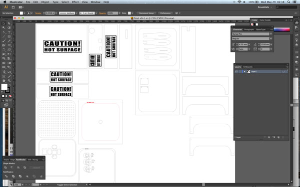
The code I used and the designfile (.ai) files can be found here
Bill of materials:
- second hand oven
- leftover sheet of mdf from the lab
- leftover wooden beams from the lab
- 2 aluminium profiles cut in half
- aluminium tacked foil
- Plumbing connection pieces from old stash
- Vacuum hose from old stash
- screws, nuts and bolts
- PLA for the 3D printed frame
- circuitboard + components for the array from the lab
- Sheets of polystyrene plastic from the hobbyshop
- vinyl for the labels.