Networking and Communications
Description
I will try to make an attempt to maybe make something that should look and maybe even act like a network of microcontrollers.
Making a quick and tiny board
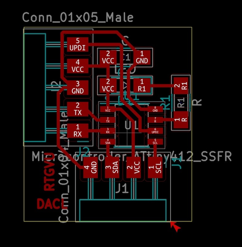
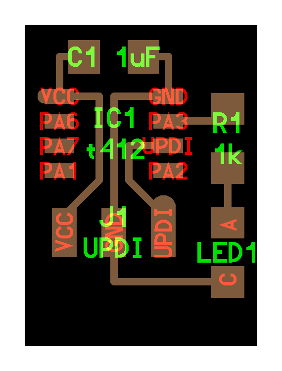
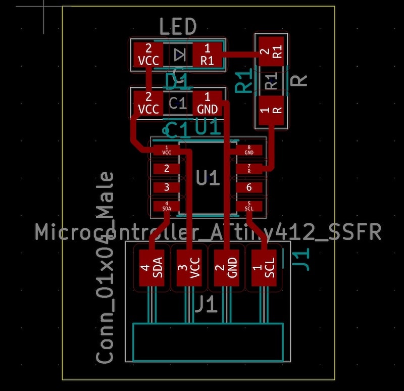
I start by making a quick and tiny board based on the ATtiny412. I want to use the I2C protocol as this seems to make most sense to learn; it has the best of both serial and ISP worlds.
I figured that if I make a small board that contains the following, I am almost done:
| COMPONENT | DESCRIPTION | DATA SHEET | SPECIFICATIONS |
|---|---|---|---|
| ATtiny412 | 412_datasheet.pdf | polarity | |
| R LED | datasheet? | polarity | |
| UPDI extended with RX, TX and VCC | To allow board programming/serial communication. | see notes below | polarity |
| SCL and SDA pins | To connect the other boards to | see notes below | polarity |
| Capacitor | To stabilize power signal. | 1µ | |
| Resistor | Resistor for the LED | 1KΩ |
NOTES
The UPDI extended pins are an invention by me. As I noticed in the past that the FTDI has two pins I never use (DTS and RTS), I might as well remove them. Also, both UPDI and FTDI bring GND to the board; this is also an unnecessary redundancy. By combining the functions I use from FTDI and UPDI into one pin, I can lower the footprint of the board and create potential unexpected problems for future-me in one go!
So the 5 pin break out on the board contains:
- VCC
- GND
- UPDI
- TX
- RX
Then there is the SCL and SDA pins going to the students boards. Next to these two pins who basically govern the I2C communication, they also need power and GND. So this live on the pin as well. There are fancy 2x2 upwards facing and surface mount components in the inventory, but I couldn't find their footprints in the Fab Library in KiCad. So I went for a regular 4 pin to deal with this. The downside is that for the busconnection I probably have to resort to a breadboard and can't use the fancy connecters that you can clip on a cable... but oh well, as long as I get I2C communication going, I'm happy.
Milling is fun!
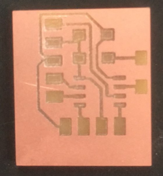
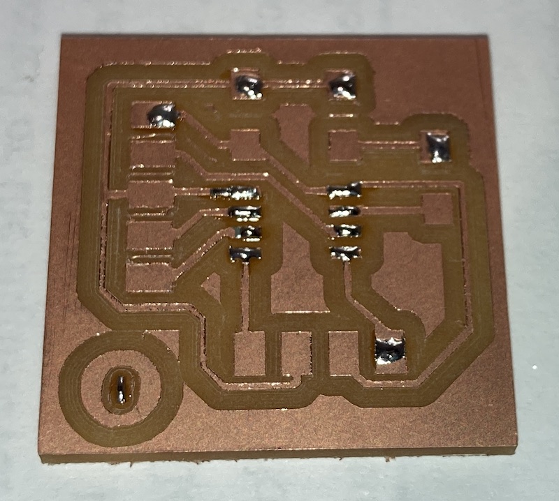
So, because my board is simple. Because my board is tiny. And because I care more about a fast finish then a good finish I decide to already mill my board on thursday afternoon after the local lesson. I quickly pop in the right mill, instruct mods to do my bidding and marvel at the fact that a mere 20 minutes later my super tiny board is already ready.
and it is a beauty!
Sadly life looses all meaning quickly thereafter when a smart-ass colleague student points out I milled the thing in inverse... as if all air is suddenly sucked out of the room I silently wander of into eternal void.
Milling if fun! Part 2.
In the evening of thursday I took the time to review my board and came up with a slightly different version to mill the next day.
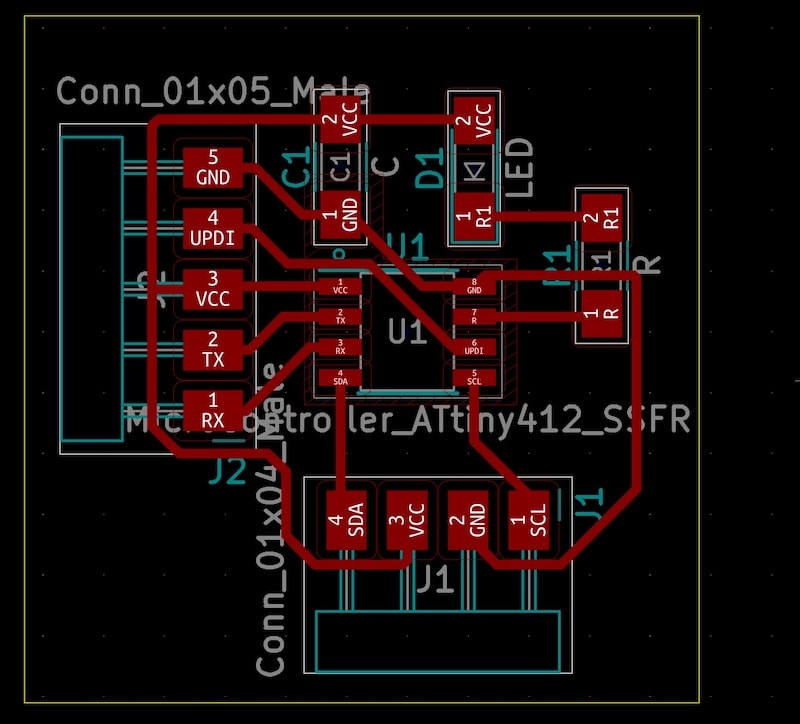
It has the same characteristics as the board above. Apart from the lettering; I was considering putting some letters on the board to help me find the right pins. But these letters never come out as nice as you want to and, I thought, I can also note it on the backside with a marker.
As we are making a network this week I have to create multiple boards that together will make up the network. So the board you see above is what I call the 'teacher' board and next to that I am going to make three 'student' boards. Whether the students will listen to what their teachers tells them remains to be seen...
The student boards.
I make three student boards that consist of
| COMPONENT | NOTES and/or DATASHEET | SPECIFICATIONS |
|---|---|---|
| ATtiny412 | 412_datasheet.pdf | polarity |
| LED | datasheet? | polarity |
| SCL and SDA pins | To connect the other boards to also see notes below | polarity |
| Capacitor | To stabilize power signal. | |
| Resistor | Resistor for the LED |
Note that on all boards I am using female pins as I have found myself daisy-chaining male-to-female pins very often in order to connect boards. Also, I will for sure need a breadboard to make up the serial bus and so the use of male pins is unavoidable. Better have female connections on both sides then...
NOTE about polarity and LEDs
It may be worth noting (again) that LEDs have polarity. They have an anode and a cathode. An LED also needs a resistor. The anode of the LED has to connect to the resistor.
I inferred this from neil's blink board and also wrote about this in week 6.
Finding the right part.
For the student boards I need a four pin SMD to route the SDA and SCL. I can't seem to find this in the fab inventory library. So I resort to also using a female 4 pin for this.
Final board layout
In the end I make a student board that look like this:
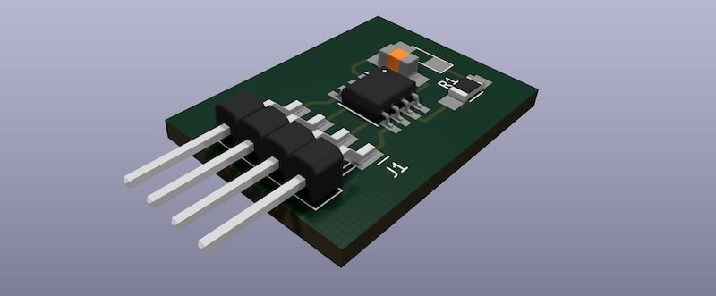
The teacher board files can be downloaded here The student board files can be downloaded here
The actual milling.
Against henks advice I am going to try to mill all four board (one teacher, three student) in one go. I am going to put them in one PNG and load that in mods. Obviously the main thing that can go wrong is that the cutout is missaligned and kills some of the traces.
We'll see...
Step by step
In the exporting of the board I find that there is a an option i had overlooked so far:
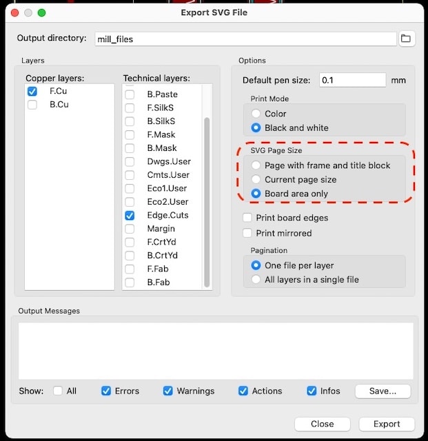
Selecting 'Board area only' greatly improves the precision of the exported file and the change that my plan will work!
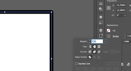
I use illustrator to open the SVG's and then export to PNG. There are also a few adjustments I can do in this step, as making the cutout line thicker. A tiny cutout line seems to be missed by mods. And I need to go back and forth a few times to find out what works and what doesn't. In the end there is a long chain of trial and error and I am not yet entirely sure what are the optimal settings for a nice and clear cutout.
Note In a later session I do find out what the magic sauce to make this work is: the drillbit is 0.8 mm. The cutout trace needs to be at least 0.8mm to be found by mods. Also, you can make all area black outside the cutout line to prevent mods from thinking it has to cut on both sides of the cutout line.
This last things is partly due to other results at home, when using modprojects, then when at waag and using the mods installation there. More funding and research is needed.
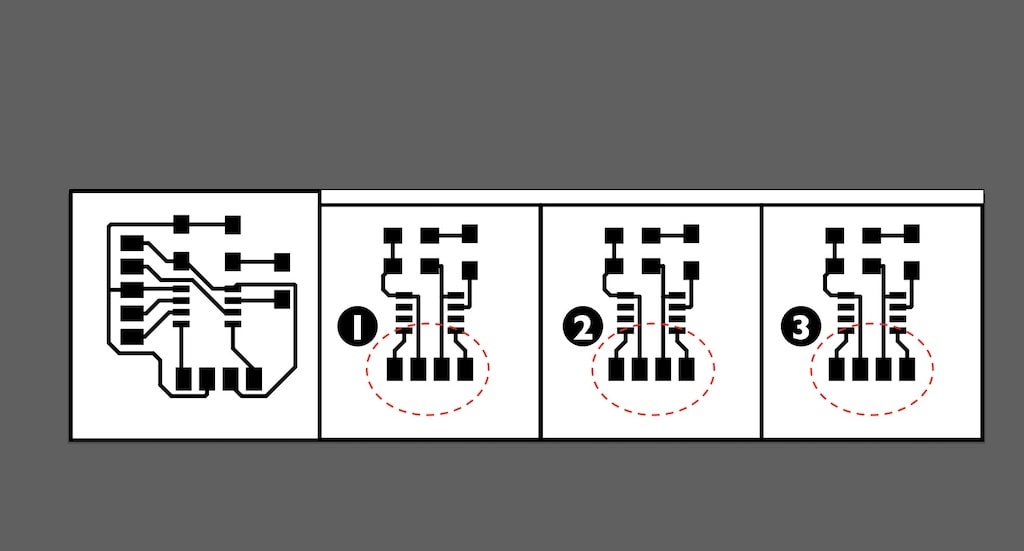
Finally I place all files, traces and cutouts in one file and export that as a PNG.
And only now it dawns on me that for daisy-chaining the student boards to the bus I might have had to use a different connector... There will be no other option then to use a breadboard afaik to make an I2C bus with these connectors.
And then we mill...
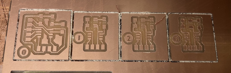
Yes, they seem not well aligned. They seem to lean somewhat to the left. But I think this is actually a visual disillusion, because when you overlay the two images.... it turns out this is just exactly as they should be!
The size of the number and its circle, and that the mill mills around the circle, make them tilt left visually.
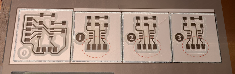
So I think it is possible, with a bunch of tiny boards, to put them on ONE png and mill them in one go.
Soldering
I collect the parts from the inventory and use the small USB soldertip to make my boards. I first put a little solder on all MCU pads and the halve of the pads of the other components. I like how this allows me to quickly make stuff stick when I heat it and solder it better when I have both hands free again.
After soldering I hook the boards one after the other to my own funny UPDI/FTDI-mesh to I can program the boards with a simple blink program to test them.
The testing reveals only a few minor soldering issues which I can quickly repair on the spot. And in the end all four work.
Note that I had to use a special clipper to connect to the UPDI port on the student boards as I didn't break this one out.
Programming the boards.
This is the hardest part, as, frankly, I have not really an idea where to start... I took the code from the group assignment from the student and the teacher boards. My hunch is that I have to upload these pieces of code to the boards. But then the question remains: how do I define which address each board gets..
For starters I hooked everything up to a breadboard. Funny thing is that all LEDs start working as soon as there is power. This is because I already uploaded a blink sketch to test if they work. They all light up at the same time when power in on. But they very quickly go out of sync. Why is this? They are all ATtiny412s...? They are almost identical... And will connecting over I2C solve this?
So many questions... And I really do not know where to start... after a day full of googling, I was not really any closer to finding what to do. Luckily Henk directed me to an instructable that seemed to contain most of the information I needed.
Size issues
I start by using this code for the teacher node. But quickly run into errors...
Arduino: 1.8.13 (Mac OS X), Board: "8-pin ATtiny412/402/212/202, ATtiny412, 20 MHz internal, 1.8V (5 MHz or less), Disabled/Disabled, EEPROM retained, Enabled (default timer), UPDI (no reset pin), 8ms, Ignore (saves flash, almost always fine)"

/Library/Arduino15/packages/DxCore/tools/avr-gcc/7.3.0-atmel3.6.1-azduino4a/bin/../lib/gcc/avr/7.3.0/../../../../avr/bin/ld: address 0x12dc of sketch_may04a.ino.elf section `.text' is not within region `text'
/Library/Arduino15/packages/DxCore/tools/avr-gcc/7.3.0-atmel3.6.1-azduino4a/bin/../lib/gcc/avr/7.3.0/../../../../avr/bin/ld: sketch_may04a.ino.elf section `.rodata' will not fit in region `text'
/Library/Arduino15/packages/DxCore/tools/avr-gcc/7.3.0-atmel3.6.1-azduino4a/bin/../lib/gcc/avr/7.3.0/../../../../avr/bin/ld: address 0x12dc of sketch_may04a.ino.elf section `.text' is not within region `text'
/Library/Arduino15/packages/DxCore/tools/avr-gcc/7.3.0-atmel3.6.1-azduino4a/bin/../lib/gcc/avr/7.3.0/../../../../avr/bin/ld: region `text' overflowed by 898 bytes
/Library/Arduino15/packages/DxCore/tools/avr-gcc/7.3.0-atmel3.6.1-azduino4a/bin/../lib/gcc/avr/7.3.0/../../../../avr/lib/avrxmega3/short-calls/crtattiny412.o:../../../../../crt1/gcrt1.S:315:(.init9+0x2): relocation truncated to fit: R_AVR_13_PCREL against symbol `exit' defined in .fini9 section in /Library/Arduino15/packages/DxCore/tools/avr-gcc/7.3.0-atmel3.6.1-azduino4a/bin/../lib/gcc/avr/7.3.0/avrxmega3/short-calls/libgcc.a(_exit.o)
collect2: error: ld returned 1 exit status
exit status 1
Error compiling for board 8-pin ATtiny412/402/212/202.
A first hunch is that the library and sketch I am trying to upload is actually too big for the 412... but that would be absurd... right...? I mean... someone would probably have said anything about this... or have they and haven't I been paying attention...? argh.
I compile the sketch for an Arduino Uno and get as output: Sketch uses 5406 bytes (16%) of program storage space. That is 1.406 byes more then fit on a 4KB Attiny 412...
So yes. The wire.h library needs to be altered by me in order for this to work, or I need to find an I2C library with less overhead. Following that last link I end up reading about this alternative, but it seems also to complicate stuff a lot more... On the github page of the project I read that
The main difference between these routines and the standard Arduino Tiny Wire library is that these don't use buffers, so have minimal memory requirements, and don't impose a limit on transmissions.
So there is also a an Arduino Tiny Wire Library?!
A google search and some more click lead to this page that seems to be really old.. and mainly talks about the Attiny85. An even older and smaller version of the 412...
But it contains one very important reassuring sentence...
USAGE is modeled after the standard Wire library . . .
And I decide to check how I can download and install libraries in the Arduino IDE. I download the Libray as zip file following this direct link: TinyWireM.zip
I was hoping to find an readme in the unzipped folder, but there is nothing there...
Ofcourse, just going to ~/Documents/Arduino and looking for the libraries directory helps a lot. I open the directory and find there is already an TinyWireM directory inside!
(and a readme file with the text: For information on installing libraries, see: http://www.arduino.cc/en/Guide/Libraries)
And there I learn that, just as with boards, you can also add and remove libraries from the Arduino IDE... and I learn that the TinyWire library is now maintained by Adafruit. With a commit only 10 months ago I believe this is project is in good hands and I continue my own saga.
Continuing where we left off: programming the boards.
Remembering the part:
USAGE is modeled after the standard Wire library . . .
I am so bold to just replace one library with the other in the sketch...
so this
#include <Wire.h>
becomes this
#include <TinyWireM.h>
what could possibly go wrong...?
It turns out that so much can go wrong, that I created an extra file for the error codes so my whole page layout doesn't break.
I found a page of last years fabacademy student Yunje Choi who seems to have come about as far as I have. And then gave up.
Luckily it seem that there are many more Fabacademy students who have wrestled with this library. I have some reading to do it seems...
Starting with OpenDots Christiana Giordano adventures from 2017:
Findings:
- There is TinyWireM and TinyWireS.
- The first is for teacher (master) nodes, the second for student nodes.
- You need to have both installed.
- The library from Ada is TinyWireM.
- TinyLibraryS can be downloaded from the wiki page of Emanuele Goldoni]
- And is now also available on this github
Christiana also gives me these reassuring words:
The I2C slave library is quite simple: you just have to define and address for the device (I choose the number 5) and initialize the bus with this address during the setup phase. Then, similar to the Serial library, the library includes an "available()" method for checking if any data is available on the bus, and a "receive()" method for reading the byte from the buffer.
So I start with an empty sketch, add just #include <TinyWireS.h> and try to compile. Same error puke pile as before...
Does these libraries actually work with the ATtiny412? Or only the 85 and such?
The only references I find to the two used in conjuction in the fab network are by forementioned Yunje Choi, who gave up. And Jihwan Kim who, alll the waaaaaay at the bottom of the page talks about the code she used for the Attiney412 (Slave). And she revers to TinyMegaI2CMaster.h... Remember... the one that brought us to tinywire in the first place...
Maybe I should give it a spin, seeing that I have some more experience in adding libraries and all...
TinyMegaI2C Library
TinyMegaI2C is a set of minimal I2C routines for the new 0-series and 1-series ATtiny and ATmega microcontrollers. They allow any of these processors to act as an I2C Master and connect to I2C peripherals. For more information see http://www.technoblogy.com/show?2QYB.
This library can be found on Github.
To install it, you download the zip (the version I used can also be found here).
And you then install it using the sketch menu in the arduinoIDE app.
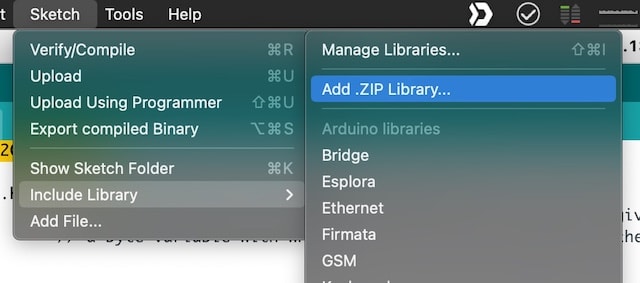
The library should now be listed in that same menu and can be included in the sketch.
In the introduction there are these daunting words:
Also, I wanted to emphasize that these routines don't follow the Arduino Wire library naming conventions. In addition, these routines differ from the Tiny Wire library routines.
This probably translates to another few rounds of internet searches...
I decide to start with the examples listed on the github page. The first bing the Port scanner. This can be a handy tool to use in any way as it helps you to find other stuff on the network.
Compiling the code creates some errors:
In function 'void setup()': TinyPortScanner:3:6: error: redefinition of 'void setup()'
It turns out that you shouldn't use tabs in the Arduino app...
An assumption is that tabs are for new sketches. But they only open another file for some more code; for the same sketch. Meaning you only declare void setup() and void loop() once. So you may have declared this more than once leading to this error.
Creating a new window and placing the sketch there works. The code is uploading and when I then switch to the serial port and set the baud rate to 9600 I can see that my board is scanning. \o/
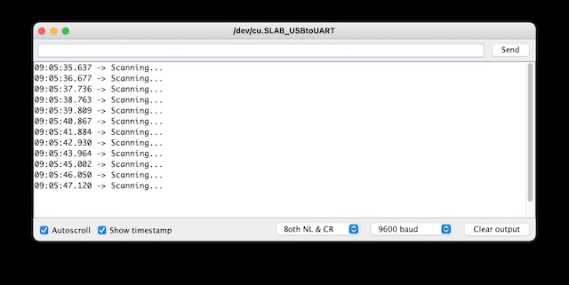
It is not finding anything, but that was to be expected. Attiny412 has no I2C address by itself. I need to set that. But how...? There is no reference in the TinyMegaI2C readme to using the library for student nodes... So maybe I can just use the same library for both teachers and student nodes...?
I will try to use the earlier code from the instructables page and use the readme of TinyMegaI2C to see I can can come to a working sketch.
Rewiring
In the meantime it seems that the hardware of my boards is not correct as well. Even tough I checked the boards last week with Henk and he then said that the boards were good, he now claims that I need resistors between SCL, SDA and VCC and that without these it isn't going to work.
He also says that the TinyMegaI2C library is well documented enough to get stuff to work. So my current to do list is:
- Rewire the boards and add some resistors somewhere
- try to understand the TinyMegaI2C library to such a level that it becomes usefull to me.
- Try at least one more time to check if the wire.h library is really too big.
As there is not really any time left this week I will have to postpone these actions to some later date.
When, and if, I continue with that, here are some relevant starting points:
- An nice I2C summary
- Phils docs in which he details the same resistor issues
- Danielle of Lintfort recorded his class explaining networking and communications
Continued work on the board.
Weeks later I am finally back in a position where I can look at these boards. I am happy that past-me took the time to write down where the process stalled. This way I can pick up the bat easy enough.
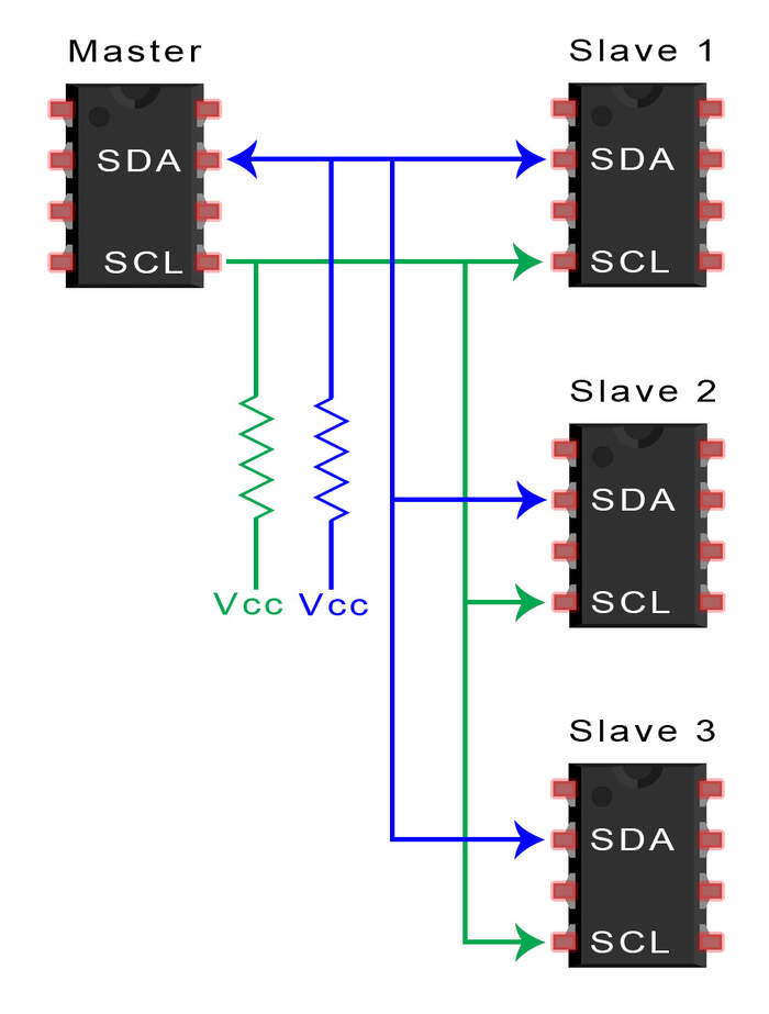
adding a pull-up resitor
"SCL is for the clock signal, and the SDA is for the data signal. Both the SCL and SDA lines are "open drain" drivers. What this means is that the chip can drive its output low, but cannot drive it high. For the line to be able to go high you must provide pull-up resistors to the 5V supply. You only need one set of pull-up resistors for the whole I2C bus and not for each device. If the resistor are missing, the SCL and SDA lines will always be low - nearly 0 volts - and the I2C bus will not work." ~ source
Checking multiple links to Fabacademy documentation, I find that forgetting the pull-up resistor is nothing to be ashamed of. It happens all the time to everyone.
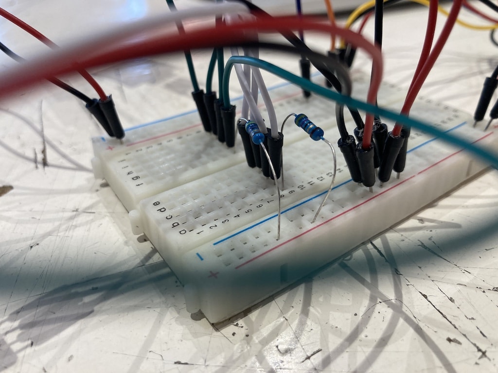
I added mine on the bread board following the advice above: "You only need one set of pull-up resistors for the whole I2C bus and not for each device.". Also, When I check Paulas documentation I see that the resistors can be on the bus. and don't need to be on the board.
Mine are now here:
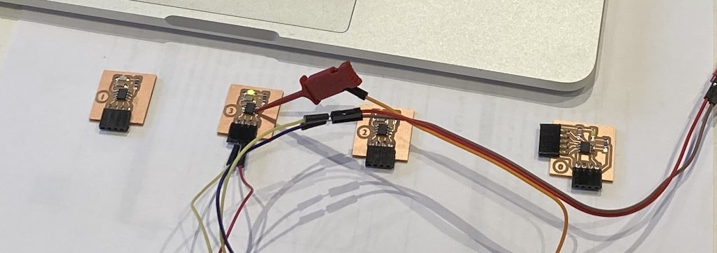
Making the net-work
And while we are at it, we might as well look at the entire network:
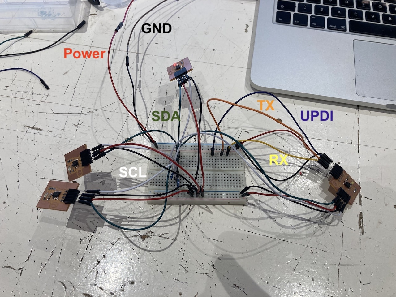
It is not hard to understand why some people, like Neil, hate breadboards when you see this mess... Anyway, I tried to make it as tidy as possible and at least colour coordinated the wires.
- Red: Power
- Black: GND
- Blue: UPDI
- Orange: TX
- Yellow: RX
- Green: SDA
- White: SCL
Programming the board.
Following the examples of other students online, I think the save way is to use the TinyWire libraries after all (see my search above).
This Tiny85_Temp example shows that the I2C library must be initialized in the setup function. Then, sending a byte is done with "beginTransmission()" specifying the destination address, "send()" for sending the data, and finally "endTransmission()" closes the transmission.
And I run into error mayhem landscape again. I am getting so tired of this... I try left and right to change, uncomment and amend things, but problems stay.
At least I try the inlcuded TinyWireM again; same problem; more error spaghetti. And then I decide to try to wire library again. And that works. zoink. Why? I have no idea. But the code compiles with a lovely message saying:
Sketch uses 2120 bytes (51%) of program storage space. Maximum is 4096 bytes.
So there is suddenly even more then halve of the space left, even when using the wire library.. Oh well. With this we can work.
I make a program that blinks the master board. Together with the first blink, the first student board also blinks. With the second blink the second student board blinks along and with the third blink... you get it.
Using the tiny clamp Henk gave me I can upload the code to the students boards like I did when just testing their LED's. And low and behold, everything works! Maybe I should always not look at a project for several weeks before picking it up again...
You can find the teacher code here. And you can find the student code here
NOTE for the student code you have to change the device address everytime before uploading. Otherwise they have all the same address.
Research and relevant links
- https://www.instructables.com/ATTiny-USI-I2C-The-detailed-in-depth-and-infor/
- http://academy.cba.mit.edu/classes/networking_communications/I2C/hello.I2C.ino
- https://www.arduino.cc/en/reference/wire
- https://www.avrfreaks.net/forum/how-decide-i2c-address
- https://www.instructables.com/Arduino-I2C-and-Multiple-Slaves/
- http://www.technoblogy.com/show?2QYB
- https://www.youtube.com/watch?v=4hqy40y-dlE&feature=emb_logo
What went wrong and what should've been done different?
- Design more carefully. It is hard to find the optimum between a design that you can think is good enough and the extra thought-loop that was needed to make it really good. Do you release early and use the extra time you gained to correct errors you encounter later? Or do you release slowly and prevent errors from occuring in the first place? This week shows that the latter option is better.
- libraries can be usefull, but also annoying. Be sure to check carefully what you want to do with a library and if it really (not) fits on your MCU.