Group assignment
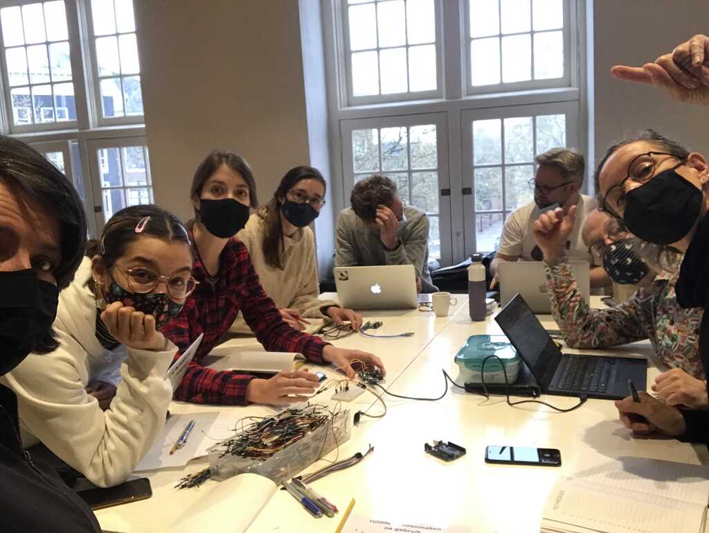
This time we decided to form one big group and not split in parts.
The group assignment consisted of two parts.
- Connect multiple inputs or outputs to one i2c bus.
- Connect two or more project-boards together and make an addressable network.
Playing with i2c
Before lunch we worked on the i2c.
i2c (inter-integrated-circuit) is a serial bus meant for connecting various integrated circuits together within one apparatus. Philips originally invented this for connecting various components in consumer electronic devices. It has now become a standard for connecting input and output devices to microcontrollers.
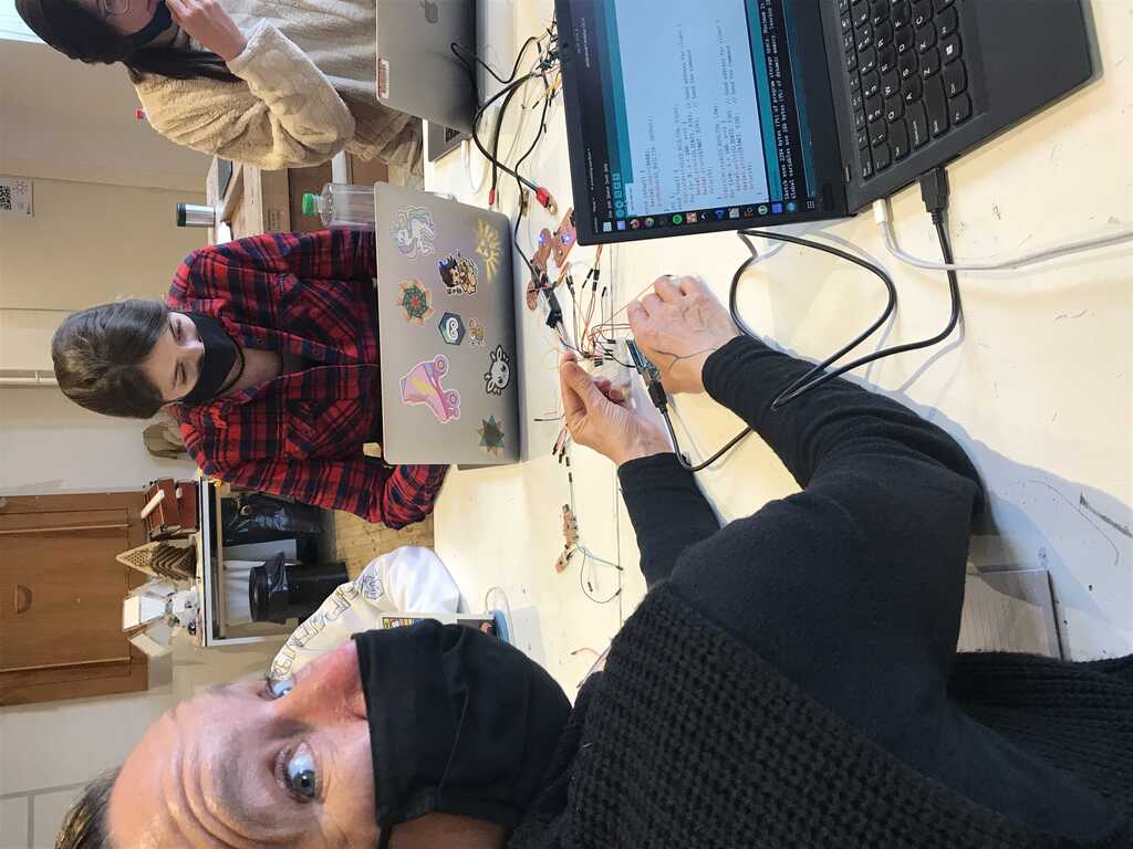
We used a ready-made Arduino Leonardo board as controller and a breadboard to connect every component together.
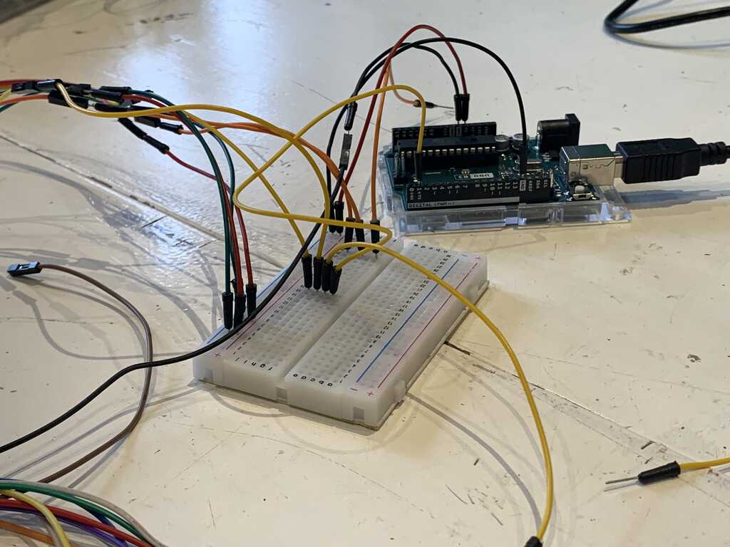
We connected a LCD display with a hdd44780 controller and i2c daughter board to it. The daughter board takes care of setting the correct signals on the parallel interface of the HD44780 display. Normally it would require at least 7 pins (+ power) to connect this display to a microcontroller, now only two (+ power) suffice.
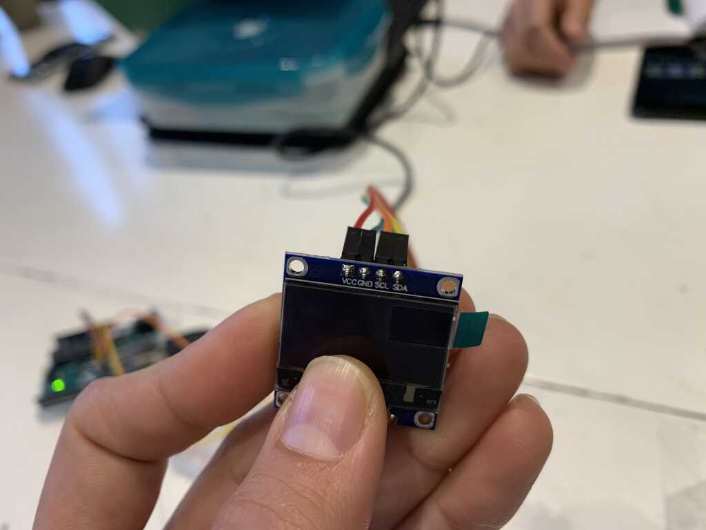
We also connected an OLED display with SDD1306 controller.
It is a good practice to pick a color-scheme when connecting microprocessors. For this circuit we used:
- - Ground -> Green
- - VCC -> Red
- - SCL -> Orange
- - SDA -> Yellow
First we needed to determine the i2c addresses of the different components. For this we made a simple i2c address scanner. The source code can be found in the section "Project files" below.
The scanner simply sends out an address and checks if there is a response. If there is a response, then there is a device.
The scanner scanned from address 0 to 255. This gave double the amount of devices. The addresses can be seen in this picture.
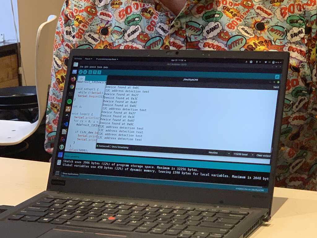
Turns out i2c addresses only go from 0 to 127, so the scanner finds a device on 0x27 and 0xA7. 0xA7 - 0x27 = 0x80 (127 decimal), so the device responds to the lower 7 bits. When the scanner scans the address with the highest bit also set, the device thinks it has to respond.
In the end we adjusted the scanner to only scan from 0 to 127 and we found the two connected displays on 0x27 (hd44780) and 0x3c (ssd1306).
hd44780 display
The hd44780 display is a 16x2 LCD with onboard character generator. This means you can tell it to display character 0x31 and it will display a "1".
We used the Adafruit hd44780 library for the display.
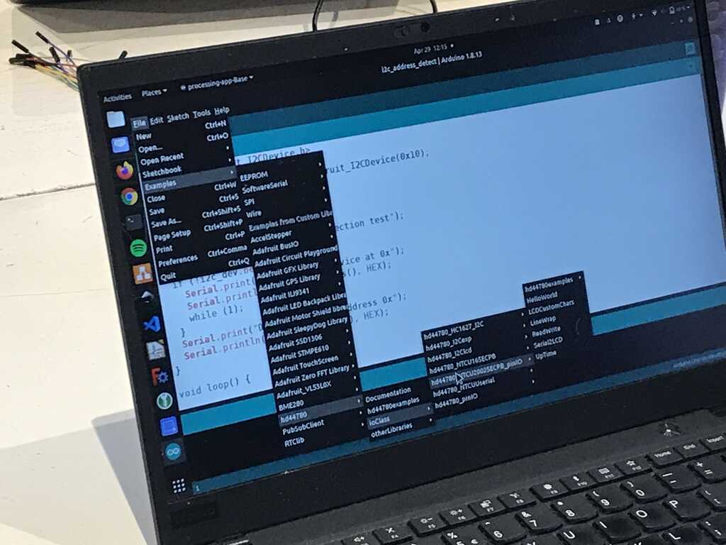
The source code can be found in the section "Project files" below.
After specifying the correct address and an interesting text, the text was displayed on the LCD.
ssd1306 display
The ssd1306 display is a 128x32 OLED display. The characters and graphics need to be created by the host microcontroller and send to the display. This requires much more communication.
We used the Adafruit ssd1306 library for the display.
The source code can be found in the section "Project files" below.
After specifying the correct address, the demo included in the library started.
Putting it all together
The assignment was connecting two devices to the same bus, so we integrated the displays.
When connecting multiple devices, the libraries can sometimes cause conflicts when trying to control the communication bus. Because we used both libraries from the same vendor (AdaFruit), this was not a problem.
The code was modified to have the LCD display the effect that the OLED display is showing.
< tada.wav >
The source code can be found in the section "Project files" below.
Playing with serial
After lunch we continued with serial (UART) communication.
With i2c there are pre-defined addresses. But now we have to make our own protocol with its own addresses.
The protocol is very simple: 1 byte address and 1 byte data.
Clients will receive the address, check to see if it is theirs and process the data if they are addressed.
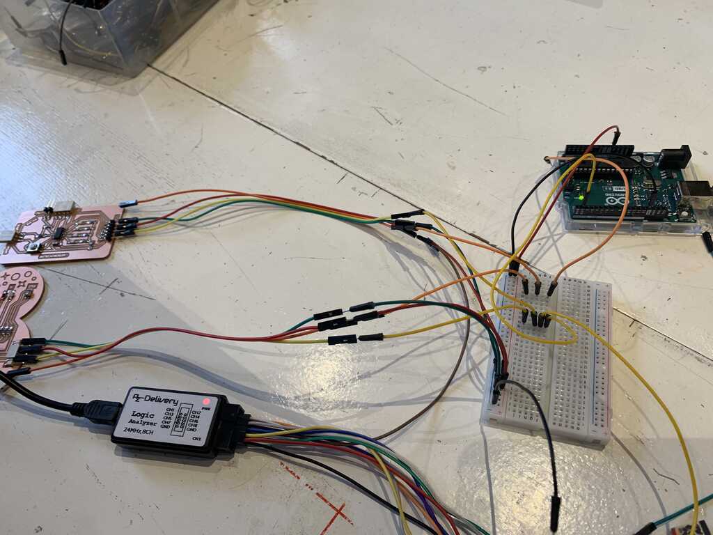
We have the same Arduino Leonardo as the host and two FabAcademy boards (by Nadieh and Nicole) as clients connected through the breadboard.
We need three three pieces of code: one for the host, one for Nadieh's board with address 1 and one for Nicole's board with address 2.
We are going to keep things simple by only sending information from the host to the clients, not the other way around.
All board need to speak at the same speed, so all boards are configured for 9600 baud, with 8,n,1 (8 bits, no parity and 1 stop bit).
Host
The host program is very simple. It sends address=1/data=1 and address=2/data=1.
The source code can be found in the section "Project files" below.
Important with the Arduino: When programming it, disconnect the serial lines to the breadboard. The programming RX/TX lines are the same RX/TX lines used for the serial communication and the connected boards interfere with the programming.
Clients
The clients need to do a bit more work.
If an address arrives, it checks to see if it is its address. If yes, then it saves the data. If not, then it discards the data.
To check various parts of the communication, multiple leds were used to define the states
- Somebody's address received
- My address received
- Data received
The source code can be found in the section "Project files" below.
Putting it all together
Now we connect the TX line of the host to the RX lines of the clients and...
It's not working as expected.
In order to troubleshoot, we connect a logic analyzer and inspect the signals.
The clients are expecting address 1 and 2, but the host sends 31 and 32...
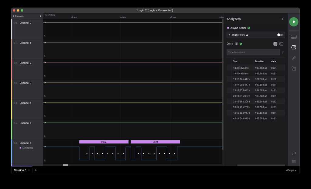
31 is the hexadecimal representation of the character "1" and 32 is the hexadecimal representation of the character "2".
Changing the host's code to explicitly send binary (by specifying 0b00000001) did not change its behaviour.
After changing the addresses of the clients to 31 and 32, it works like a charm and the host can address the individual clients.
In hindsight
Erwin decided to recreate the setup at home and continued troubleshooting.
Turns out that the Serial.print(); function converts values to their hexadecimal character value. So Serial.print(1); becomes 0x31. Using Serial.write(); will send the value exactly exactly as it is. So Serial.write(1); becomes 0x01.
Project files
The source code of the i2c scanner can be found here.
The source code of the i2c hd44780 display can be found here.
The source code of the i2c ssd1306 display can be found here.
The source code of the combined i2c displays can be found here.
The source code of the serial host can be found here.
The source code of the serial clients can be found here.