Computer-Aided Design
openscad is great for parametric parts, but you will go insane programming things such as bevels and stuff
Description
Model (raster, vector, 2D, 3D, render, animate, simulate, ...) a possible final project, compress your images and videos, and post it on your website.
This week I am going to make as many mockups as I can, using different 2D and 3D programs. My initial sketch was made on an ereader. It is time to take it to the next level!
Assignments - Learning Outcomes
| # | Assignment | Fin |
|---|---|---|
| 1 | Evaluate and select 2D and 3D software | 1 |
| 2 | Demonstrate and describe processes used in modelling with 2D and 3D software | 1 |
Spirals - Have you?
| Spirals | Description | Done |
|---|---|---|
| A | Modelled experimental objects/part of a possible project in 2D and 3D software | 1 |
| B | Shown how you did it with words/images/screenshots | 1 |
| C | Included your original design files | 1 |
#1. Evaluate and select 2D and 3D software
Adobe Illustrator
To make it a little bit easier on myself I am first going to make a sketch in a program I know really well. This will allow me to be more creative and less frustrated. This basic model I can then use to recreate in other programs.
Installing
This was easy using the Adobe installer. And I already had the program... so...
I made a drawing of the model as I think it should be. As colours are important, and I drew inspiration from the '80 synth TR-808, I pasted a picture of that synth in my file. I then traced the bitmap image so I could easily extract colour from it.
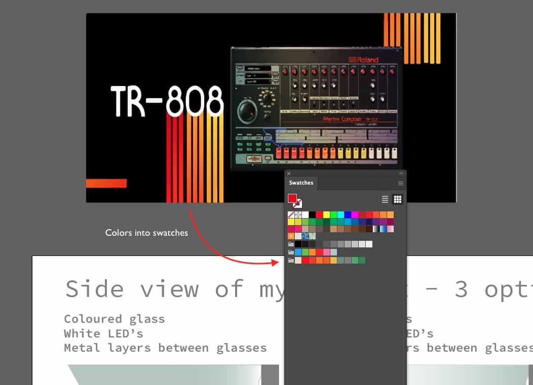
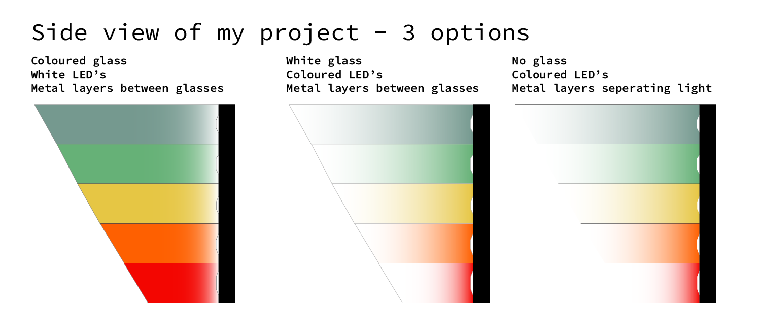
I played with different options to make this clock. The three options I consider can be seen in the illustrator file.
You can download the original file here
Photoshop
Installing
Photoshop was already on my machine so that was easy.
Mockup
I made a picture of where I want my machine to be in the house (next to my front door) and added the file I made in Fusion360 to it to get an idea of how it might look in real life
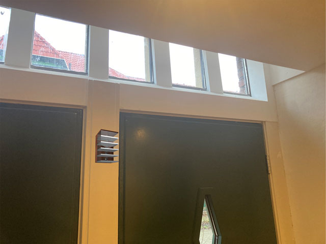
The original design file is over 8MB and I am not going to waste my precious repo space on that. After all, it is a picture with a render placed in it. These two steps are not worth to document other then by words. Which I have now done.
Fusion360
Research into F360 was done with the help from:
- a youtube playlist
- a lesson by Agrilab
- And another lesson by Michelle.
I think I am now ready to plunge in. I have a slightly new idea for my final project, so I will use Fusion360 to show you what it is. But to give you a head start
- The model is more horizontal then vertical now (so it can fit above my front door)
- The model should get a nice 80's electronics feeling to it. Think [Roland TR-808] color scheme.

- I want to achieve color by filters, not color by LED's. All LED's should be white.
Installing
Installing was a breeze thnx to the license we got with our education. I am now gonna use this to make my first drawing.
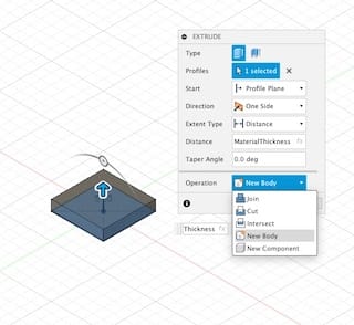
Getting a box
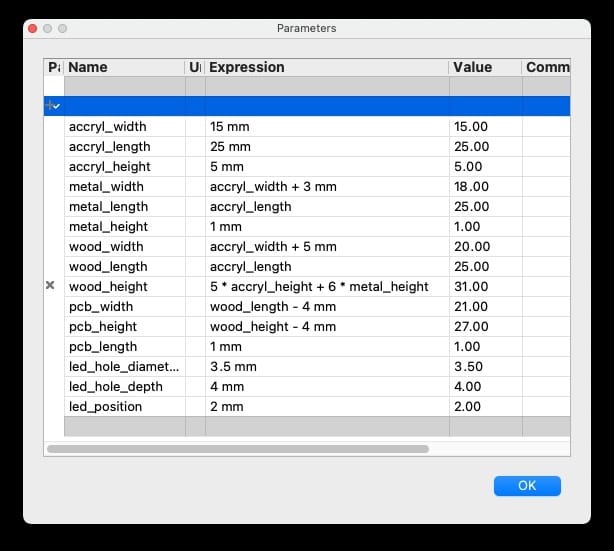
I start by filling out the parameters.
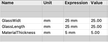
NOTE: if you make mistakes, and you 'undo' using ctrl-z, the changes you made in the parameters panel are also undone.
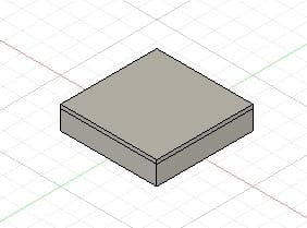
Et voila, a new body has been created.
Getting a sheet of metal on the box
I have created a new sketch. This will represent a sheet of metal. I want the sheet of metal on the box. The main problem here was getting selecting the metal (which was resolved by hiding the other body in front of it) The other problem was lifting it, but this was resolved with the move command.
look! there is a thin layer of pure aluminum on top!
Current frustrations
- copy-paste is not so easy: if I select something, and use cmd-c and cmd-v nothing happens.
- I need to change the functions of my pen to be able to use it with Fusion360. But changing the pen is really annoying because I am so used to it to work in a certain way.
- I am not used to thinking in 3D on a computer... My designs are always 2D. I get lost in space.
- Feeling frustrated and tired. Gonna take a break.
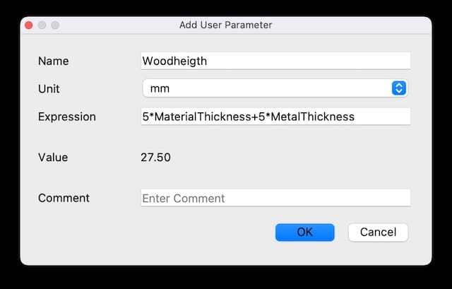
Parameters are cool
Parameters are for 3D objects, what paragraph styles are for text Playing with the parameters brought me a lot. It is a nice, reassuring feeling I can modify stuff in one place and have it changed everywhere. I even experimented a little with parameters in parameters.
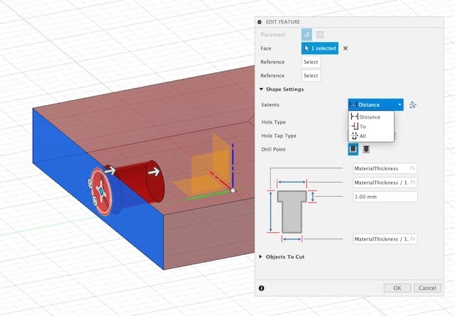
Adding a little hole.
I was looking and think how to make a little hole in the back of the acrylic pane. But when I right-clicked, Fusion offered me the 'hole feature..
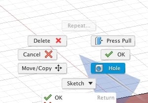
Using this feature I made a tiny little hole in the back, that I will hope will fit a LED. But if not, no worries; I used all parametric numbers, so I can easily change them when needed. Woohoo!
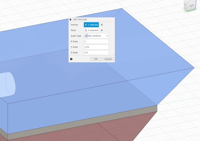
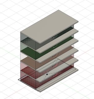
Multiplying a part.
Now I want to get multiple parts of the little thingy I made. Every part should be 5mm longer and on top of the previous one.
Using copy paste on the body I wanted to duplicate, I was able to create a new body. I could also move that on top of the existing body. But now come the resizing. I am using the scaling option from the 'Modify' tools. But this does not feel correct. It will destroy the parametric qualities of my design...
I think I'll have to duplicate my sketch, not the body. And create a new body from that new sketch... Let's try that.
Copying the sketch did work and I can now edit the sketch. The problem is that certain properties need to be applied again: the colour and the hole in the back are not copied over.
I should try to find a 'best of both worlds'.
After some testing it seems that copying bodies is the better way to go.
Getting some colour.
I find that colour, material and texture are very important in my design. You can add a material to a body by dragging it from the material window on the body. After that you can change the appearance in the appearance menu.
I'll extract the RGB values from my illustrator file and put them here for all to remember
| HEX | #75998F | #66B177 | #E6C644 | #FE6001 | #F30601 |
| RGB | R:117 G:153 B:143 | R:102 G:177 B:119 | R:230 G:198 B:68 | R:254 G:96 B:1 | R:243 G:6 B:1 |

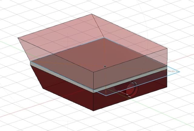
Copy/paste bodies and destroy aspiration
Although I think Fusion360 is the most user friendly 3D design tool out there, it still poses me with a lot of challenges. But I am currently left with this:
And the most important things I learned are: - set parameters as you go; new stuff comes up when you draw, and whenever you can use the parameters to define the dimensions - you can make a hole and the parameters for its dimensions - you can use the move tool to make copies of bodies. - in my case it seems best to do the chamfers áfter I made the initial design. On the other hand I am no longer sure if I should do them at all; maybe a more cubic design is better to mimic an '80's design. - I am still unsure how to use the sketches. Shall I make one for every body, or can I use one sketch for all similar bodies. - How come I have now multiple bodies on my drawing and only three sketches... ?
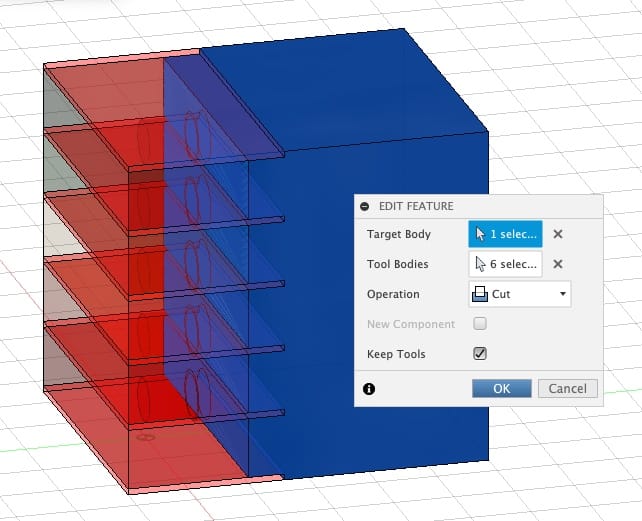
Cuts
The structure I have made has little alu parts extruding it on the back. These should be cut out of a body of wood so that everything slides snugly into place.
For this I used the combine tool and a little video tutorial I found.
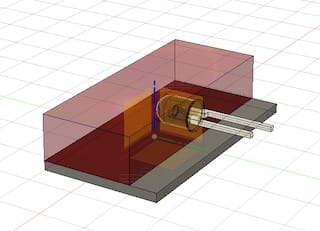
Making a hole and a PCB (part 2)
Using the Shell option I made the wooden box hollow. After that I created (my first) sketch on a different plane. This Sketch should become the PCB with the LED's.
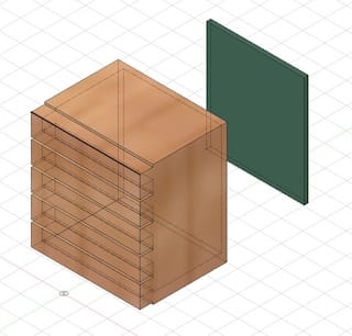
NOTE: Later Michelle told me that I can better use the extract function to cut away a hole. In this way I an make a sketch, which I an align with other object, and apply parameters. This keeps the parametric quality of the design and reduces random shit
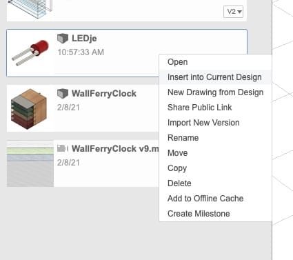
using an external model
For the LED's i searched online and found a model that I could use on GrabCad. The legs of a model are too long, but this is something I will solve in another spiral.
I copy-pasted the LED into my design from another file.
NOTE: Fusion360 doesn't open .STP files by itself. You have to force to open it by dragging the file onto the application in the dock while holding the ctrl-command. This forces a program (on mac) to try to open the file. And it works.
NOTE 2: It is better to open a file in a different tab, save that tab and insert the object from the Datapanel
Current state is:
(this video did not work immediately. I document why not and how I solved it in week1 assignment page )
Making an exploded view.
In the animation workbench of Fusion360 you can attempt to make an animation. Following good practices, your model should be able to nicely 'explode' in this view. I find it very hard. This is probably because I did not construct my model in the right way.
Michelle talks
After a brief one-on-one session with Michelle I decided to do the design again. Biggest reasons are:
- my design has a lot of repetition. Most of these I drew by hand. Therefore it is not parametric and things get messy.
- There is nice options in F360 to make repetition automated. This gives me an opportunity to practice with that.
- Instead of making stuff even more messy by trying to adjust my existing design, it is better to start again; I will also learn more from starting a new.
New beginnings
This time I made a base component structure that I am going to repeat. It exists out of
- an acrylic box
- a metal sheet
- a hole in the acrylic box
- a LED imported design
In order to multiply this object, I merged the items together in one component. I then used the Pattern on Path function to multiply the selection above the original form. This created a rather unexpected glitchy effect.
Newer Beginnings
In order to make fewer mistakes, I am now going to follow a path that Michelle layed out for me.
Steps in this order;
- Create parameters.
- Make sure parameters reference each other where possible.
- Stay parametric in your design! Also when you think you can't, you can.
- Use the same sketch to make multiple bodies.
- Use the Pattern on Path option to create multiple copies of a body.
All went fine so far.
The main problem now is that I have linked bodies (because of step 5) and when I change color of one, they all change. I need to unlink this somehow...
For now this is the end of the design-process. I hope I can continue and apply what I have learned so far to designs that are meant to be cut or printed by real machines soon.
Renderings
Images
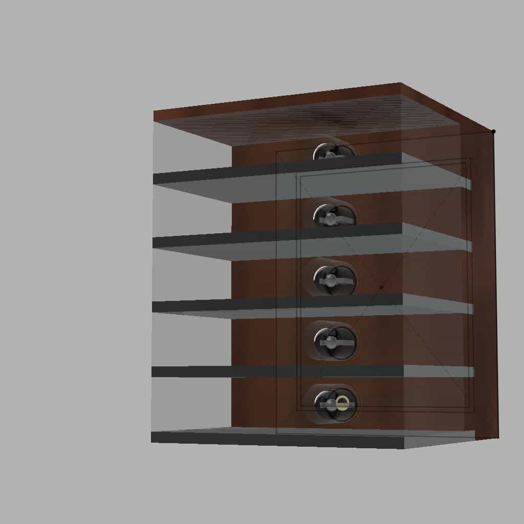
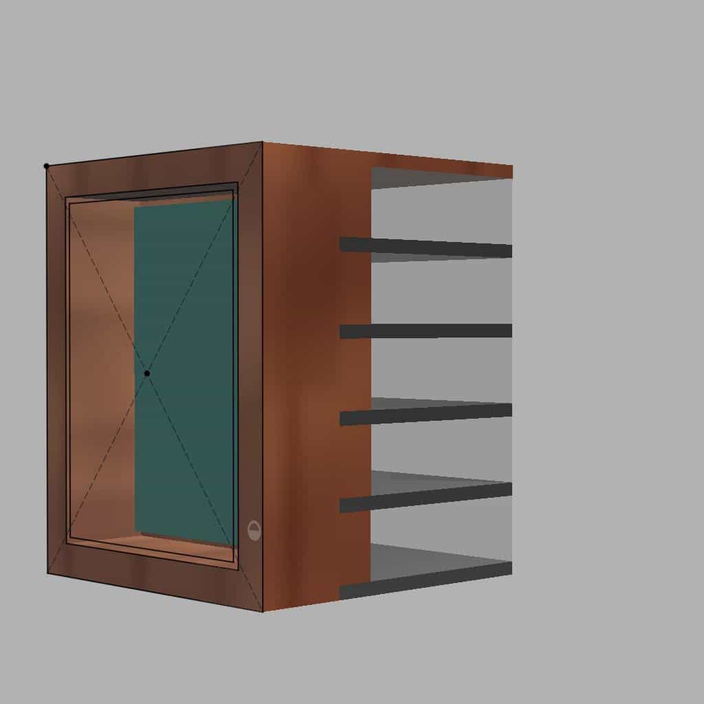
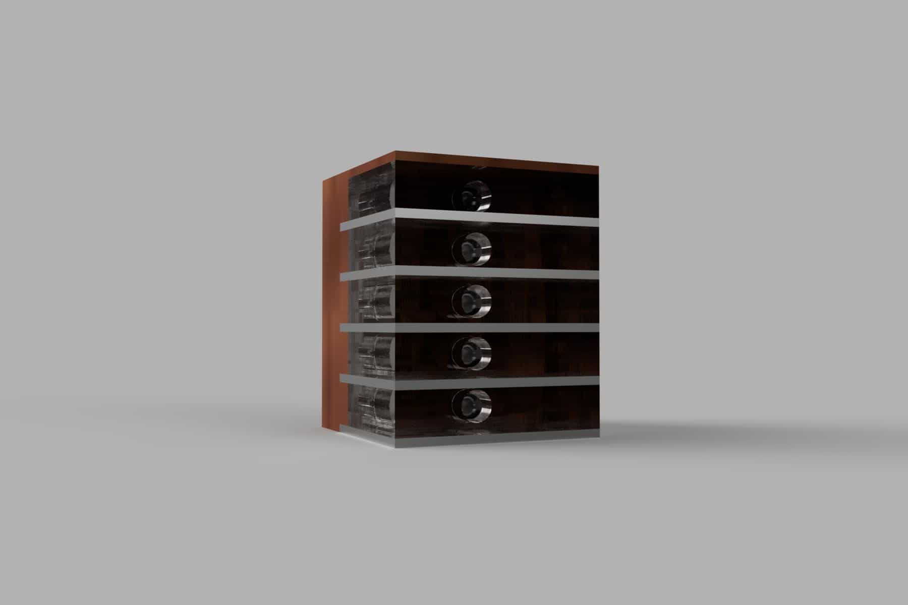
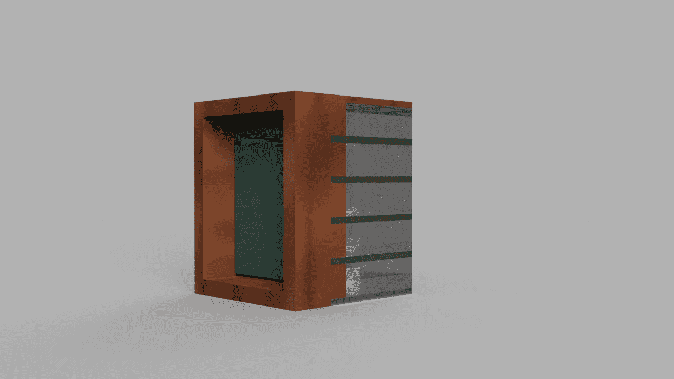
*Note: I am not so happy with the Fusion360 renderings. The actual, unrendered model represents better what I intend to make, then the rendered image...
Video
Other Software
Freecad
Following this tutorial https://drvax.com/freecad-pre-releases-on-macos/
Installing the latest version on Big Sur creates issues. The mentioned article details how FreeCAD can be installed despite this. So... let's try!
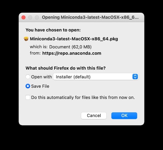
The FreeCad developers package the current macOS pre-releases with Conda. It is easy to install MiniConda on your Mac and use it to install FreeCad.
MiniConda interlude
As these things go in OpenSource world, before you can do what you want to do, you first have to do something else. Some call it yak-shaving. But apparently FreeCAD requires Conda. Which has a tiny little brother for Mac, called miniconda. Let's get and install that.
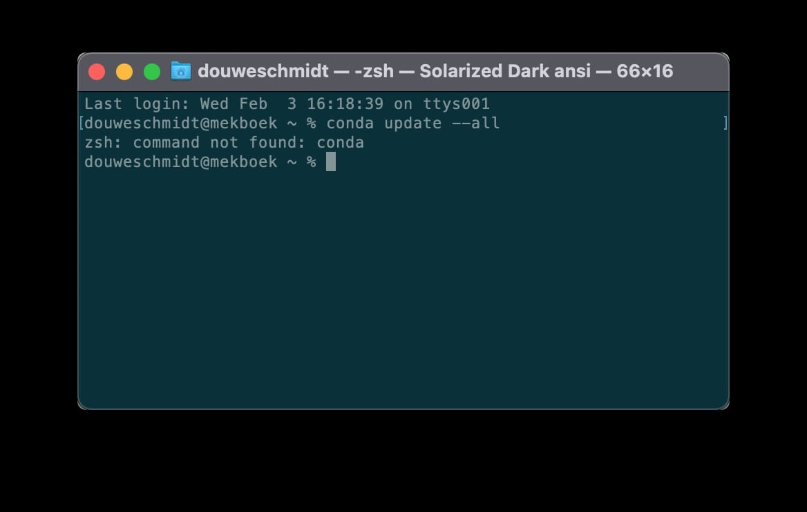
After that is that we are going to do some terminal work.
$ conda update --all
$ conda create --name fcenv --channel conda-forge freecad
Or... so we hoped...
Time to insert a debuggin table...
| Problem | Description | Debugging | Solved |
|---|---|---|---|
| Can't update Conda from command line | command not found | log-out and relogin and try with sudo | 0 |
| idem | idem | install conda with pip | 0 |
| idem | idem | uninstall conda, miniconda and the whole shebang | 1 |
Result
I gave up on installing Freecad. Otherwise there is no time left to make an actual model.
OpenSCAD
Installing
$ pip install openscad
You then find the app in the application folder.
Result
I gave up on using OpenSCAD. Otherwise there is no time left to make an actual model.
What went wrong
- Not enough time to explore all the programs that I wanted. In the end I decided it was more important to get to a design that at least somewhat resembled what I wanted to make, then getting to know all the programs.
-
Fusion360 was much harder then I anticipated. Even with the help of Michelle and numerous Youtube videos I spend way more time on this program than I anticipated.
- I need to learn more about constraints and joints.
- I was not ready for exporting in exploded view.
-
My spirals and time budget planning as projected in the beginning were not met. I need to take more time to plan the week ahead. (For my defence; sudden school closings due to global pandamics do not help...)
- Also I keep forgetting that I am really tired in the evenings. So it is hard to use the time I imagine I have there.
- 3D modelling is really a different beast. I keep forgetting to remember to forget all I learned in 2D design.