Input Devices
A note upfront
While very interesting and entertaining, my notes below do not lead you to a succesful input device week. Only two weeks later, in output devices week, I was able to get it all working. Follow the page there for more succes. If, on the other hand you enjoy reading more about failures, you have come to the right place my friend.
Description
This week we learn how to get data into a device. As I have been extensively testing BLE input and BLR input last two week for the Machine week, I hope to be able to expand on that. Especially the 'step response' seems interesting as it makes the sensor making really playful.
Progress can be checked in Nueval.
From this week onwards I keep the checklist for what I have done in the assessment page of Fabacademy. You can find that here.
NOTE added on June 15 Older and wiser me found that keeping a checklist on a separate page does not work; I never looked at the checklist and nueval again. So for future projects: keep things as close to each other as possible, otherwise you won't use them...
Essential Henk Notes on Input Devices
For this week you need to use the inventory page of the fabacademy
From row 578 onwards you can see all the small electronics parts we get from digikey. The names on the sheet are sometimes to long to put on the boxes in the electronics corner. Lucia made an overview of where is which.
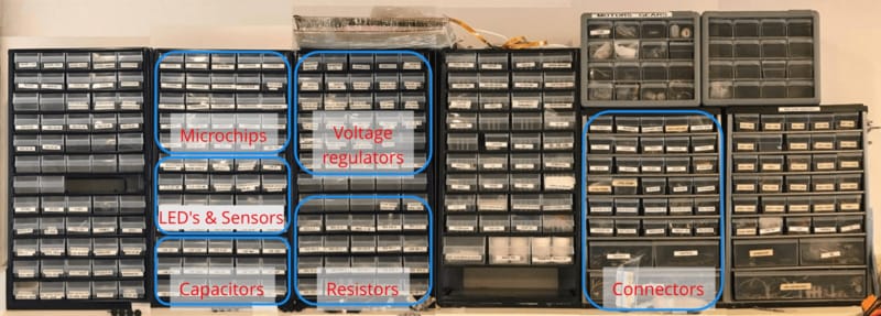
Henk pleads to keep any labels that are inside the boxes to remain there. He needs these.
Input devices
- Most of the notes about clocks are no longer relevant: the modern ATTinyes have accurate clocks on board. This has made life easier for everyone.
- Almost all sensors are based on resistors: a change in sensing means a change in resistance.
Stuff I should do:
- See what sensor(s) makes sense for me to use.
- Check the board I can use/modify to attach to it.
- make the board
- analyse it and use it
Sensors I want to try at least in order of need:
- movement (doppler)
- magnetic field
- temperature
- BLE
Stuff that worries me the most is power; how do you know which resistor goes where? How do you know if it is 5v or 3.3v? When asking Henk he said that basically you don't calculate this yourself at start. You let KiCad do it, or you just look at examples and do what they did.
Assignment 1
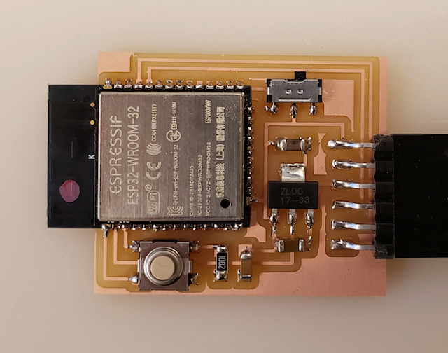
We have to measure signals on a board we made ourselves. As the HelloWorld board was made by Henk, and we just copied what he did, I have to make myself a new board. I use the files from the networking week of Neil. In that week he talks about the ESP32. And there are some drawings and pictures in there how he connected the controller to his own PCB instead of using a ready made breakout board.
In his example the number of pins that you can still access is really limited. Probably because he is mainly interested in the networking part of the board and the wireless parts don't need pins.
So I use his board as a basic and will create a row of pins on one side of the board to easily plug and play with the pins on controller.
The start - redoing what is already done in KiCad.
Using Neil's drawing and picture I recreate his board in KiCad. But... I got tired of trying to recreate what Neil already made and decided that there is actually an easier way to achieve what I need. As the assignment was to make your own board, I did just that. I skipped KiCad and modified the files of Neil in Illustrator...
I figured I just needed to breakout some pins, and if I could make some room on Neil's board, I could add the pins there.
I kinda like the very basic way of drawing something that will conduct electricity later on.
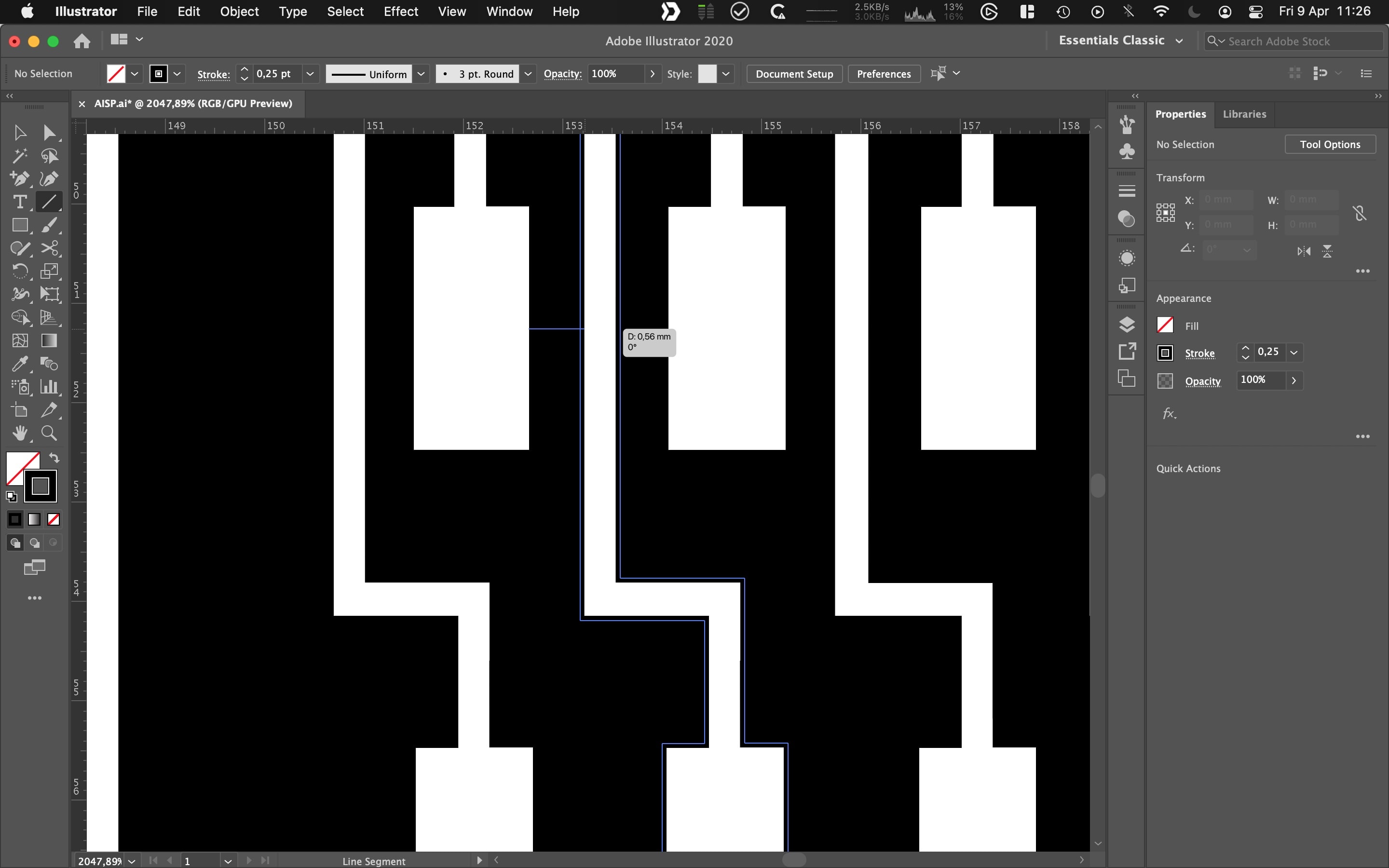
You do have to mind the paths and that they don't become to narrow for the mill...
So this:
Became this:
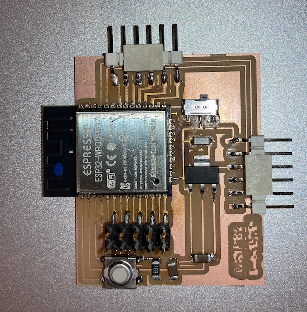
Board has been milled. Board has been stuffed. Board is not working. Debugging table is needed.
Debugging the board, round 1.
| # | Problem | Hypotheses | Debugging + errors | Solved |
|---|---|---|---|---|
| 1 | Board is not responding to my tests | Tx and Rx wires are wrong | Try them in reverse and see what happens - termios.error: (22, 'Invalid argument') - Failed to execute script esptool the selected serial port Failed to execute script esptool does not exist or your board is not connected |
0 |
| 2 | idem | there is a slide switch on the board. maybe the board is off | try both positions. Also check with video neil. | 0 |
| 3 | idem | the soldering went wrong and some traces are not working so I should use an volt meter to check traces and soldering | Indeed the soldering of the switch button was not good, but repairing it did not solve the issue | 0 |
| 4 | idem | idem | it seems that rxo is also not soldered correctly | lets try to put some extra solder there. |
| 5 | idem | maybe I should attach the board without a USB hub to my computer | that gave a new error: A fatal error occurred: Failed to connect to ESP32: Timed out waiting for packet header |
0 |
| 6 | idem | let's try step 1 again | I get the notification that Chip is ESP32-D0WDQ6 (revision 1) is found |
1 |
This is the correct way to attach RX and TX:
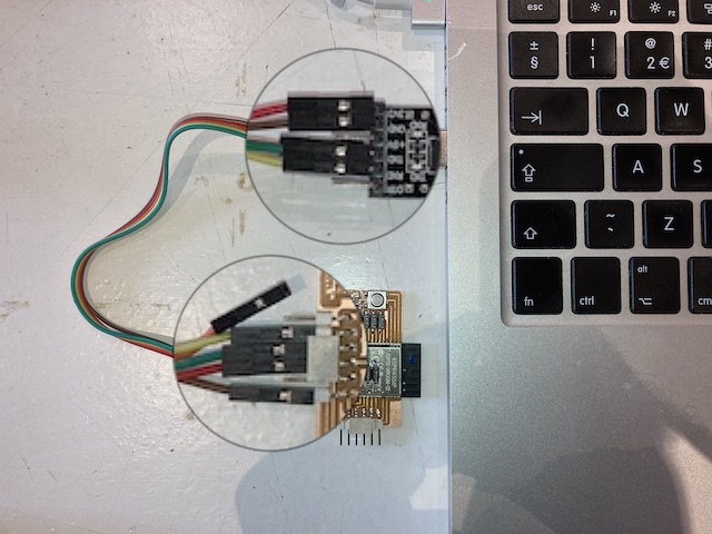
So success! The board is found!
Now I need to workout all the pins so I can attach external sensors for this weeks assignment.
Add extra GND pins.
The board I made has at least one flaw I quickly discovered: no GND pin exposed. As all devices need to be connected to GND it would have been very helpfull to have at least one available on the board. While doing my debugging I found that the metal house, or shield, of the ESP32 microcontroller is also attached to ground. So there is a huge piece of metal that has what I need right in the middle of the board.
What if... I soldered some pins to that...?
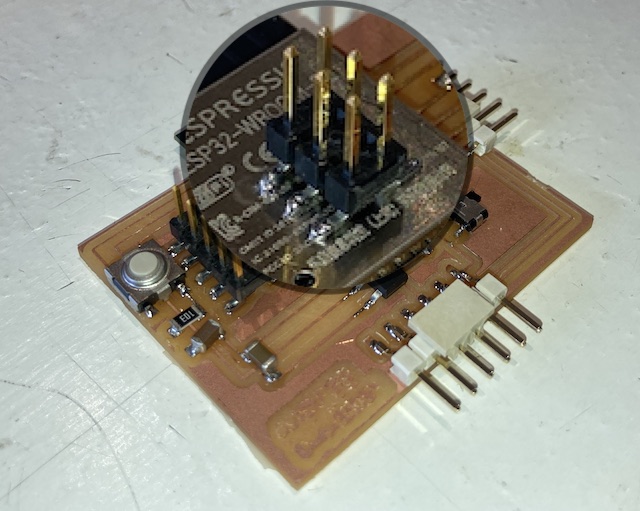
I feel that there is a special place in fablab hell for people like me... 🙊
Now that I have the ESP32 attached to my board and many pins broken out, and I have ground available for any sensor that need it, I now need to map my own pins to the ports so I can use them. For this I will draw a schematic.
Now that the ports are properly mapped, I can have lunch.
After my breadroll I make an attempt to get the signal of an Arduino Sensor Kit Microphone into my AiSP32 board. For this I found a very nice and detailed tutorial.
int sound_digital = 28;
int sound_analog = 6;

void setup(){
  Serial.begin(9600);
  pinMode(sound_digital, INPUT);
}

void loop(){
  int val_digital = digitalRead(sound_digital);
  int val_analog = analogRead(sound_analog);

  Serial.print(val_analog);
  Serial.print("\t");
  Serial.println(val_digital);

  if (val_digital == HIGH)
  {
    Serial.println("sound");

    delay(3000);
    }
  else
  {
    Serial.println("no sound");

    }
}
Due to my weird, non-conventional board, I have to think at least three times to which pin I have to connect which wire. The uploading of the code seems to be going well, but there is no signal coming in... Debugging table time!
Debugging the board, round 2.
| # | Problem | Hypotheses | Debugging | Solved |
|---|---|---|---|---|
| 1 | There is no serial output in my ArduinoIDE | The pins are not correctly programmed/connected | Try random pins and see what works | 0 |
| 2 | idem | the potentionmeter is killing all signal and should be adjusted | get a small screwdriver and screw away! This did turn of one LED on the board | 0 |
| 3 | idem | idem | don't do this randomly, but think about it. (details below) | 0 |
When doing a more thoughtfull pin connection checking routine I came to the conclusion that I need to do the following steps:
- Check the pin that the sensor is connected to in the tutorial I am using.
- For instance: A0 (the analogue pin) is connected to pin G4.
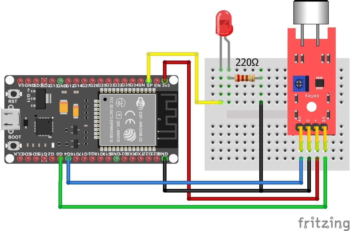
- Check what this port can do and what function is probably used. In this case probably the ADC part.
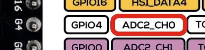
- Check which other ports have similar functions and can be found on my board: like port 25.
- add pin 25 to the code in Arduino as the analogue pin
- connect the wire from A0 on the microphone board to pin25 on the AiSP.
Now for the digital one
- Check the pin that the sensor is connected to in the tutorial I am using.
- The digital pin is conencted to to pin G0
- This pin is already in use on my board. It has a special note in the datasheet that it needs 5V.
- Let's try to see what happens when I connect it to pin 26, which also has a ADC channel.
So far there is no feedback in my serial port from the sound controller. When I press the reset button of the AiSP32 I do get a response in the serial monitor: so the connection is working.
I guess that the pins of the microphone are still not correctly connected. Let's keep our head cool and down and find the problem...
Debugging the board, round 3.
| # | Problem | Hypotheses | Debugging | Solved |
|---|---|---|---|---|
| 4 | There is no serial output in my ArduinoIDE | the program I made has errors | try a simple 'hello world' program to check if that outputs something | 0 |
void setup() {
  Serial.begin(115200);
}

void loop() {
 Serial.print("hello world");
 delay(2000);
}
| # | Problem | Hypotheses | Debugging | Solved |
|---|---|---|---|---|
| 5 | There is no serial output in my ArduinoIDE | the microcontroller is broken | try a complex wifi program from the examples menu and see if that brings up a wifi access point. | 0 |
| 6 | idem | Henk claims that broken microcontrollers seldom happen. So maybe it is a software problem | try serial monitor in Visual Studio Code | 0 |
| 7 | idem | something is wrong with the board | check all the joints and resolder any that might be broken. Indeed I did find some broken joints, but that didn't fix the issue | 0 |
| 8 | idem | not enough power | attach the board to 5v instead of 3.3V | 0 |
| 9 | idem | programmer is broken | try another programmer | 0 |
Current state:
- I can upload sketches to the board
- I get serial feedback when I press the reset button:
14:48:50.582 -> ets Jun  8 2016 00:22:57
14:48:50.582 ->
14:48:50.582 -> rst:0x⸮ets Jun  8 2016 00:22:57
14:48:50.582 ->
14:48:50.582 -> rst:0x1 (POWERON_RESET),boot:0x3 (DOWNLOAD_BOOT(UART0/UART1/SDIO_REI_REO_V2))
14:48:50.616 -> waiting for download
- The 'Hello World' as the 'Blink' test do not give desired results.
- Trying both the wifi and bluetoot examples to activate the bluetooth and Wifi of the ESP32 does not give me a BT module nor wifi access point.
| # | Problem | Hypotheses | Debugging | Solved |
|---|---|---|---|---|
| 10 | idem | the board is faulty afterall | test another ESP32 | 1 |
Using an AZ-delivery ESP32 breakout board I was able to upload any program I wanted. The program is verified to work (SimpleTime) was uploaded using the same method available to me on my own board: using the Tx and Rx pins on the board. And not using the USB that is also available for this on the board.
During the upload, something occurred to me; the board is kind of reluctant to accept new code: you have to press the RST and BOOT buttons several times for some time before it shows the message 'waiting for download' in the terminal, indicating the board is ready to receive the HEX file.
I thought I might need to pay a little closer attention to my board and then I also thought of the switch that is on my AiSP32 board: the one that says prog run in Neils drawing.
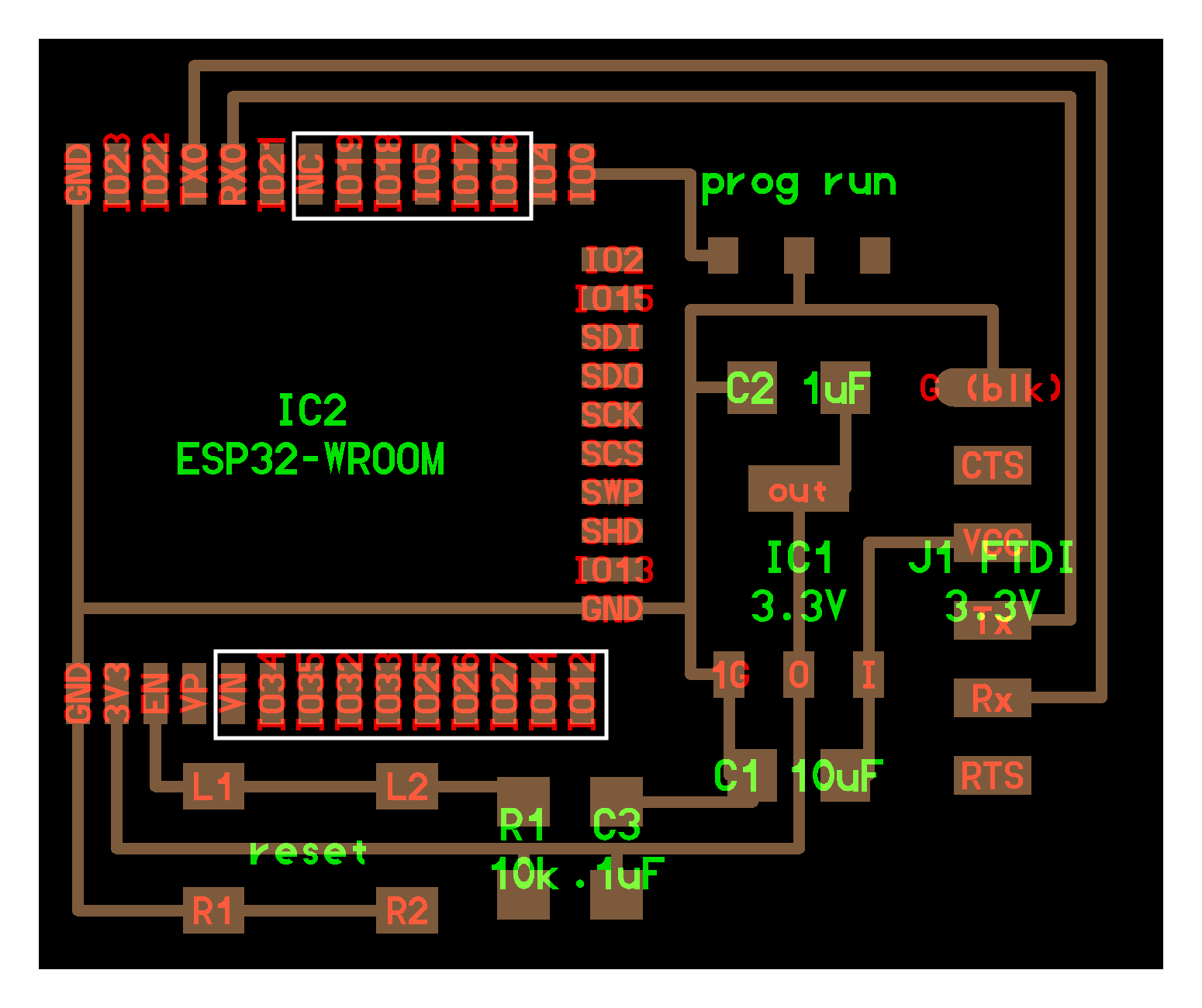
As it turns out, after a little experimenting, the switch functions the change the state of the ESP32 from programmable to run code or something like that. I entirely made those terms up myself... Anyway, what it boils down to is that, in order to upload a sketch, you:
- flick the switch towards the ESP32
- you press the reset button
- you upload your sketch from the IDE
But after you have done that, you have to flick the switch back, and press the rest button again, to run your code. Am I being punished by the microcontroller gods for cutting corners in board development? I guess I am...
upwards and onwards
Now that I have find this 'bug/feature' I can finally program the board and run the program I upload! Or so I thought... Next issue is some kind of kernel panic that happens whenever I try to run an uploaded sketch; no matter if it is a tiny sketch, or a giant one. I get
Guru Meditation Error: Core 0 panic'ed (IllegalInstruction). Exception was unhandled.
After some google work, I find that people say that this error is probably related to an hardware failure... (are you reading along Henk...?) and that maybe a flash wipe can solve this.
So I install ESPtools in Pip using % pip install esptool and then run % esptool.py --chip esp32 erase_flash. Just like with uploading a sketch from an IDE I need to pay attention here that I press the reset button in time.
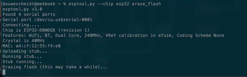
When the ESP32 is wiped, it no longer throws the Guru meditation error. But there is a lot of other output that does not make sense to me... If you have nothing better to do, you can check it out here.
And then, when I try to upload another sketch... the error is back...
21:47:40.461 -> Guru Meditation Error: Core  0 panic'ed (StoreProhibited). Exception was unhandled.
21:47:40.461 -> Core 0 register dump:
21:47:40.461 -> PC      : 0x400e940a  PS      : 0x00060330  A0      : 0x800e0a08  A1      : 0x3ffe3810
21:47:40.461 -> A2      : 0x3ffe3840  A3      : 0x00000000  A4      : 0x00000014  A5      : 0x800e93fb
21:47:40.461 -> A6      : 0xe0000000  A7      : 0xc0000000  A8      : 0x800e93f2  A9      : 0x3ffe3b90
21:47:40.495 -> A10     : 0x0000000c  A11     : 0x00000000  A12     : 0x00002000  A13     : 0x3ff12000
21:47:40.495 -> A14     : 0x000008ff  A15     : 0x00000200  SAR     : 0x00000010  EXCCAUSE: 0x0000001d
21:47:40.495 -> EXCVADDR: 0x800e0a08  LBEG    : 0x40087e26  LEND    : 0x40087e31  LCOUNT  : 0x00000000
21:47:40.495 ->
Wasn't this week supposed to be about reading sensors...?
Instead I have a board that is borderline accaptable in its design and throws errors like an easterbunny throws eggs. Fuck it. No sensor reading was done.
This week is buried under a thick layer of angry mud.
Presenting the darkest week
Of course when everything goes bad and fabacademy life sucks, Neils "random" generator picks you out to present. For later reference here are some snippets of the chat and a link to the video. The chat is saved for good advice that I can follow up when I have time.
15:10:42 From Jani Ylioja: Any change on having pins shorted or connected wrongly? 15:12:31 From Lars Mattern: Guru Error remembers me on the old Amiga :-D 15:18:17 From AgriLab To Everyone : google have api for public transports 15:19:08 From Carl Conquilla To Everyone : @Douwe mine might have been a clock or voltage issue causing brownout issues and memory corruption (just from memory) it might be worth checking your power situation in case you are able to program at a lucky time but not be able to run properly because of corrupted memory 15:19:20 From Carl Conquilla To Everyone : *memory as in my brain memory 15:19:52 From Douwe To Everyone : Thnx Carl! Will look into it 15:19:57 From Carl Conquilla To Everyone : The reg wasn't soldered convincingly from the photo on your page @douwe so it could be worth double checking 15:20:03 From Griffin van Horne To Everyone : I believe there’s a second core that can run on low power as well 15:31:43 From Jason Pettiaux -ULB To Everyone : You mentioned the current burst in the two electrodes capacitive measurements. How do you measure these current bursts the easy way ?
The video is here to remember how much this week sucked just in case I might be happy one day.
Revisiting the board in Week 14.
In week 14 I finally had time to look at this board again. And I want to use it for the assignment that week. So I continue where I left of. I keep the notes here for consistency.
Let's start with inserting this amazing debugging table. and follow some of the advice in the chat. Here is a visual overview of the current setup (with errors on screen)
Debugging the board, round 4.
The ESP32 board works, but reboots and throws guru meditation errors out.
| # | Hypotheses | Debugging | Solved? |
|---|---|---|---|
| 1 | Any change on having pins shorted or connected wrongly? | Use multimeter to check all connections | 0 |
| 2 | mine might have been a clock or voltage issue causing brownout issues and memory corruption (just from memory) it might be worth checking your power situation in case you are able to program at a lucky time but not be able to run properly because of corrupted memory | In round 3 I already attached the ESP32 to 5V instead of 3.3. As there is a regulator on the board, this should hardly make a difference. | 1 |
But it does... suddenly the error is different. Still an error, but a different error nonetheless.
10:26:54.708 -> ets Jun  8 2016 00:22:57
10:26:54.708 ->
10:26:54.708 -> rst:0x1 (POWERON_RESET),boot:0x13 (SPI_FAST_FLASH_BOOT)
10:26:54.745 -> configsip: 0, SPIWP:0xee
10:26:54.745 -> clk_drv:0x00,q_drv:0x00,d_drv:0x00,cs0_drv:0x00,hd_drv:0x00,wp_drv:0x00
10:26:54.745 -> mode:DIO, clock div:1
10:26:54.745 -> load:0x3fff0018,len:4
10:26:54.745 -> load:0x3fff001c,len:1216
10:26:54.745 -> ho 0 tail 12 room 4
10:26:54.745 -> load:0x40078000,len:10944
10:26:54.745 -> load:0x40080400,len:6388
10:26:54.745 -> entry 0x400806b4
10:26:54.854 -> E (125) psram: PSRAM ID read error: 0xffffffff
After reading through many webpages I found a thread on forums.slimdevices.com. In this thread senior member sle118 says:
Squeezelite-esp32 requires external memory to work, so you would need an ESP32 with PSRAM. One such chip is the WROVER. The error in your log shows that more than likely, there's no PSRAM on your module. Could you confirm?
And I realise that all the time I have been compiling for the ESP32-wrover module. Where I use the WROOM module. So maybe there is no PSRAM in mine. and that give a PSRAM ID read error...
If I change the board to use in Arduino IDE to ESP32 Dev Module, the sketch uploads fine and suddenly output from the serial monitor also seems to be error free...
A little more research and confirmation is needed, but as far as I can tell now my Guru meditation error might have been a combo of wrong power and wrong board settings in Arduino IDE.
In the research that followed I successfully compiled, uploaded, and ran a webserver on my ESP32 board. So I think we can conclude it works.
Back to week 14!