Summary
My electronics' Swiss cheese brain is slowly plugging the gaps in my knowledge. I managed to design 2 different boards (with nearly ;) 100% success (see below) from ‘scratch’. And they can (at the moment) communicate in one direction. This system can be replicated with up to 1008 nodes! (with a long enough cable).
What I thought I knew before
Everything I’ve been able to learn and absorb from the other electronics assignments.
Learning Outcomes
Theory and use of things i learnt from this assignment:
- Demonstrate workflows used in network design.
- Implement and interpret networking protocols and/or communication protocols.
Lessons to take away
Double check the values / part numbers of components before soldering on to a board.
Theory
All communication for computers and IC chips, internally and externally (networks) are all passed on the simple principle of a ‘bit’. These are then grouped together to make a ‘byte’ and give more functionality to the data.
Multiples of these are then each given a ‘meaning’ and arranged into a predetermined order by use of a ‘Protocol’. It is this ‘Protocol’ , when used by 2 or more IC’s or computers allows communication between them.
Bits, Bytes, Packets + Messages
- Bit
The bit is the most basic unit of information in computing and digital communications. The name is a contraction of binary digit. The bit represents a logical state with one of two possible values. These values are most commonly represented as either ‘1’ or ‘0’. Other representations such as true/false, yes/no, +/−, or on/off can be used in programming.
- Byte
The byte is a bigger unit of digital information that most commonly consists of eight bits. Some forms of communications and computer functions can use bytes or more.
- Packets
Bytes can be then arrange into ‘packets’ like in UART communication.

Image from Circuit Basics
- Messages
SPI and I2C communication are arranged into a ‘message’.

Image from Circuit Basics
Parity bits, are there as a checking system to see if the amount of bits its received in the data frame is correct.
Data Communication
Electronic devices talk to each other by sending bits of data through wires physically connected between devices. A bit is binary and can only be a 1 or 0. Bits are transferred from one device to another by quick changes in voltage. In a system operating at 5 V, a 0 bit is communicated as a short pulse of 0 V, and a 1 bit is communicated by a short pulse of 5 V.
The bits of data can be transmitted either in parallel or serial form.
-
Parallel
In parallel communication, the bits of data are sent all at the same time, each through a separate wire.

Image from Circuit Basics
- Serial
In serial communication, the bits are sent one by one through a single wire.

Image from Circuit Basics
Protocols
To communicate data internally (in an IC) or externally (on a network), the components or devices need to know what the data it sends or receives means. A set of rules and accepted conventions are called a ‘protocol’, much like there are protocols to do and how to respond to things in life.
Protocols for data are everywhere, the making and displaying of this page is dictated by ‘HTTP’, HyperText Transfer Protocol. Protocols can be grouped in a simple way of 2 types.
- Asynchronous
A common serial port, the kind with Tx and Rx lines, is called ‘asynchronous’ (not synchronous). There is no control over when data is sent or any guarantee that both devices are running at precisely the same rate.
Computers and IC’s normally rely on everything being synchronized to a single ‘clock’ (the main vibrating crystal contained internally in a computer ot IC that drives everything), this can be a problem when two systems with slightly different clocks try to communicate with each other.
To work around this problem, asynchronous serial connections add extra start and stop bits to each byte help the receiver sync up to data as it arrives. Both sides must also agree on the transmission speed (such as 9600 bits per second) in advance. Slight differences in the transmission rate aren’t a problem because the receiver re-syncs at the start of each byte.
An example of asynchronous communication is UART, which stands for Universal Asynchronous Receiver/Transmitter. It’s not a communication protocol like SPI and I2C, but a physical circuit in a microcontroller, or a stand-alone IC. A UART’s main purpose is to transmit and receive serial data.
In UART communication, two UARTs communicate directly with each other. The transmitting UART converts parallel data from a controlling device like a CPU into serial form, transmits it in serial to the receiving UART, which then converts the serial data back into parallel data for the receiving device.
Only two wires are needed to transmit data between two UARTs. Data flows from the Tx pin of the transmitting UART to the Rx pin of the receiving UART.
For more detailed information: UART
- UPDI
 Image from jsykora.info/
The new Microchip AVR MCU generation using UPDI for programming (Older generations use ISP, which needs to use more pins). This is a single-wire interface providing bi-directional half-duplex asynchronous communication for programming the IC. Using just a GND and UPDI pin (optional VCC if no powered supplied by another device).
- Synchronous
A ‘synchronous’ data bus (physical link), means that it uses separate lines for data and a ‘clock’ that keeps both sides in perfect sync. The clock is an oscillating signal (crystal) that tells the receiver exactly when to sample the bits on the data line.
This could be the rising (low to high) or falling (high to low) edge of the clock signal; the device’s datasheet will specify which one to use. When the receiver detects that edge, it will immediately look at the data line to read the next bit.
Because the clock signal is sent along with the data, specifying the speed at which is sends data isn’t important. However devices will have a top speed at which they can operate.
Examples of this type of communications are the protocols ‘SPI’ and ‘I2C’.
- SPI
In SPI (Serial Peripheral Interface), only one side generates the clock signal (usually called CLK or SCK for Serial ClocK). The side that generates the clock is called the ‘controller’, and the other side is called the ‘peripheral’.
There is always only one controller (which is almost always your microcontroller), but there can be multiple peripherals (up to 1008).
When data is sent from the controller to a peripheral, it’s sent on a data line called COPI (sometimes called MOSI), for ‘Controller Out / Peripheral In’. If the peripheral needs to send a response back to the controller, the controller will continue to generate a prearranged number of clock cycles, and the peripheral will put the data onto a third data line called CIPO (sometimes called MISO), for ‘Controller In / Peripheral Out’.
There’s one last line you should be aware of, called CS for ‘Chip Select’ (sometimes called SS). This tells the peripheral that it should wake up and receive / send data and is also used when multiple peripherals are present to select the one you’d like to talk to.
 Image from Circuit Basics
- Networking with SPI
The controller can choose which peripheral it wants to talk to by setting the peripheral’s CS/SS line to a low voltage level. In the idle, non-transmitting state, the slave select line is kept at a high voltage level. Multiple CS/SS pins may be available on the master, which allows for multiple slaves to be wired in parallel. If only one CS/SS pin is present, multiple peripherals can be wired to the master by daisy-chaining.
It is the ‘Address frame’ (see diagram above) that is used to carry the address data of which chip should be selected.
Because the controller (and therefore also peripherals) need 4 pins to communicate, its is a less popular protocol to use than I2C.
-
Programming
#include <SPI.h>
You can use the shiftIn() and shiftOut() commands. These are software-based commands that will work on any group of pins, but will be somewhat slow.
Or you can use the SPI Library, which takes advantage of the SPI hardware built into the microcontroller. This is vastly faster than the above commands, but it will only work on certain pins.
There is also a dedicated CS pin that you can use (which must, at least, be set to an output in order for the SPI hardware to function), but note that you can use any other available output pin(s) for CS to your peripheral device(s) as well.
For more detailed information: SPI
-
Example:
// Define client addresses #define CLIENT1 0x01 #define CLIENT2 0x02 // Define client commands #define STOP 0x04 #define START 0x08 void setup() { Serial.begin(9600); pinMode(LED_BUILTIN, OUTPUT); } void loop() { // Turn LED off (to indicate client1) digitalWrite(LED_BUILTIN, HIGH); // Send command START to CLIENT1 Serial.print(CLIENT1, BIN); // Send address for client 1 Serial.print(START, BIN); // Send the command // Wait 5 seconds delay(5000); // Turn LED on (to indicate client2) digitalWrite(LED_BUILTIN, LOW); // Send command START to CLIENT2 Serial.print(CLIENT2, BIN); // Send address for client 2 Serial.print(START, BIN); // Send the command // Wait 5 seconds delay(5000); } -
I2C
 Image from sparkfun.com
I2C protocol (Inter-Integrated Circuit), only uses two wires for communication (SDA - data, and SLK - clock). Within the protocol there is already the ability to support multiple controller and peripherals. It also has the advantage of a transferred successfully checking system in the ACK/NACK confirmation bits.
-
Networking with I2C
Single controller with multiple peripherals
Because I2C uses addressing, multiple slaves can be controlled from a single master. With a 7 bit address, 128 (27) unique address are available. Using 10 bit addresses is uncommon, but provides 1,024 (210) unique addresses. To connect multiple slaves to a single master, wire them with 4.7K Ohm pull-up resistors connecting the SDA and SCL lines to Vcc.
Multiple controllers with multiple peripherals
Multiple masters can be connected to a single slave or multiple slaves. The problem with multiple masters in the same system comes when two masters try to send or receive data at the same time over the SDA line. To solve this problem, each master needs to detect if the SDA line is low or high before transmitting a message. If the SDA line is low, this means that another master has control of the bus, and the master should wait to send the message. If the SDA line is high, then it’s safe to transmit the message. Multiple controllers with multiple peripherals systems need 4.7K Ohm pull-up resistors connecting the SDA and SCL lines to Vcc.
-
Programming
Wire Library allows you to communicate with I2C / TWI devices. On the Arduino boards with the R3 layout (1.0 pinout), the SDA (data line) and SCL (clock line) are on the pin headers close to the AREF pin.
‘SoftWire’ is a software I2C implementation for Arduino and other Wiring-type environments. It utilises the pinMode(), digitalWrite() and digitalRead() functions. The pins to be used for the serial data (SDA) and serial clock (SCL) control lines can be defined at run-time. Alternatively it is possible to pass references to functions which read and control the SDA and SCL lines, thereby allowing direct port manipulation to be used if preferred. Multiple objects (for multiple software I2C buses) and clock-stretching by peripheral devices are supported. A timeout feature is included to prevent lockups by faulty or missing hardware. The microcontroller must function as the controller device, multiple controllers are not supported.
For more detailed information: I2C
-
Example:
 #include <Adafruit_I2CDevice.h>

 Adafruit_I2CDevice i2c_dev = Adafruit_I2CDevice(0x10);

 void setup() {
   // Initialize serial port
   while (!Serial) {
     delay(10);
   }
   Serial.begin(115200);
 }

 void loop() {
 Serial.println("I2C address detection test");

 // Loop throuth all possible i2c addresses
 for (char i = 0; i < 127; i++) {
   // Send address
   Adafruit_I2CDevice i2c_dev = Adafruit_I2CDevice(i);

 // If response on address, print address
   if (i2c_dev.begin()) {
     Serial.print("Device found at 0x");
     Serial.println(i2c_dev.address(), HEX);
   }
 }
 // Wait 5 seconds, then rescan
 delay(5000);
 }
Group Assignment

- Send a message between two projects
What we did
The task was to link 2 LCD screens on the same I2C bus. As a group we decided to form one large group, where those individuals with more knowledge of communications and networks could teach us all. We set up a power bank, two Arduinos with screens attached (OLED and LCD) and a laptop to program and debug.
Once that was all arranged, very few hands were needed to operate them. So my role was to listen and try to understand what was going on. That role i did very well and what i learnt was of a deeper level and more quickly than had we been in a smaller group with less initial combined knowledge of the subject.
See the Group Page for further details.
Mistakes & Issues
See the Group Page for further details.
Individual Assignment

- Design, build, and connect wired or wireless node(s) with network or bus addresses.
Concept
At first look at the individual assignment I thought we were meant to join our projects with others as the network. So I came up with the idea to make a ‘breakout board’ that could talk both SPI and I2C, that way i could be sure that it could talk to anything.
I had noticed from last week that the ATtiny1614 had separate pins for each of the parts of the different protocols, so this would be pretty straight forward (in my inexperience mind at least). Add an output and an input to the IC and i would have a development board that I could use in the future with any sensor that spoke SPI or I2C (e.g. my 3 axis accelerometer for instance).
What I did
I took a bit of inspiration from the Adrianino. The way it breaks out all the pins of the ATtiny1614 for various communications and functions. This would be the ‘Controller’ board, being able to communicated on different protocols. And for the secondary boards i’d take inspiration from the LED boards of the previous weeks as the simplest circuits to make to be controlled. Using I2C as the communication protocol I could gain an understanding of how to program with it and use that form my 3 axis accelerometer in the future.
Design criteria
- Knowing the 3 axis accelerometer need 3.3v, it would be useful if the board had the ability to deliver 3.3v or 5v.
- Even though SPI and I2C don’t need the same amount of pins to communicate over, by using the same AVR 6 pin header connections for both protocols, I can use the same cable to network tiny boards whatever the protocol.
- With the spare pins left on the board after the protocols have had theirs, i’ll add an input and it’s own output (or 2) to give more possibilities of functionality.
Initial decisions
I felt confident enough in the boards I’ve previously produced to design these boards by taking inspiration from them.
BOM - Controller Board


| COMPONENT | DESCRIPTION | DATA SHEET | SPECIFICATIONS |
|---|---|---|---|
| 3 UPDI Header pins | To allow board programming/UPDI communication. Plus power 5v | Non-polarity. | |
| ATtiny1614 | More pins and memory than the ATtiny412. | ATtiny1614-16-17-DataSheet-DS40002204A.pdf | Polarity |
| Voltage regulator | To drop the input voltage by 1.2 v for the sensor. | LM3480_datasheet.pdf | Polarity |
| Capacitor (1µF) | To stabilize power signal. | Non-polarity | |
| Resistor (0 Ohm) x6 | To use as a bridge for tracks to run underneath. | Non-polarity. | |
| Resistor (1k Ohm) x2 | To control amount of current going to the separate LEDs | Non-polarity. | |
| Resistor (4.9k Ohm) x2 | ‘Pullup’ resistors to control amount of current going to the SDA + SCL lines | Non-polarity. | |
| Button B3 SN | Input source. | Non-polarity. | |
| FTDI header pins | To allow serial communication. | Non-polarity. | |
| RGB LED, CLV1A-FKB | RGB colour combinations. | RGB-LED-datasheet.pdf | Polarity |
| 2x3 SPI Header pins x2 | To allow board SPS or I2C communication. | Non-polarity. | |
| switch | To switch between 3.3v and 5v. | Non-polarity. |
BOM - Baby Boards


| COMPONENT | DESCRIPTION | DATA SHEET | SPECIFICATIONS |
|---|---|---|---|
| RGB LED, CLV1A-FKB | RGB colour combinations. | RGB-LED-datasheet.pdf | Polarity |
| Resistor (499 Ohm) | To control amount of current going to the Blue of the RGB LED | Non-polarity. | |
| Resistor (1k Ohm) x2 | To control amount of current going to the Red + Green of the RGB LED | Non-polarity. | |
| ATtiny412 | IC | Attiny212-412_datasheet.pdf | Polarity |
| Capacitor (1µF) | To stabilize power signal. | Non-polarity | |
| 2x3 SPI Header pins | To allow board I2C communication. | Non-polarity. | |
| Resistor (0 Ohm) x1 | To use as a bridge for tracks to run underneath. | Non-polarity. |
KiCAD

-
Set up project.
-
Open ‘schematic layout editor’.
- Place ‘Symbols’.
- Attach ‘Global labels’.
- Place direct connections with ‘Wire’s if needed.
- Place ‘no connection’ where needed (to stop errors).
- Place ‘PWR FLAG’s to suppress power errors.
- Run ‘Electrical Rules Check’.
- Run ‘Assign PCB footprints to schematic symbols’.
- Run ‘PcbNew to layout printed circuit board’.
-
Set design rules with ‘Board Setup’.
- Track ‘Routes’ and manipulate components rotation/position.
- Run ‘Perform design rules check’.
- Draw outline of board with ‘graphic polygon’ tool, on ‘Edges cut’ Layer.
- Export ‘.svg’, for the traces layer (‘F.Cu’) and interior layer (‘Edges cut’).
What i think the circuits do.
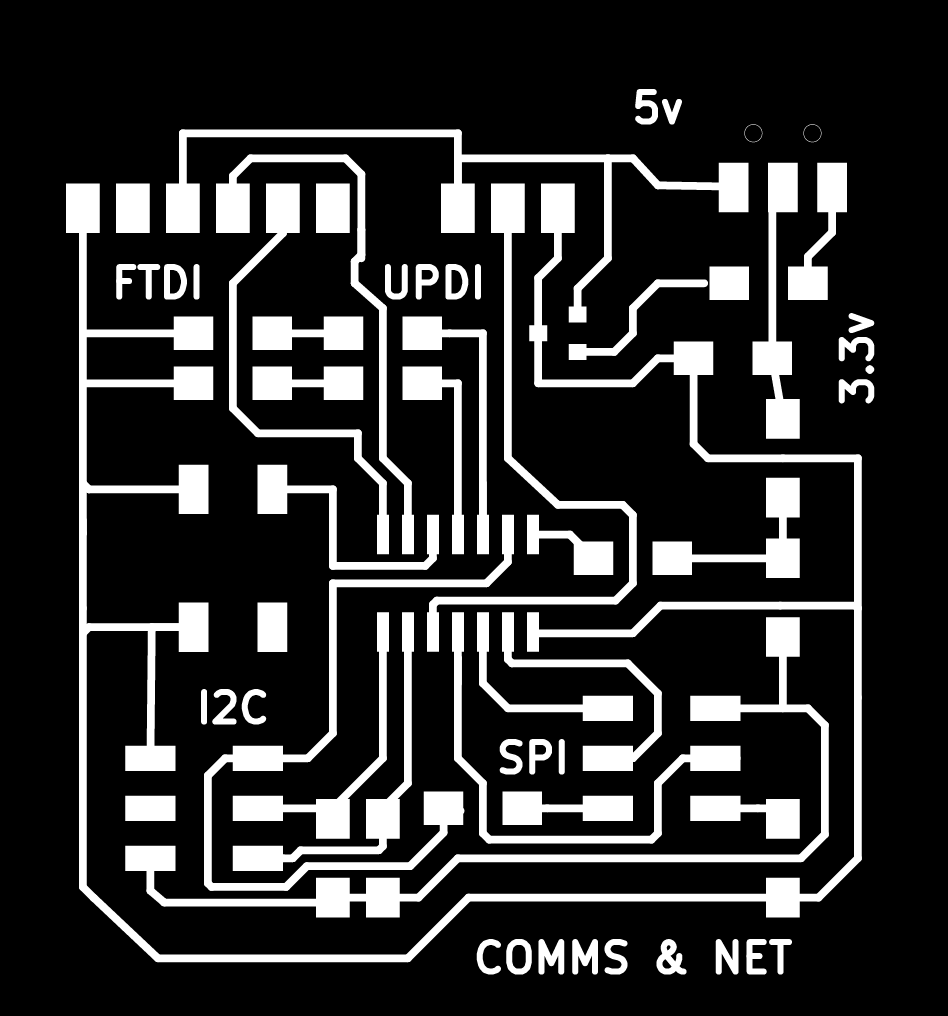
- Controller
For the controller board, power comes in through the FTDI or UPDI sets of pins depending on whether i’m programming or debugging with the serial port. This is then either regulated down to 3.3v or stays at 5v, depending on the setting of the switch.
The capacitor smooths out that power and delivers it around the board, and to the power pins fo the SPI and I2C headers. That way any networked IC boards or attached sensors can be also draw power.
The button input and LED outputs can be programmed to activate or give visual feedback on either the control board or other networked boards.
- Peripherals
The peripheral should be able to be programmed with the first line of pins (UPDI+VCC) of the header. The second line includes the SDA and SCL lines for I2C protocol communication. The ATtiny412 then controls the RGB LED. Simple as that. Whilst connected with the ‘network’ cable, it should take the VCC and GND from the controller board along with the SDA and SCL lines. The headers on all boards will have matching header pin assignments.
Board Production
As the controller board was my biggest board so far (no need to minimise space used this time) it took a a lot longer than expected to mill. I combined two images of the smaller board in Photoshop and milled these separately from the main controller. The smaller baby boards took less time with fewer traces to mill.
I learnt previously that i should leave a bit more space between the edge of the board and the circuit, as with small boards its easy to forget that measurements are in reality very small compared to what you see on a big computer screen. This negated the possibility of cutting circuit traces when the board was cut out at the end.
Soldering the board
As usual, positioning these small components with small connection points was the most difficult. Tinning these and the pads where they would go with the minimum amount of solder was important. Flux was my friend here, as it ensured that the small amount of solder on both surfaces was enough to make a firm connection.
Apart from the usual trickiness of soldering such small components, the biggest frustrations were making sure that the LEDs (also the RGB LED) were positioned in the right configuration to work. I didn’t want to have to unsolder and swap them around later. Which is something i did have to do when I found out i had put on the wrong ‘pullup’ resistors (see below for more detail).
Board Testing
- Continuity testing
This ‘sounded’ like there were no missed or extra connections in the wrong places. Adding VCC and GND connections to the baby boards showed that the RGB LEDs were connected in the right way. I had confidence that any following problems were more than likely going to be programming ones and not hardware.
Programming

The idea was to use previous code from my other boards to program LED functions onto the peripherals. See Week 12.
A different program on the controller would broadcast a ‘message’ and the nodes would then activate a LED function based on that message.
The main part of the programming would be to find out how to send and receive signals - and then how the receiver board deals with it.
-
Include the correct library e.g. Wire (I2C for Arduino)
e.g. #include <Wire.h></Wire.h> -
Start Serial communication
Serial.begin(baudrate); -
Join I2C bus
Wire.begin(optional address); // Controller doesn't necessarily need an address -
Transmit
Wire.beginTransmission(node_address); // transmit to a specific node Wire.write(myMessage); // send bytes Wire.endTransmission(); // stop transmission -
Receive
    Wire.onReceive(receiveEvent); // register event
    /// in a function
    void receiveEvent(int howMany) {
       int x = Wire.read(); // receive byte as an integer
       // do something
    }
These functions would be used on the different boards depending on their proposed functionality.
What I should’ve done
I probably should’ve found out that SDA and SCL need pullup resistors for communicating before I started designing my controller board. I think I would’ve queried the use of these resistors if I had been trying to replicate or modify one of the Neil’s sample boards, or more thoroughly researched IC2 communication.
Mistakes & Issues
Big design

My first ‘baby’ board i designed was a little big i thought and would take too long to mill based on how many people needed to use the milling machine. It was based on the ‘master’ board with a ATtiny1614 with both SPI and I2C connections. I decided to use the ATtiny412 and only have I2C connections, so i would use something different from the controller board and minimise the amount of space used.
Rx + Tx around the wrong way again
Another board with the Rx+ Tx around the wrong way. I purposely designed this the other way around from my last board that was wrong. So I solved this for future boards by changing the labelling on the footprint of the FTDI headers in my KiCad library. Rx labels will now all connect to Rx tags on foot prints and labels. The same with the Tx line.
Pullup resistors
Upon designing the baby boards, I read that ‘pullup’ resistors were needed with the SDA and SCL lines which connect to VCC. It wasn’t really possible to save the control board by adding the extra resistors, so I redesigned the control board with the extra resistors and also the Rx + Tx around the right way this time.
One track not seperated
Even though the design rule check didn’t high light any problems, one trace was not separated completely from the rest. I fixed with with a steady hand and a Stanley knife!

Wrong resistors
Whilst trying to program a ‘broadcast’ message that would send a message to the nodes, the ‘Serial.endTransmission’ command would freeze. A search on the internet produced a few results, but no solution that was relevant. But a second pair of Eagle eyes (Nadieh) noticed that the resistors had a strange value. I had picked out resistors that had fallen (or were recycled) from the bottom of the box and not from the packaging. It turns out that someone had placed 4.9 Ohm resistors in the 4.9k Ohm box. Replacing these with the correct ones on the board made everything work! Serial.endTransmission completed its command and i could move on with programming.
Only RED RGB turned on
When testing the RGB LED nodes, only the Red LED would turn on. Commenting things out to debug, the result showed that it was the ‘Serial.begin(9600)’ command that was stopping all the LEDs turn on. I checked the program and tried different things to directly manipulate the LEDs, but with no solution. Then I remembered our old friend ‘Serial.swap(1)’ from the previous weeks. I wondered if changing the serial pin mapping would solve the problem - And it did!! :) A lot of time saved from debugging that problem.
Ran out of memory on ATtiny412

Part of designing a board with an RGB LED would mean i could re-use previous code from other weeks. In the process of trying to load this code onto the board I began to get ‘compile’ problems when i tried to upload to the board. Debugging the code by commenting out code helped, but an internet search lead me to believe that my program was too much for the chip. It gave the impression that it was in the region of 80% of the memory quota, however what this code included this time from previous weeks was the Wire Library. This must have a memory overhead before the programming is written. Further investigation into the program wasn’t possible (see next).
UPDI failed to initialise

I then had trouble uploading the programs, with the error ‘UPDI failed to initialise’. I swapped USB ports, changed connecting wires, and even restarted the computer. Only thing left to do now is to use another UPDI to check if my UPDI works.
CONCLUSION
I have one foot firmly inside the door that is Networking and Communications. From which I can expand my knowledge of using different protocols and deepen what I now know. My confidence in Electronics is growing.
FILES
| FILE | DESCRIPTION |
|---|---|
| Controller Traces | The Controller traces for milling. |
| Controller Interior | The Controller interior for milling. |
| Peripheral Traces | The Peripheral traces for milling. |
| Peripheral Interior | The Peripheral interior for milling. |
| Controller Arduino Sketch - on/off | The Controller sketch. |
| Peripheral Arduino Sketch - on/off | The Peripheral sketch. |