-
01. Principles and practices
-
02. Project management
-
03. Computer-Aided design
-
04. Computer controlled cutting
-
05. Electronics production
-
06. 3D Scanning and printing
-
07. Electronics design
-
08. Computer controlled machining
-
09. Embedded programming
-
10. Input devices
-
11. Applications and implications
-
12. Output devices
-
13. Interface and application programming
-
14. Invention, intellectual property and income
-
15. Networking and communications
-
16. Molding and casting
-
17. Wildcard week
-
18. Machine design
-
19. Project development
-
Glossary
Week 9. Embedded programming
March 25, 2020
Assignment
Group assignment
- compare the performance and development workflows for other architectures
Individual assignment
- Read a microcontroller data sheet
- Program your board to do something, with as many different programming languages and programming environments as possible
Individual assignment
During the electronics design week, I made a board with ATtiny1614 and wrote a simple LED control program and downloaded it to the board.
        int ledPin = 2;  # // This is the pin of the ATtiny1614 connected to the REDled
        int buttonPin = 1; # // This is the pin of the ATtiny1614 connected to the button
        int buttonState = 0;


        void setup() {
        pinMode(ledPin, OUTPUT);
        pinMode(buttonPin, INPUT_PULLUP);
        Serial.begin(115200);
      }

      void loop() {
      buttonState = digitalRead(buttonPin);
      if (buttonState == LOW) {
      Serial.print("BUTTON ON"); # // It’s a pull up button, so the LED is on when the buttonState is LOW

      Serial.println("\"");
      digitalWrite(ledPin, HIGH);
      delay (50);
      digitalWrite(ledPin, LOW);
      delay (50);
    }
    else {
    Serial.print("BUTTON OFF");
    Serial.println("\"");
    digitalWrite(ledPin, LOW); # // If the button is not pressed the RED light is off.

  }
}
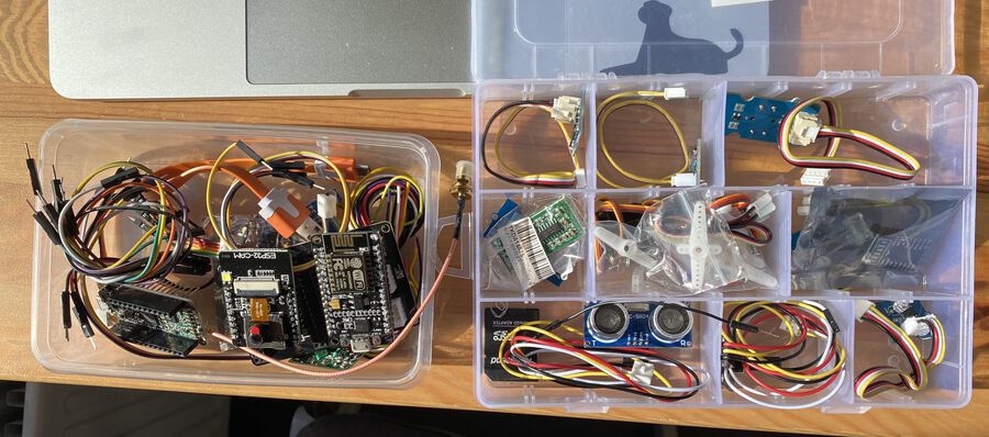
This week, Henk gave us a kit filled with a lot of electronics components. Also, one of my fellow students, Harm gave us another electronics kit which he got from the university he works at.
Attiny1614
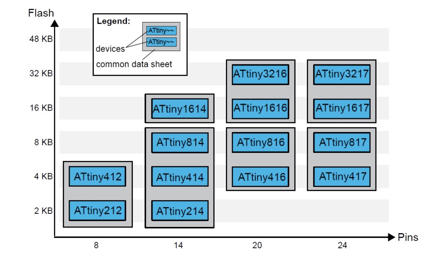
14 pin package.
Two internal clocks 16 and 20 MHz.
16 KB Flash Memory.
256 B EEPROM.
2 KB SRAM.
Maximum voltage: 6V; minimum voltage -0.5 V.
After looking at the basic features, you will find the pinning of the microcontroller.
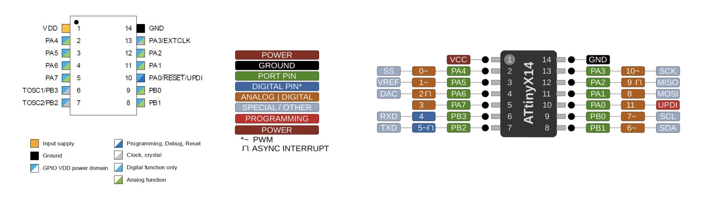
VDD: Supply voltage.
GND: Ground.
Digital pins: Port A: PA0, PA1, PA2, PA3, PA4, PA5, PA6, PA7. Port B: PB0, PB1, PB2, PB3.
Analog pins: PA1, PA2, PA3, PA4, PA5, PA6, PA7. Port B: PB0, PB1.
UPDI Programming pin: PA0 (physical pin number 10).
External Clock Pin: PA3.
USART - Universal Synchronous and Asynchronous Receiver and Transmitter: It has the RX (PB2 or PA2) and the TX (PB3 or PA1).
SPI - Serial Peripheral Interface: It has only MOSI (PA1), MISO (PA2), SCK (PA3), SS (PA4) .
TWI - Two Wire Interface (I2C): It has SDA (PB1 or PA1) and SCL (PB0 or PA2).
All I/O pins can be configured with internal pullup resistance. Within the communications section there are different types and their pins are different. It is clear that the different communication protocols cannot all be used at the same time, because they have pins in common.
NodeMCU 1.0
NodeMCU is a low-cost open source IoT platform. It initially included firmware which runs on the ESP8266 Wi-Fi SoC from Espressif Systems, and hardware which was based on the ESP-12 module.
- Wikipedia
For this week's assignment, I wanted to play with an ESP32. It has both Wi-Fi and Bluetooth features, which I need for my final project. But the kit doesn’t include the ESP32. Instead, there was a NodeMCU 1.0 development module which included a ESP8266 chip in it. NodeMCU1.0 doesn’t support Bluetooth, but I decided to use it because it is pretty similar to ESP32.
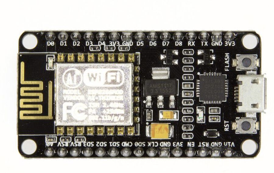
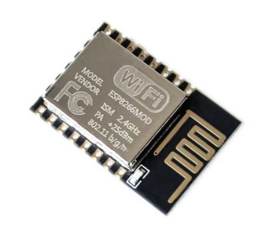
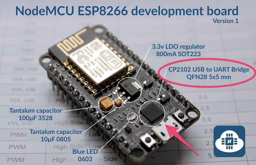
1) ESP-12E Module
The development board equips the ESP-12E module containing ESP8266 chip (I will explain this module and chip later).
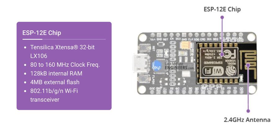
The ESP8266 has 802.11b/g/n HT40 Wi-Fi transceiver, so it can not only connect to a WiFi network and interact with the Internet, but it can also set up a network of its own, allowing other devices to connect directly to it.
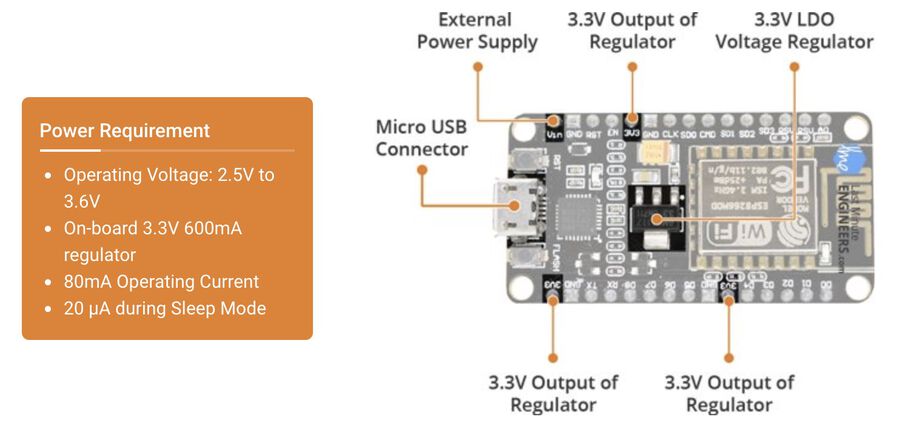
2) Power Requirement
As the operating voltage range of ESP8266 is 3V to 3.6V, the board comes with a LDO (Low-dropout) voltage regulator to keep the voltage steady at 3.3V. It can reliably supply up to 600mA, which should be more than enough when ESP8266 pulls as much as 80mA during RF (Radio Frequency) transmissions. Power to the ESP8266 NodeMCU is supplied via the on-board MicroB USB connector. Alternatively, if you have a regulated 5V voltage source, the VIN pin can be used to directly supply the ESP8266 and its peripherals.
3) Peripherals and I/O
The ESP8266 NodeMCU has 17 GPIO pins. These pins can be assigned to all sorts of peripheral duties such as ADC channel, UART, PWM outputs, SPI/I2C interfaces (for sensors and peripherals), and I2S (to add sound).
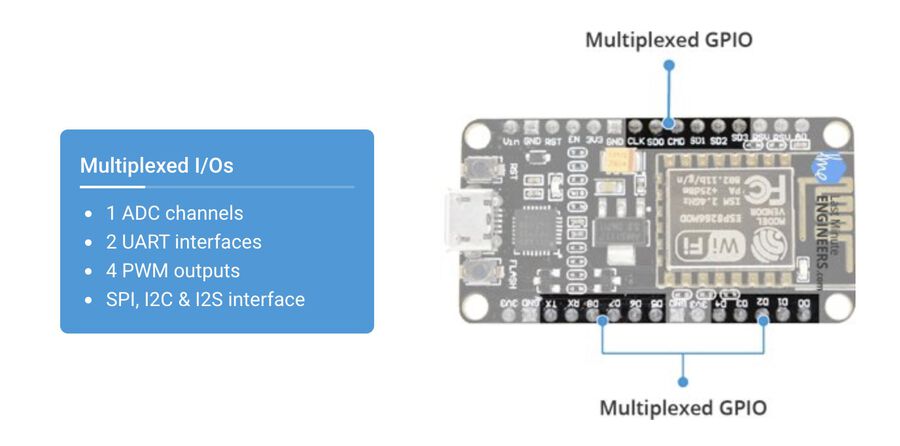
Thanks to the ESP8266’s pin multiplexing feature, a single GPIO pin can act as PWM/UART/SPI.
4) On-board Switches & LED Indicator
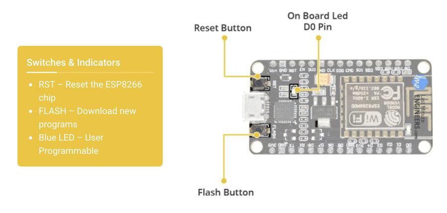
This module has a reset button and flash button. The reset button is used to reset the ESP8266 chip and the flash button is used while upgrading firmware. The board also has a LED indicator which is programmable and is connected to the D0 pin of the board.
5) Serial Communication
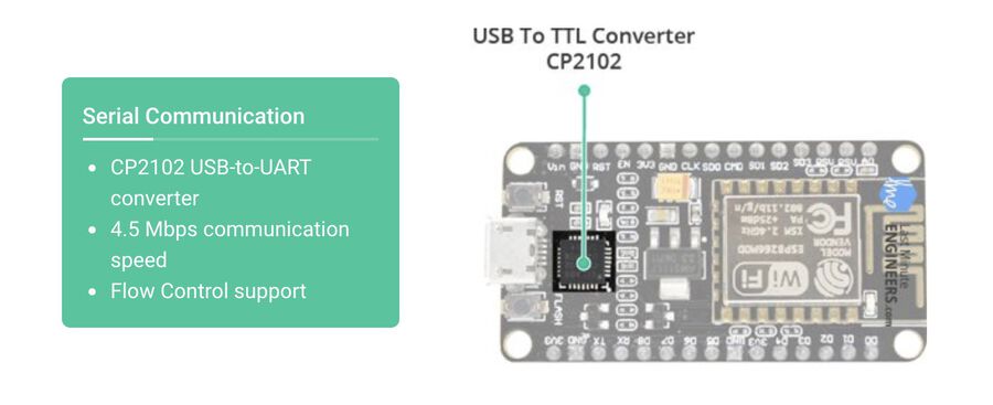
The board includes a USB-to-UART converter which converts USB signal to serial. It allows your computer to program and communicate with the ESP8266 chip. You might need to download the CP2102 driver to your PC. I downloaded it from here.
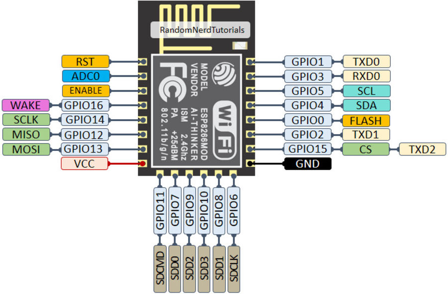
6) Pinout
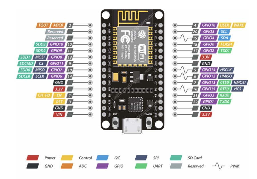
Power Pins There are four power pins, one VIN pin and three 3.3V pins. If you have a regulated 5V voltage source, you can use a VIN pin. The 3.3V pins can be used to supply power to external components.
GND A ground pin.
I2C Pins These pins can be used to hook up all sorts of I2C sensors and peripherals. Both I2C master and slave are supported and the maximum clock frequency is 100 kHz.
GPIO pins The NodeMCU has 17 GPIO pins which can be assigned to various functions such as I2C, I2S, UART, PWM, IR Remote Control, LED Light and Button programmatically. Each digital enabled GPIO can be configured to internal pull-up or pull-down, or set to high impedance. When configured as an input, it can also be set to edge-trigger or level-trigger to generate CPU interrupts.
ADC Channel The NodeMCU is embedded with a 10-bit precision SAR ADC.
UART Pins The NodeMCU has 2 UART interfaces (UART0, UART1) which can communicate at up to 4.5Mbps. UART0 (TXD0, RXD0, RST0 & CTS0 pins) can be used for communication while UART1 (TXD1 pin) can only be used for printing logs.
SPI Pins There are two SPIs (SPI and HSPI) in slave and master modes.
SDIO Pins ESP8266 features Secure Digital Input/Output Interface (SDIO) which is used to directly interface SD cards.
PWM Pins The board has 4 channels of PWM. The PWM output can be used for driving digital motors and LEDs. The PWM frequency range is adjustable between 100 Hz and 1 kHz.
Control Pins There are three kinds of control pins.
EN pin: The ESP8266 chip is enabled when EN pin is pulled HIGH, and the chip works at minimum power when pulled LOW
RST pin: It is used to reset the ESP8266 chip
WAKE pin: It is used to wake the chip from deep-sleep
ESP-12E & ESP8266
As mentioned above, NodeMCU has a ESP-12E raw module on it. ESP-12E is a miniature Wi-Fi module used for a wireless network connection for microcontroller or processor. The core of ESP-12E is ESP8266EX which is a high integration wireless SoC (System on Chip).
The ESP8266 is a low-cost Wi-Fi microchip, with a full TCP/IP stack and microcontroller capability, produced by Espressif Systems in Shanghai, China.
- Wikipedia
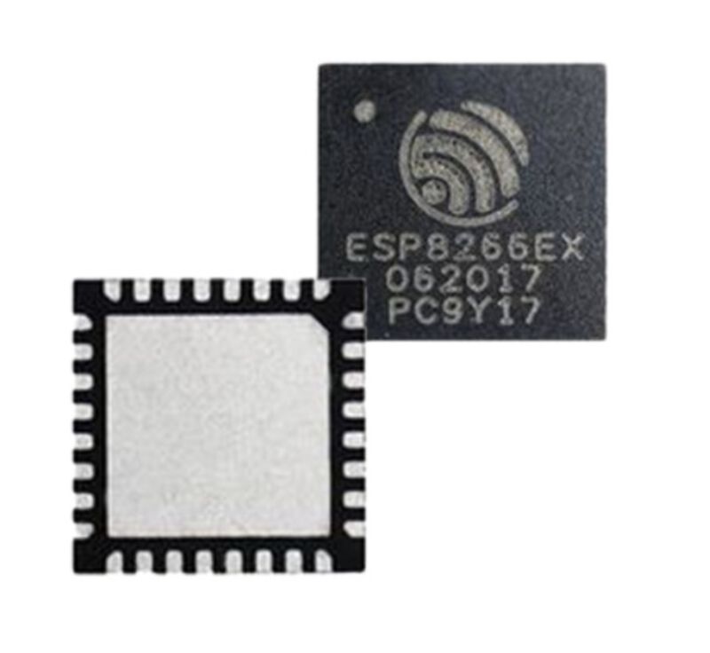
The ESP8266EX chip (left) and the ESP-01 module by Ai-Thinker (right)
1) Pinout
There are 22 pins on the ESP-12E and 32 pins on the ESP8266 chip.
ESP-12E Pinout
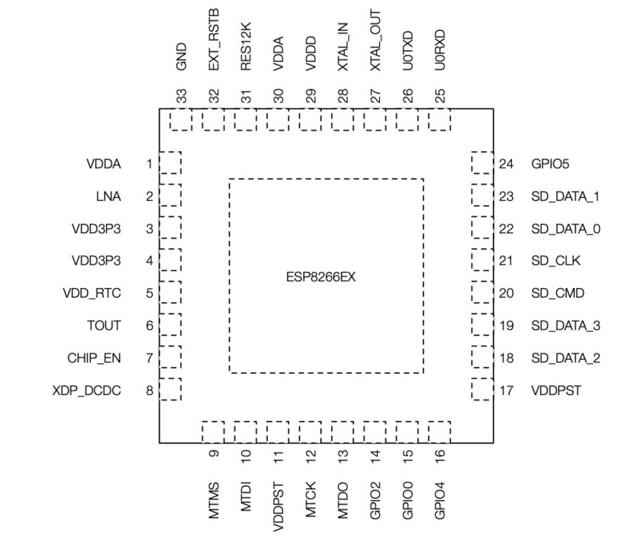
ESP8266 Pinout
2) CPU
ESP8266 CPU integrates a 32-bit RISC processor. The Real-Time Operating System (RTOS) and Wi-Fi stack allow 80% of the processing power to be available for user application programming and development. It also includes programmable RAM/ROM interfaces which can be connected with a memory controller.
3) Memory
ESP8266EX Wi-Fi SoC integrates a memory controller and memory units including SRAM and ROM. MCU can access the memory units through iBus, dBus, and AHB interfaces. There is no programmable ROM in the SoC. Therefore, the user program must be stored in an external SPI flash.
4) External Flash
ESP8266EX uses external SPI flash to store user programs, and supports up to 16 MB memory capacity theoretically.
5) Clock
The high frequency clock is generated from an internal crystal oscillator and external crystal. The crystal frequency ranges from 24 MHz to 52 MHz.
6) Radio
ESP8266EX radio consists of 2.4 GHz receiver and transmitters, High speed clock generators and crystal oscillator, bias and regulators, and Power management
7) Wi-Fi
ESP8266EX implements TCP/IP and full 802.11 b/g/n WLAN MAC protocol.
8) Power Management
ESP8266EX is designed with advanced power management technologies and intended for mobile devices, wearable electronics and the Internet of Things applications. The lower-power architecture has Active mode, Modern-sleep mode, Light-sleep mode and Deep-sleep mode.
9) GPIO
ESP8266EX has 17 GPIO pins which can be assigned to various functions by programming the appropriate registers. Each GPIO PAD can be configured with internal pull-up or pull-down. These pins, when working as GPIOs, can be multiplexed with other functions such as I2C, I2S, UART, PWM, and IR Remote Control, etc.
10) Secure Digital Input/Output Interface (SDIO)
ESP8266EX has one Slave SDIO
11) Serial Peripheral Interface (SPI/HSPI)
ESP8266EX has a general Slave/Master SPI and a general Slave HSPI.
12) I2C Interface
ESP8266EX has one I2C, which can be used to connect with other microcontrollers and other peripheral equipment such as sensors.
13) I2S Interface
ESP8266EX has one I2S data which can be mainly used for data collection, processing, and transmission of audio data, as well as the input and output of serial data.
14) UART Interface
ESP8266EX has two UART interfaces UART0 and UART1
15) PWM Interface
ESP8266EX has four PWM output interfaces. The functionality of PWM interfaces can be implemented via software programming. PWM frequency range is adjustable from 1000 μs to 10000 μs, i.e., between 100 Hz and 1 kHz.
16) IR Remote Control Interface
ESP8266EX currently supports one infrared remote control interface. The functionality of Infrared remote control interface can be implemented via software programming
17) ADC (Analog-to-Digital Converter) Interface
ESP8266EX is embedded with a 10-bit precision SAR ADC. There are two ways to implement this. One is to measure the power supply voltage of VDD3P3 (Pin 3 and Pin 4), and the other is to measure the input voltage of TOUT (Pin 6).
Program NodeMCU with different options
I usually use the Arduino IDE and C++ combination to program my board. I tried out VS Code (with PlatformIO) and MicroPython to see what the differences were. I already had VS Code installed, so I only needed to install the PlatformIO package on it. For this test, I used some simple code which controlled an RGB LED.
        #include <Arduino.h> // add this line when using VS Code (it’s not needed in Arduino IDE)

        int R_led = 16;
        int G_led = 5;
        int B_led = 4;

        int R_brightness = random(0, 255);
        int G_brightness = random(0, 255);
        int B_brightness = random(0, 255);

        void setup() {
        pinMode(R_led, OUTPUT);
        pinMode(G_led, OUTPUT);
        pinMode(B_led, OUTPUT);
      }

      void loop() {
      analogWrite(R_led, R_brightness);
      analogWrite(G_led, G_brightness);
      analogWrite(B_led, B_brightness);

      delay(2000);

      R_brightness = random(0, 255);
      G_brightness = random(0, 255);
      B_brightness = random(0, 255);
    }
Option 1. Arduino IDE & C++
1) How to use
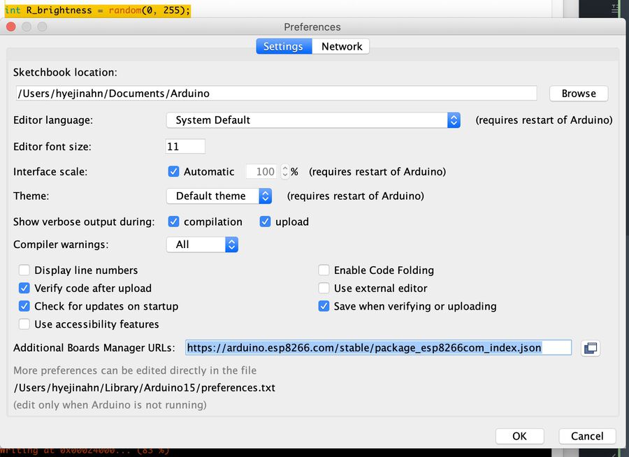
NodeMCU1.0 has a USB to UART Bridge(CP2102) on it, so you can program it directly through the USB port.
To use this bridge, you have to download the NodeMCU driver for USB from here. Once the installation is done, open Arduino IDE. Go to Arduino > Prefereces and fill out the Additional Boards Manager URLs field to https://arduino.esp8266.com/stable/package_esp8266com_index.json. If you're going to use other boards, you have to search the Board Manager URL corresponding to them.
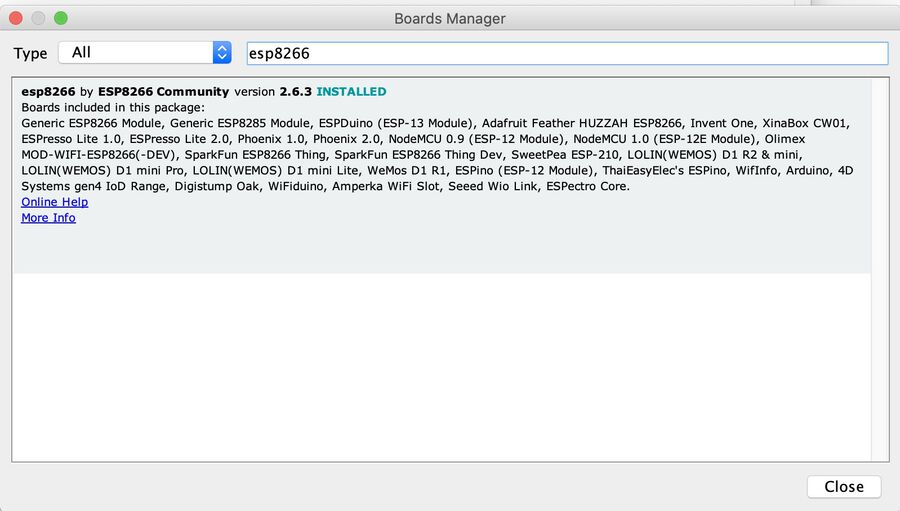
Then, go to Tools > Boards Manager and search for esp8266 and download the library.
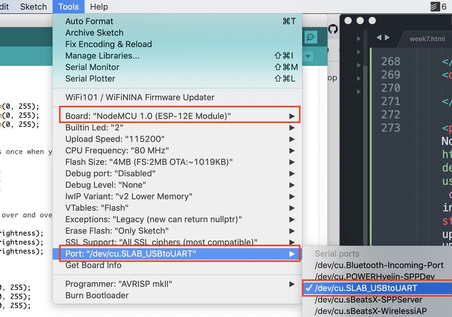
Once it's downloaded, go to Tools and choose NodeMCU 1.0 (ESP-12E Module) for the board, and make sure to select the USB to UART port for the port option.
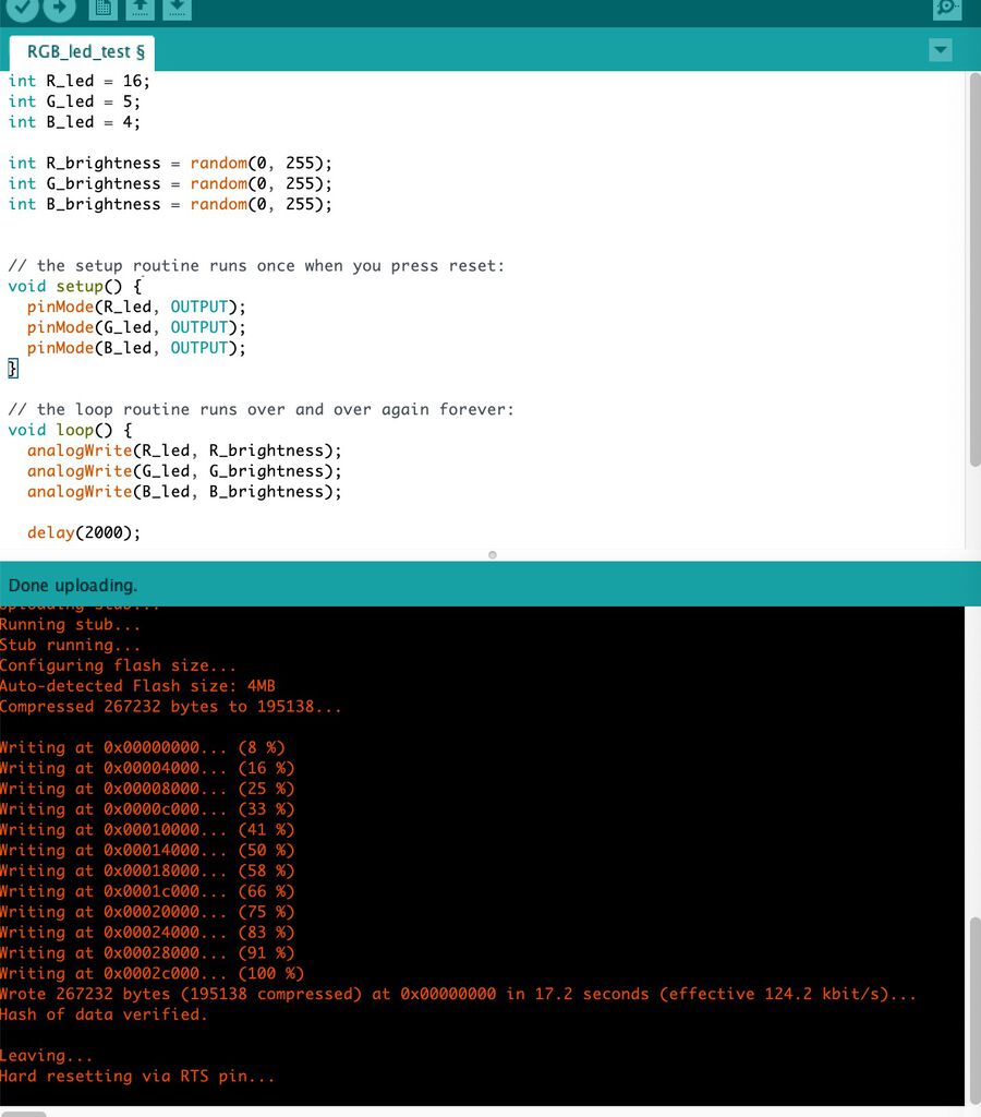
After writing a program, click the Verify button, and then click the Upload button.
2) Pros and cons
Pros Since I'm already familiar with Arduino IDE, it wasn’t hard for me to use it. The Arduino IDE also has a lot of users and active communities, so you can find some help easily. Also, there are a lot of built-in examples as well as tutorials on the internet which are very helpful for beginners.
Cons Arduino IDE doesn't have an autocomplete feature which is a big big downside. I have to type every single function and variable names and it is extremely time-consuming. Also, it doesn't tell you if there's any errors until it gets compiled. And uploading a program takes a pretty long time. For example, the simple LED code took 17 seconds to get uploaded. It's good enough to use for hobbyists, but not as good as other existing IDEs.
Option 2. VS Code & C++ & PlatformIO
1) How to use
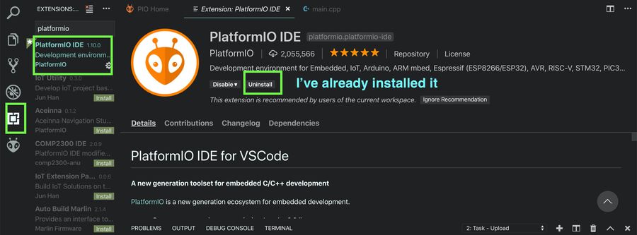
You can use PlatformIO with other IDEs such as Atom, Emacs, Sublime Text, Vim, Visual Studio and so on. For the IDE, I used VS Code since it’s already installed on my computer. First, open VS Code and click the Extension icon on the left bar. Then, search for PlatformIO and install it.
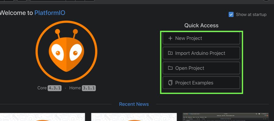
Once it's installed, you will see the welcome screen for PlatformIO. Click New Project, or Import Arduino Project if you want to import an existing project.
I created a new project and chose the NodeMCU 1.0 for the board option. Once the project is created, you will see some files and directories. You can write your program in the src > main.cpp file. Unlike Arduino IDE, you have to add #include <Arduino.h> on the first line of your program.
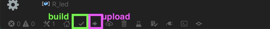
Once finishing writing the code, click the check icon on the bottom bar to build the code. Then, click the arrow icon to upload it.
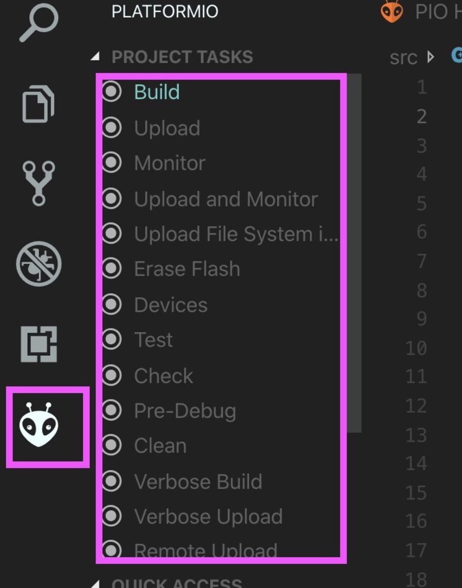
You can also click the alien icon on the left bar and run a task by clicking buttons. I've only tried the Build and Upload buttons, but there are more buttons such as Upload and Monitor or Erase Flash.
2) Pros and cons
Pros I love that VS Code has an autocomplete feature which helps me save a lot of time when writing programs. I also like the syntax highlight feature in which you can also customize colors.
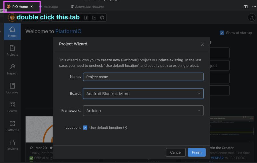
ConsThere was a small weird bug when creating a project. I couldn't enter the name on the Project Wizard window, because the project name field didn't allow me to type on it. I googled it and found a short term workaround, which is to double click on the PIO Home tab.
Option 3. VS Code & MicroPython & rshell
1) What is MicroPython
MicroPython is a tiny open source Python programming language interpreter that runs on small embedded development boards. With MicroPython you can write clean and simple Python code to control hardware instead of having to use complex low-level languages like C or C++ (what Arduino uses for programming). There are some unique features that set it apart from other embedded systems.
Interactive REPL (read-evaluate-print-loop): This allows you to connect to a board and have it execute code without any need for compilng or uploading.
Extensibility MicroPython is extensible with low-level C/C++ functions so you can mix expressive high-level MicroPython code with faster low-level code when you need it.
2) How to use
First, go to MicroPython.org and download a firmware corresponding to your board. I downloaded the ESP8266 firmware.
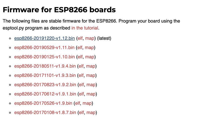
Then, I followed this tutorial.
pip3 install esptool
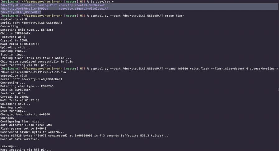
ls /dev/tty.* # get the USB port name (in my case, it was /dev/tty.SLAB_USBtoUART)
esptool.py --port /dev/tty.SLAB_USBtoUART erase_flash # clean out the board
esptool.py --port /dev/tty.SLAB_USBtoUART --baud 460800 write_flash --flash_size=detect 0 /Users/hyejinahn/Downloads/esp8266-20191220-v1.12.bin # deploy the firmware you downloaded to the board
Now you have MicroPython on your microcontroller.
You can test if it's really in it by typing the screen command.
      screen -port /dev/tty.SLAB_USBtoUART 115200

      >>> print("hello world")
      hello world
If you get Sorry, could not find a PTY. error message, you can fix it by going to Activity Monitor and terminating any "screen" processes.
Now it's time to install rshell, which is a remote shell for MicroPython. This is a simple shell which runs on the host and uses MicroPython's raw-REPL to send python snippets to the pyboard in order to get filesystem information, and to copy files to and from MicroPython's file system.
      sudo pip3 install rshell # install rshell
      rshell -p /dev/tty.SLAB_USBtoUART # to connect to your board
When I typed the last command, it kept giving failed to access /dev/tty.SLAB_USBtoUART error. I fixed it by killing the running process.
      lsof | grep "dev/tty.SLAB_USBtoUART" # grep the PID number of the process
      >> screen 47543 hyejinahn 5u CHR 9,346 0t3050 7411 /dev/tty.SLAB_USBtoUART

      kill 47543 # kill the process
      rshell -p /dev/tty.SLAB_USBtoUART # then run the rshell command again

    ls /pyboard # to see what's on ESP8266
    >> boot.py
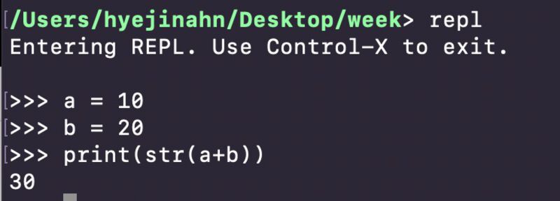
You can also type repl to get into the REPL environment. There, you can run code directly. Press control + x to get out of the repl.
I played with the an RGB LED on the breadboard with rshell. I could turn on and off the LED right away by typing command on the rshell.
You can also copy your Python program onto the board. This is a simple blink LED program I wrote.
      from machine import Pin
      import time

      counter = 5
      red_pin = Pin(16, Pin.OUT)
      green_pin = Pin(5, Pin.OUT)
      blue_pin = Pin(4, Pin.OUT)
      while( counter > 0):
      red_pin.off()
      time.sleep(0.5)
      red_pin.on()
      green_pin.off()
      time.sleep(0.5)
      green_pin.on()
      blue_pin.off()
      time.sleep(0.5)
      blue_pin.on()
      counter-=1
      print("done!")
I got out of the repl and copied this main.py file into the pyboard directory.
      cp main.py /pyboard/ # copy your file into the pyboard directory
      ls /pyboard # check if it's copied
      repl # open repl again
      import main # it will blink the LED
As soon as I imported the main.py, the LED started blinking. Awesome!
The main.py (the file name has to be main.py) file will be executed when you reset the board. If you press the reset key or plug on and off the cable, the LED will start blinking.
I also tried out ampy (Adafruit MicroPython tool). You can check out this link if you need some help on how to use ampy.
3) Pros and cons
Pros I think MicroPython is an good option if you already know Python well. Even if you don't know Python, it is still easier to learn than C or C++, so I think it's good for beginners who never programmed before.
Cons It was a lot of work to install MicroPython and other programs such as rshell and ampy. Also, there are not that many example codes or questions solved online. It's a lot more likely that you encounter a problem where you're the only one that had it, or at least the only one tried to search for it online.
Verdict
My favorite among the 3 options above was the Option 2. VS Code & C++ & PlatformIO.
My knowledge levels for C++ and Python are almost similar. So the fact that the Python language is more human readable doesn't really give me any advantage. The Option 3. VS Code & MicroPython & rshell option was also fun to try out. I liked rshell because I could interact with the board real-time. But, I didn't like that there were not that many code examples or trouble-shooting information for MicroPython online. I think this is the biggest downside when using MicroPython.
For the IDE, I like VS Code a lot more than Arduino IDE. It's partially because I'm used to it, since I've been using it for the past few years. With the PlatformIO package installed, VS Code can be much more powerful and easier to use than Arduino IDE. Arduino IDE lacks common text editor features such as autocomplete or multiple select which are very useful to help me save time.
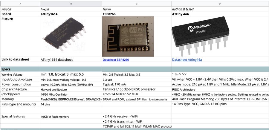
Group assignment
For this week's assignment, each of us read a datasheet of different boards (ATtiny1614, ATtiny44A, ESP8266) and compared the differences between them. Since I made a board with ATtiny1614, I read its datasheet and filled out the comparison form.
Also, we wrote down the development workflow for whatever architecture we chose.
- Microcontroller: ATtiny1614
- IDE: Arduino IDE
- Program download: UPDI, pyupdi library
- Communication: FTDI, miniterm
- Program I used in this example: Blink an LED when a button is pressed. And print out "BUTTON ON" and "BUTTON OFF" on the terminal screen.
More detailed documentation can be found on our group assignment page.