Final project
-
Final project - Smart miniature house
-
1. Principles and practices
-
2. Computer-Aided Design
-
3. COMPUTER-CONTROLLED CUTTING
-
4. 3D Scanning and Printing
-
5. Electronics design
-
6. INPUT DEVICES
-
7. OUTPUT DEVICES
-
8. Interface and application programming
-
9. Molding and casting
-
Bill of Material
-
Attachments
-
My Fab Academy journey
Final project - Smart miniature house
High quality version
Low quality version
Presentation
1. Principles and practices
Introduction
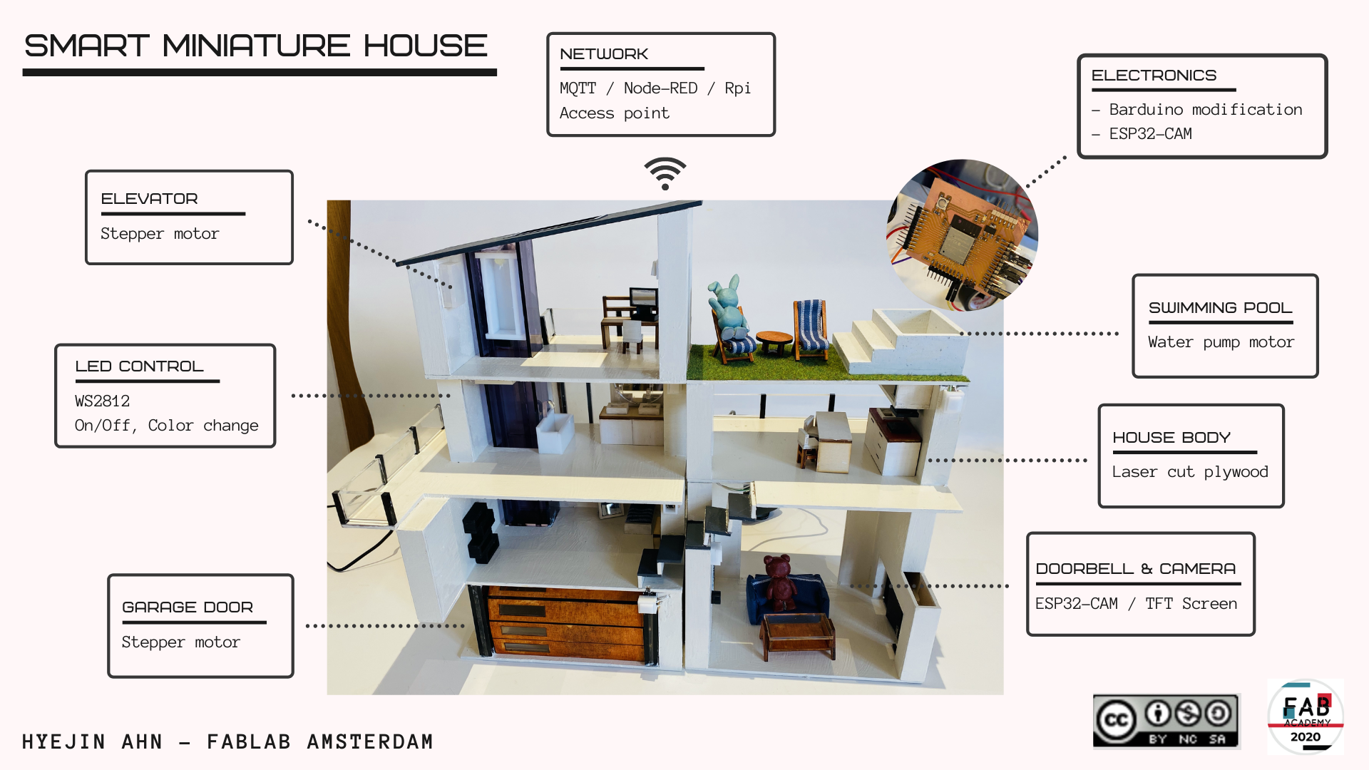
For the final project, I decided to make a smart miniature house. Several years ago, I made a miniature house with wood pieces from scratch. That was one of the most enjoyable experiences I can remember, I enjoyed doing every last step of that project, from designing the house to cutting wood pieces to putting them together. I thought it would be amazing if I could make a miniature house with automated and interactive features.
The first miniature house I made
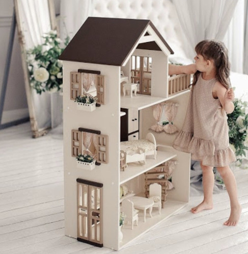
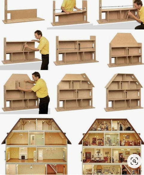
I thought about how big the house should be. It might be too hard to install all the electronics and wires if the house is too tiny. The houses in the images below would be the perfect size for the miniature house (around 100cm × 100cm).
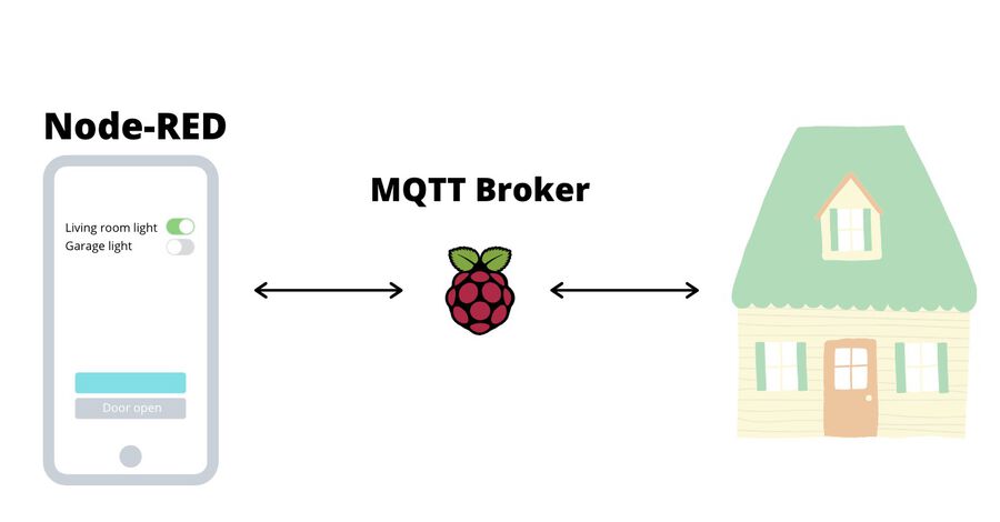
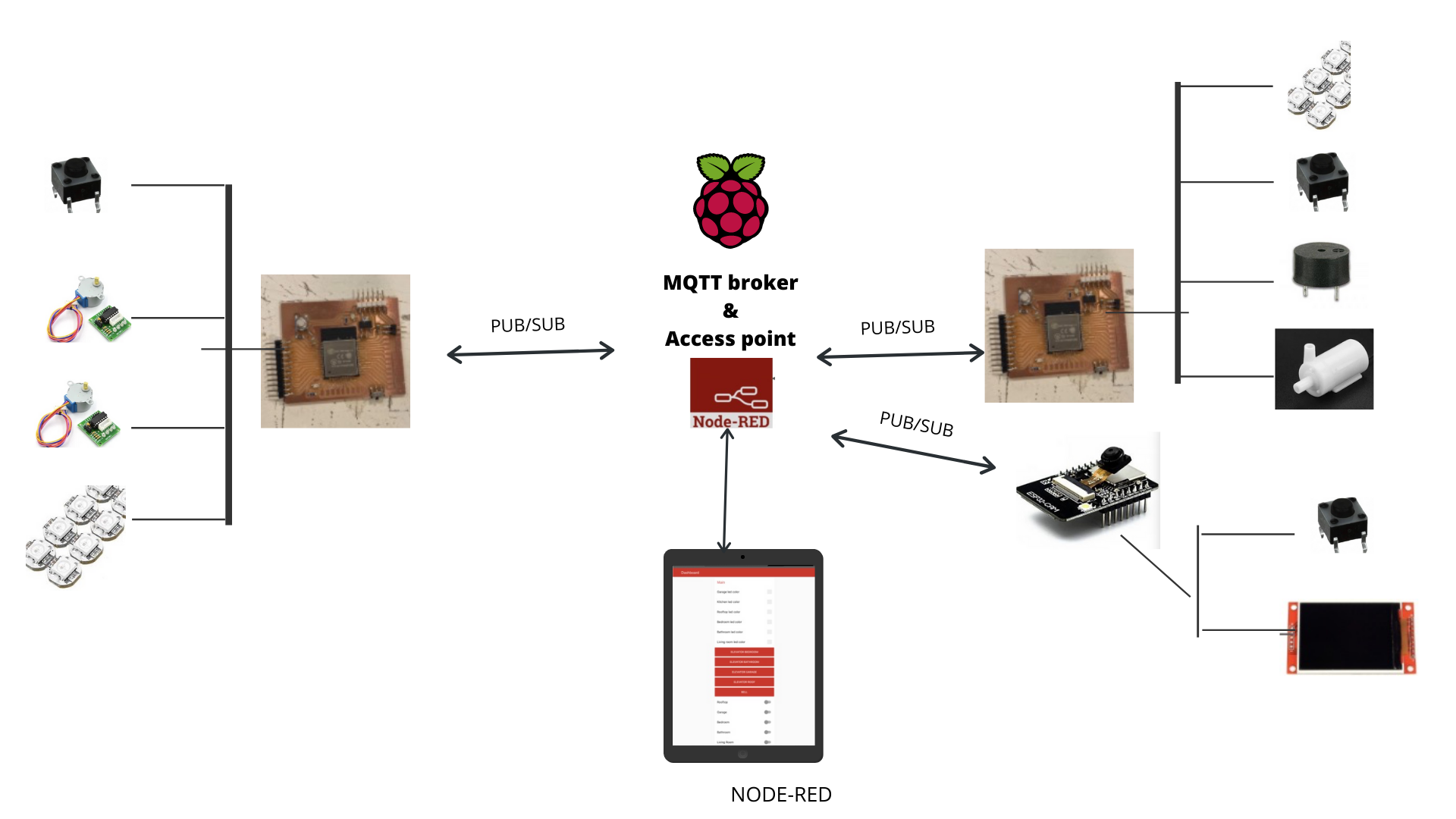
The house will be controlled both physically through buttons and remotely through MQTT communication. The MQTT broker will be run on a Raspberry Pi and I will make either a mobile or web app as a client.
Initial sketch
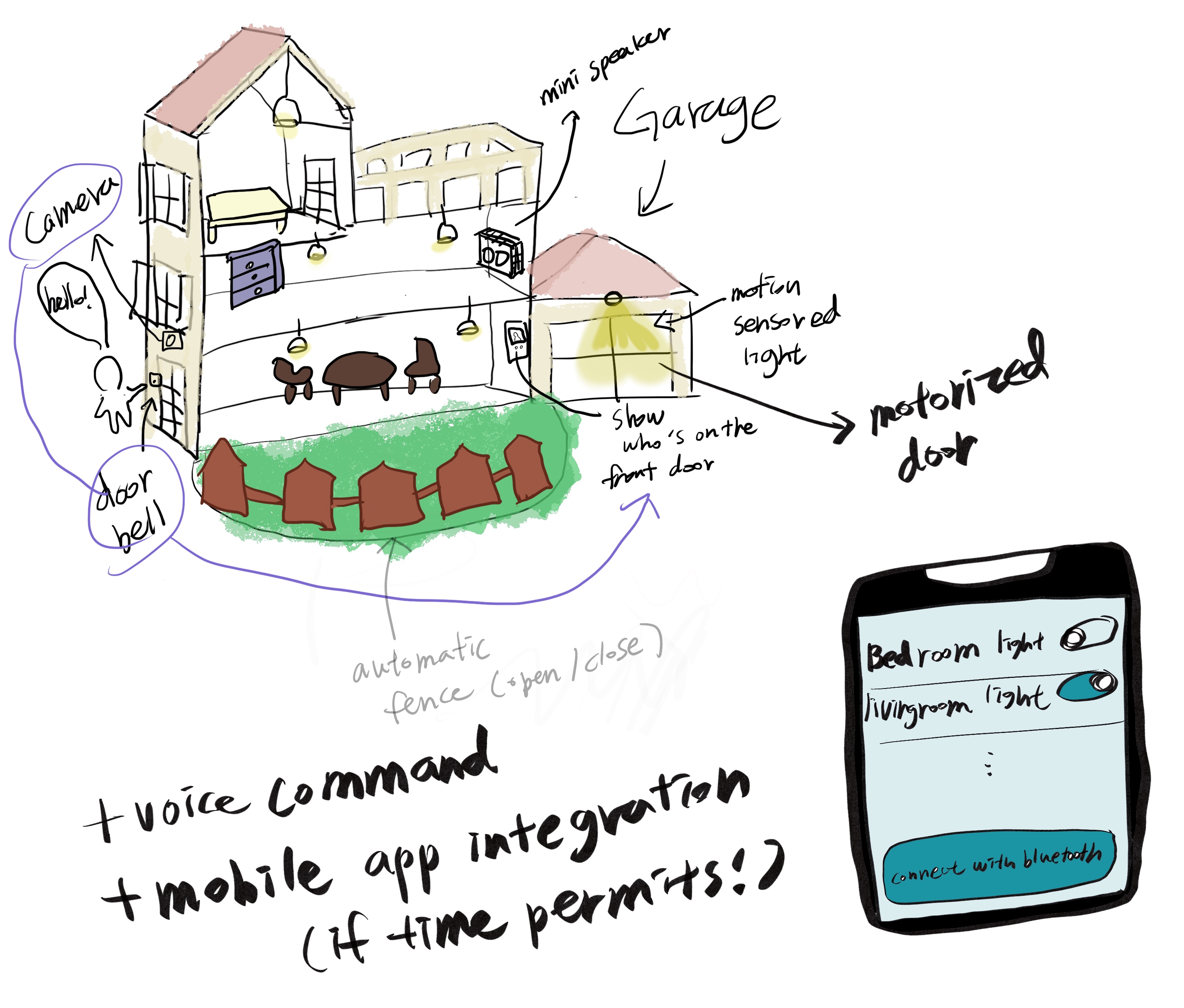
This is the first sketch I drew at the brainstorming stage. I added whatever that came to my mind at that time, so it might need to be whittled down later.
2. Computer-Aided Design
2D sketches
This is the sketch of my final project that I drew in Procreate.
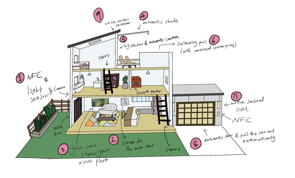
NFC lock, motion sensored light, doorbell and mini camera on the main door
Screen on the wall to see who's on the door when someone rings the doorbell
Photo frame on the wall - you can show your own image by connecting your phone through bluetooth
Automatic shade for the rooftop
Automatic curtain
Swimming pool water controlled with a water pump
Motion sensored light, NFC lock on the garage
Automatic garage door, the rail on the garage floor which pulls your car out of the garage
Control with an app
Light control (color, brightness)
Elevator
3. COMPUTER-CONTROLLED CUTTING
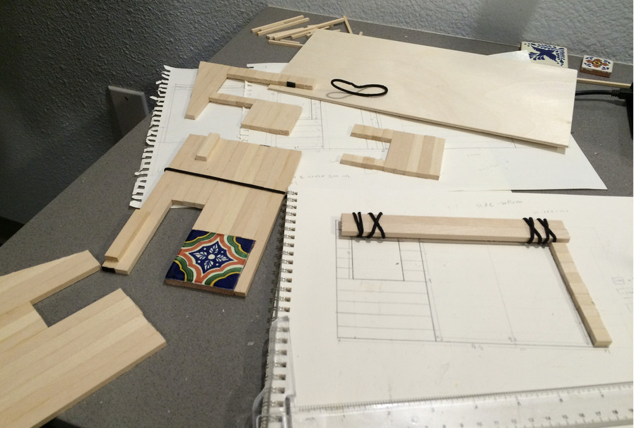
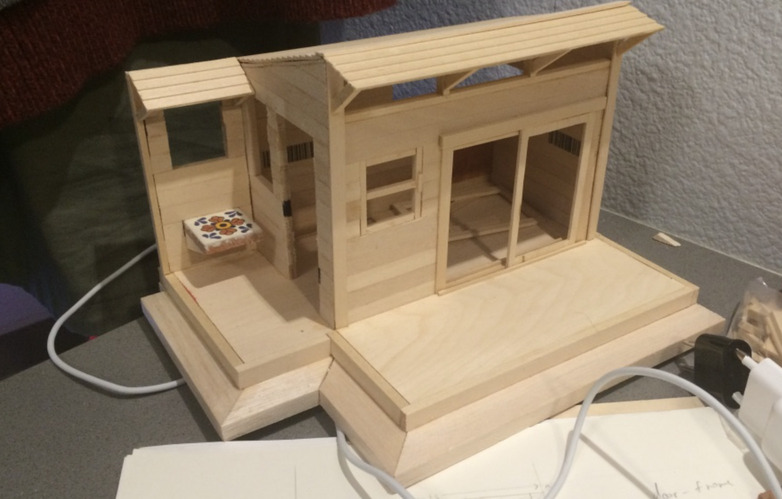
Foam board house
During the break week, I used some foam boards and acrylic sheets to make a house I designed. We couldn't use the machines at the lab because of the Coronavirus, so I had to cut the board by hand.


The foam board house helped me to figure out some concerns I had, such as how big the house should be and where to place the electronic components.

I wanted to make the house foldable like above, but this part was tricky to design on Fusion 360 because of the lack of my skill. But with the foam boards, I could experiment with different designs and measurements and see if they really fit together. After some trial and error, I finally made them fit together and I revised the design on Fusion 360.
Cardboard house
In June, the lab finally opened for the students. As soon as I got access to the laster cutter machine, I used the machine to cut the house body design I've been working on. I used the 3mm thick cardboards and it was very sturdy.


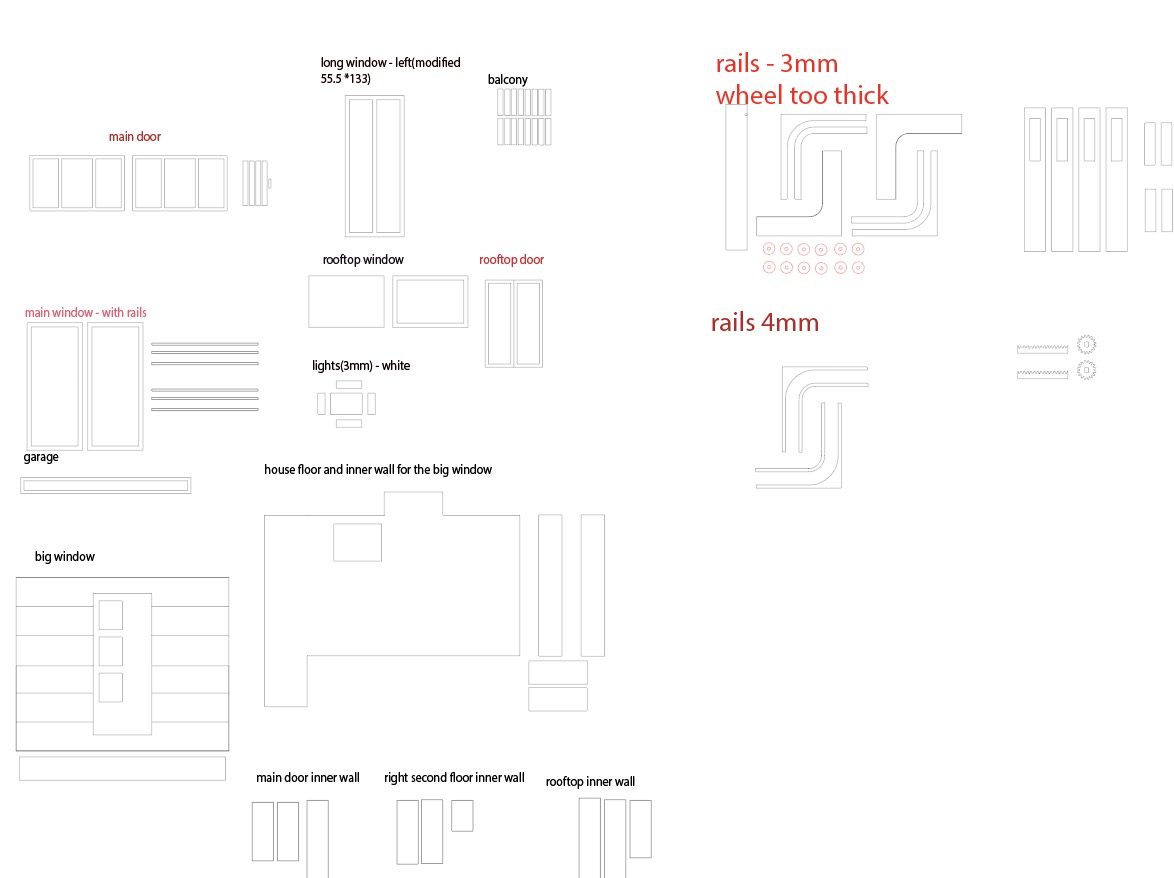
I moved the floor plan to the Adobe Illustrator and cut them with the laser cutter. I really thought that everything was perfectly measured, but there were some mistakes, such as the length or design of the components. After changing and updating the design, I finally finished the house body. The final step will be cutting them on wood boards.


Plywood house
After finishing testing my house design with the cardboard, I finally printed them out on a plywood.

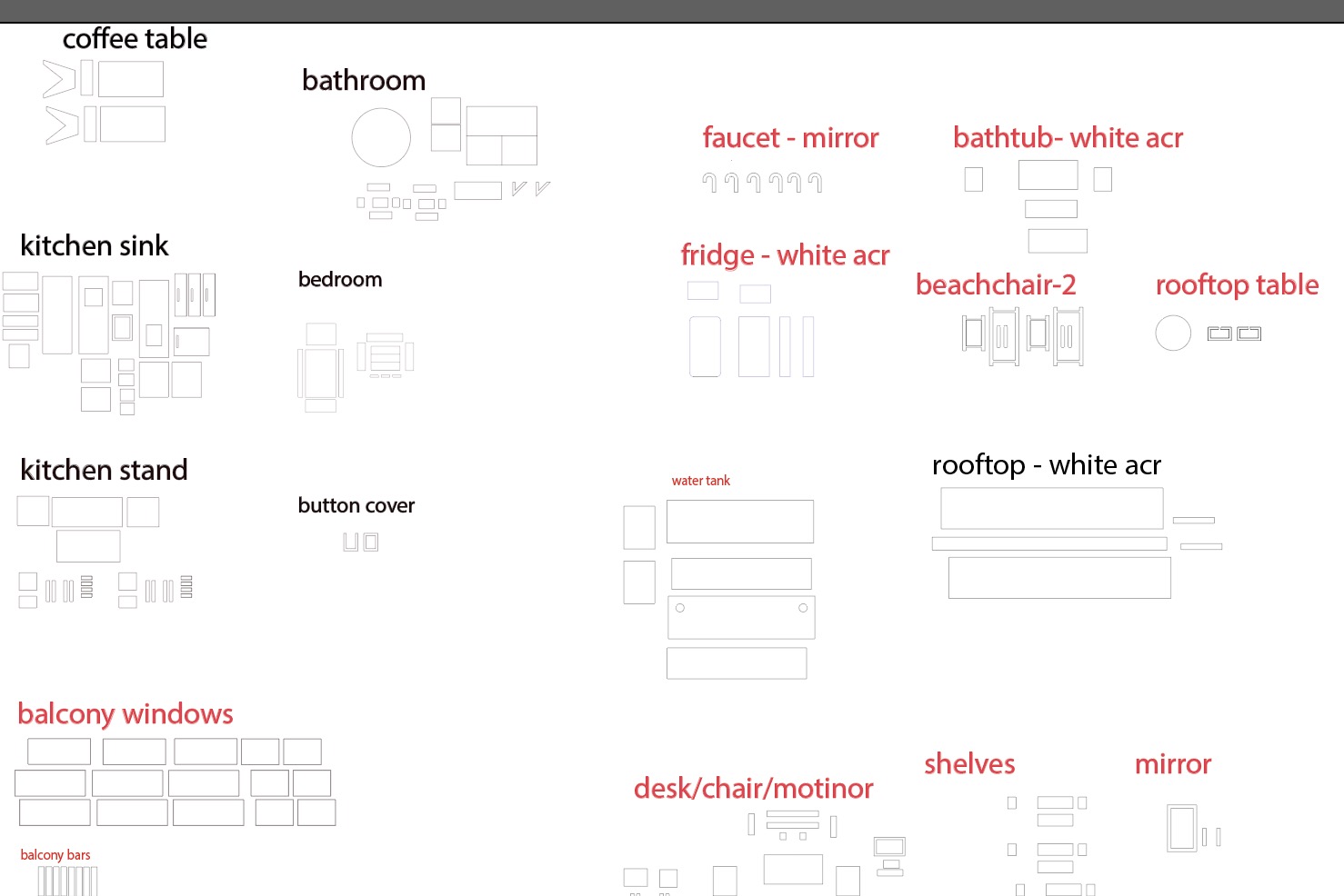
Also I made a design for the furniture and windows for the house, and cut them with the laser cutting machine. Then, I painted them with acrylic paint.
The result looked great!

3D sketches
For 3D rendering, I used Fusion 360.

House Version 1

House Version 2
House Version 1.1
I've designed several houses so far, and I decided to use the Version 1.1 house for my final project. I also like the Version 2 one, because I got the house design from the movie Parasite. But since it has a horizontal layout, it might be hard to integrate the features I want.
4. 3D Scanning and Printing
3D printing
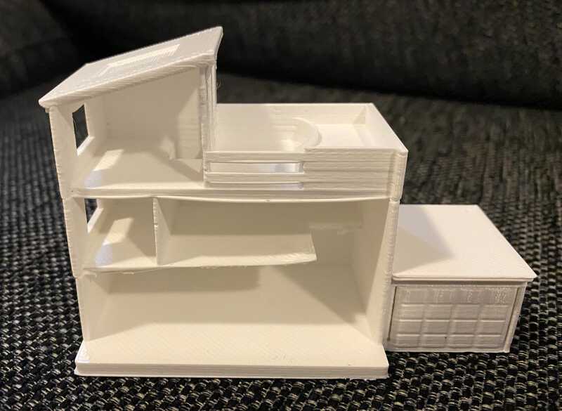
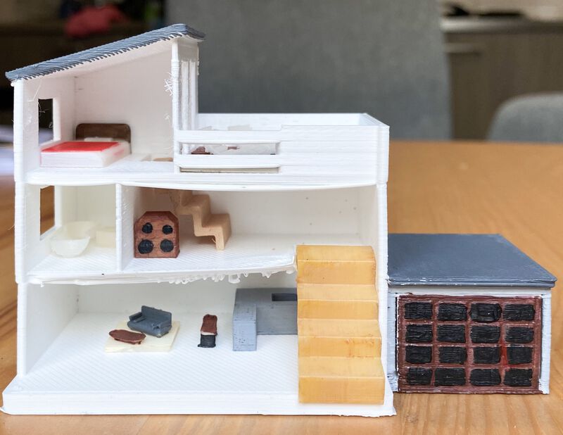
One of the assignments in week 6 was to design and 3D print an object. At first, I was going to design a new object for this assignment. Then I realized that I have the 3D designed houses that I made on week 3. I decided to print out the first house I made because it looked simpler than the Parasite house. I separated the house body and furniture and exported them into each file. It felt like moving day :P

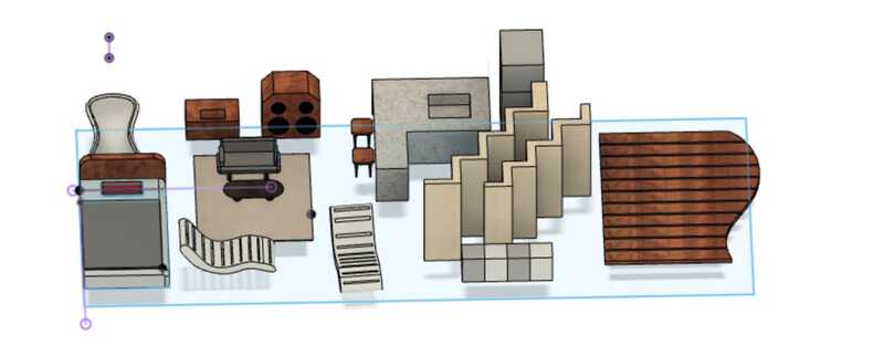
Here is the 3D-printed super miniature house and furniture. They were so tiny and cute.
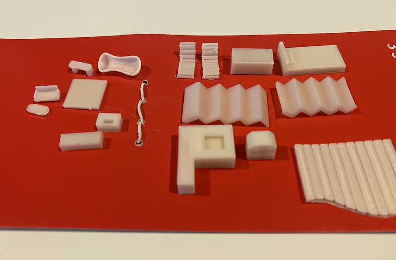
I bought acrylic paint from the art supply store and painted them one by one. It wasn't easy, but the result was quite satisfying.

5. Electronics design
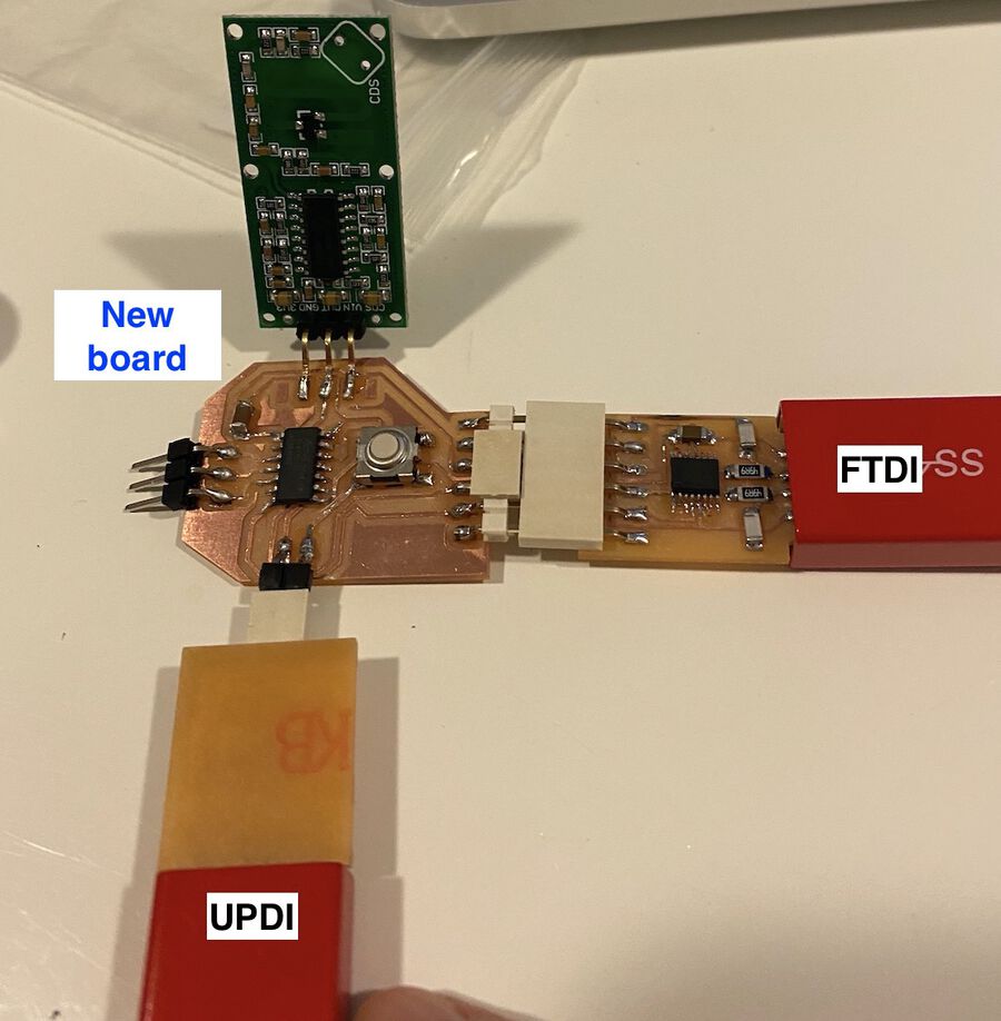
Design my first PCB board
On week 7, I made the first PCB board with an ATtiny1614 microcontroller. I used KiCad to design the board. I failed three times for different reasons, but I learned a lot from each mistake.
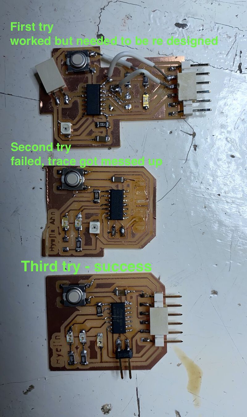
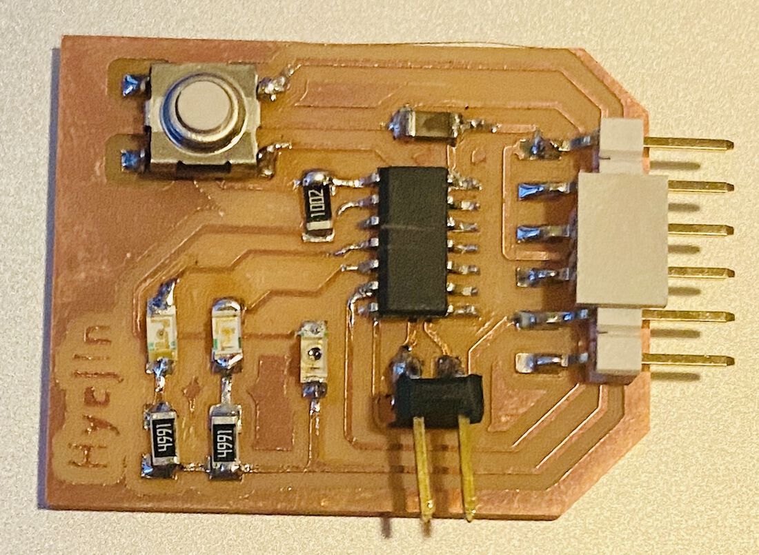
I used an FTDI board to download the communicate into my board, and used a UPDI board to program with the board. The program I wrote was pretty simple. When you press the button, the LED blinks really fast and it stops when I let go of the button.
Barduino modification
For the final project, I decied to use the Barduino board. I made some modifications on it.
The modified barduino Kicad file can be found here.
There are 2 barduinos used in my final project. One is for the right part of the house and the other one is the left part of the house.


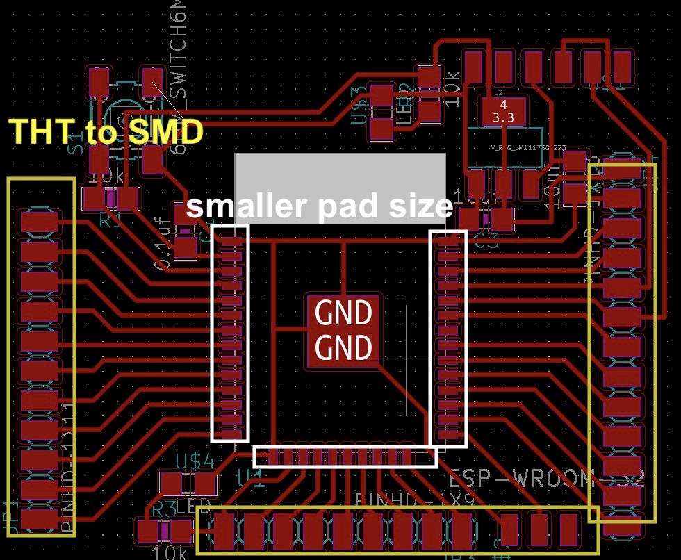
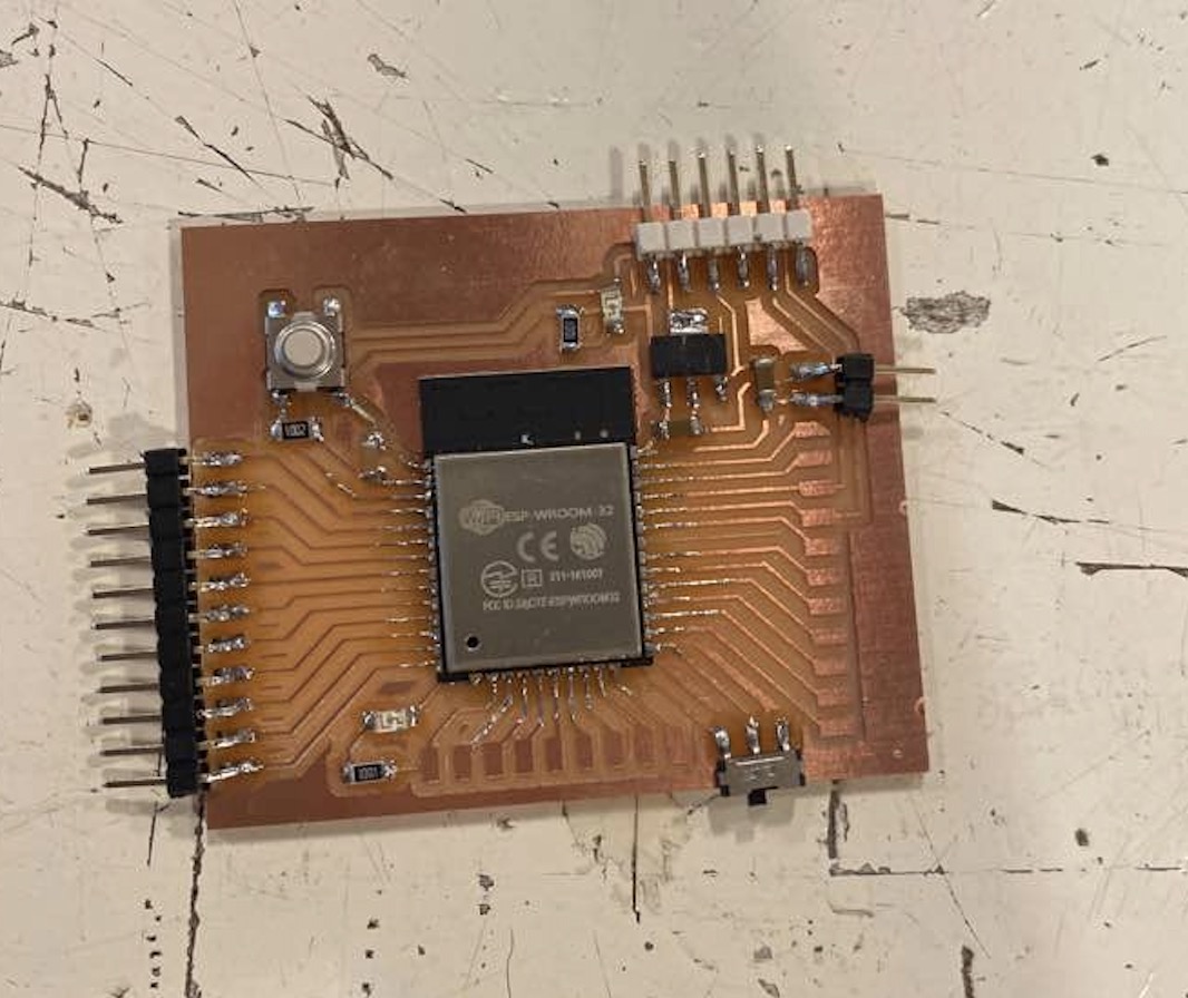
6. Input devices
Use a sensor and camera module
From what I learned for the last several weeks, I made a new board with an ATtiny1614 chip and connected it with an RCWL-0516 sensor. I also programmed an ESP32-CAM module so that I could see the object approaching the sensor. Lastly, I made a PyQT program to show the data on the computer screen.
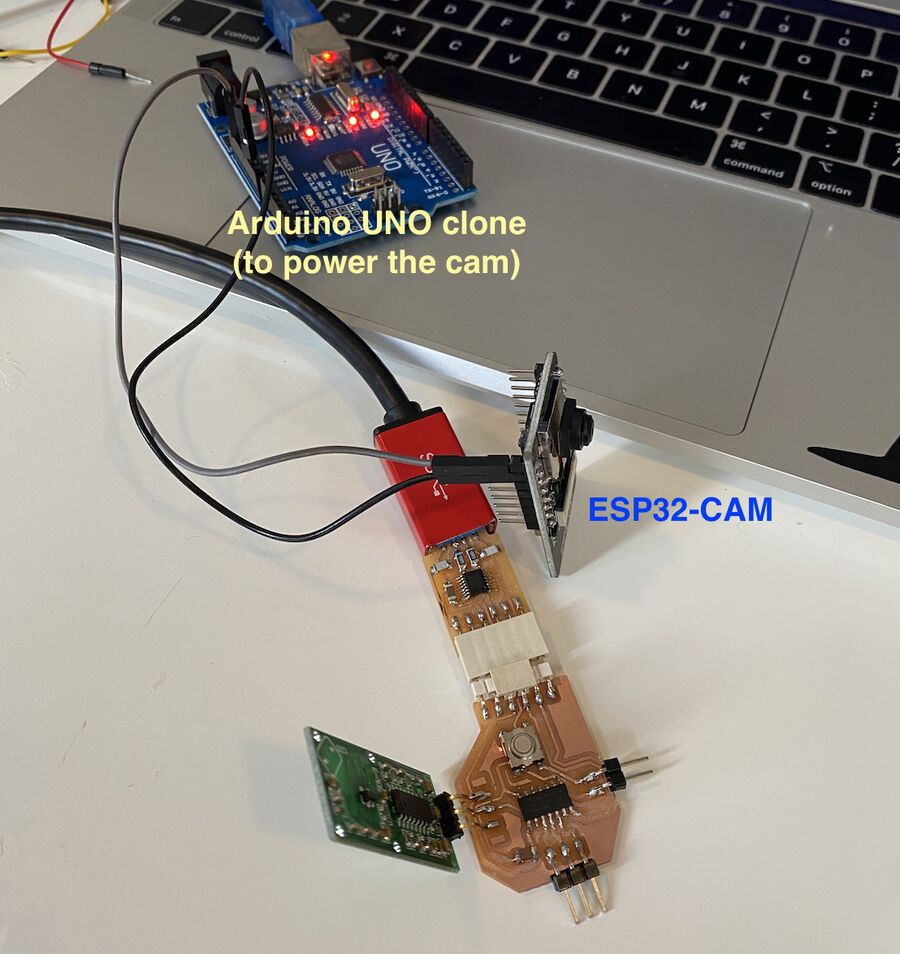
Then, I set up the ESP32-CAM module powered with an Arduino board next to the new board.
In the PyQt program, the ESP32-CAM shows the live video while the RCWL-0516 sensor collects the movement data. If I move my hand towards the RCWL-0516 sensor, it prints 1 and changes the square color to red. And if I let my hand stay still, it prints 0 and changes the square color back to grey.
I placed the ESP32-CAM in between the house wall like the photo below and powered it with the 5V power supply.

7. OUTPUT DEVICES
On the output devices week, I made an elevator and an automated garage door with a 28BYJ48stepper motor. It worked well in general, but I think I should consider using a stronger stepper motor than this one for the final project.
Stepper motor test 1. Elevator
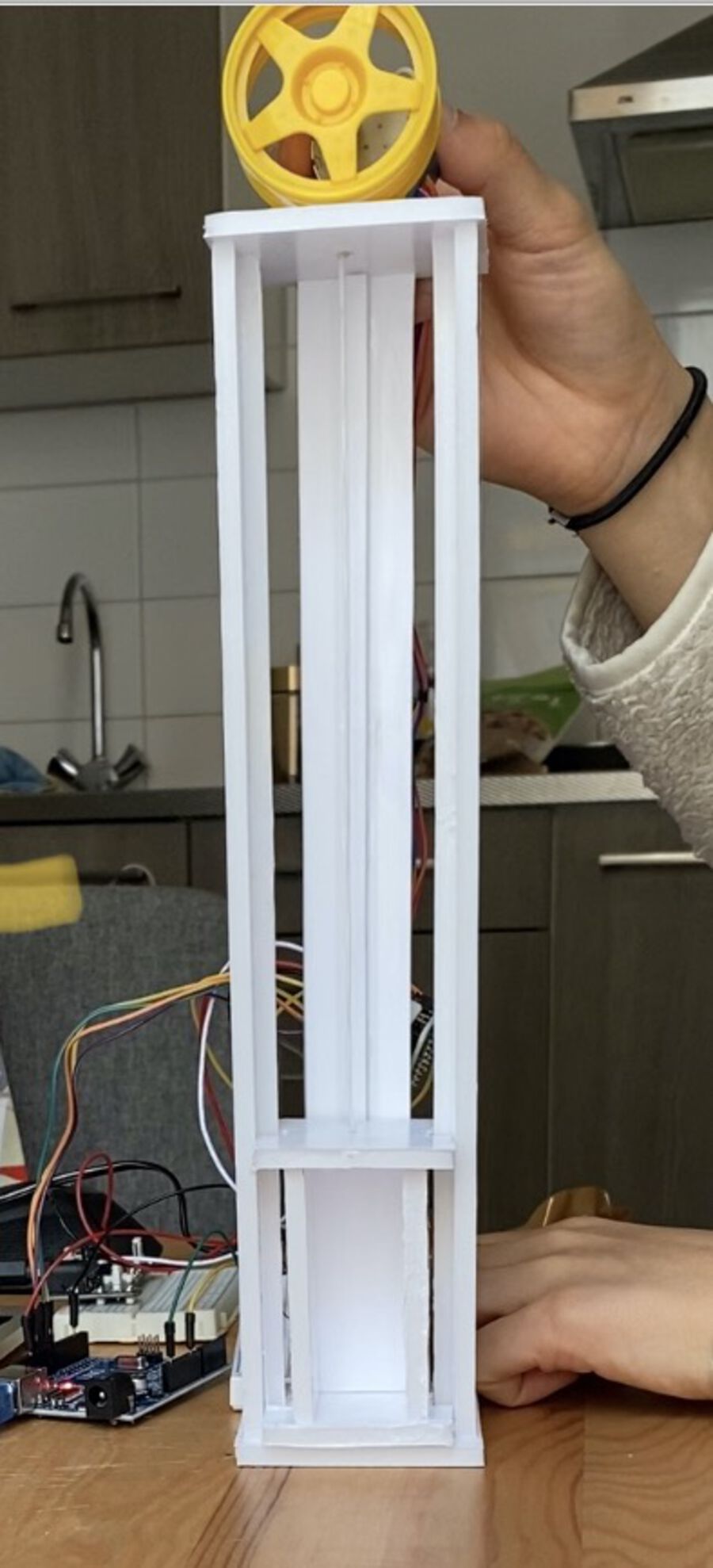
The photos above are the design on Fusino 360 and the model I made with some foam boards. There's a string attached to the elevator and I connected the stepper motor to it. Also, I added buttons like the real elevator so that I could go to the each floor.
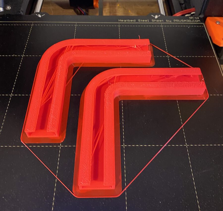
Stepper motor test 2. Garage door
This week, I also designed a simple garage and the door with rails. Since our lab was still locked down, our instructor, Henk, 3D-printed the rails on my behalf :). I bought other materials from a hardware store nearby. Like the elevator, I made the outside body of the garage with the foam board.
The code for the garage isn't that different from the elevator one. I will use either a hall effect sensor or limit switch for homing the garage door same as the elevator. The video below is also 3 times sped up since the motor went really slow. It's hard to see on the video, but the motor is on the back side of the object. I couldn't fixate it so I had to hold it while taking the video.
This is how I put the stepper motor and the driver in my final project.

8. Interface and application programming
This week's individual assignment is to write an application that interfaces a user with input/output devices I made. For the last several weeks, I’ve been playing around with ESP32-CAM, an RGB LED and a TFT LED display. I set this week’s goal to control them by using the MQTT protocol combined with Node-RED.
MQTT & Node-RED
I didn't use NodeMCU in my final project. I didn’t use nodemcu for the final project. That was from weekly assignment
I wanted to put a camera in front of the door. That would transmits images to the LCD screen inside of the house, when someone pressed the doorbell. And the buzzer will ring when the doorbell is pressed. Also, I wanted to control an RGB LED through Node-RED and MQTT.
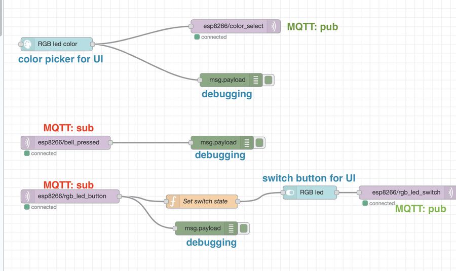
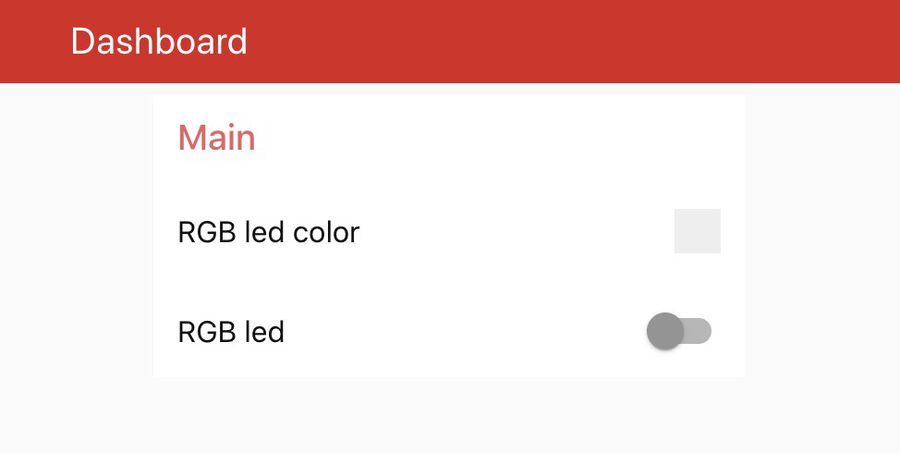
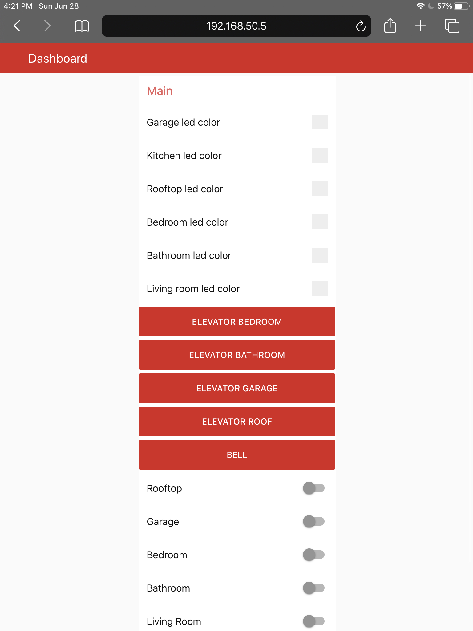
The photo on the left is the flow I created and on the right one is the UI. I also added some debugging nodes so that I could see the message coming through the MQTT. Also, it subscribes to the LED button pressed and the doorbell pressed topic. When the LED button is pressed, it updates the state of the switch on the UI so that there's no mismatches between them. Also when the doorbell is pressed, the buzzer connected to the NodeMCU will buzz because it's subscribing to that topic.
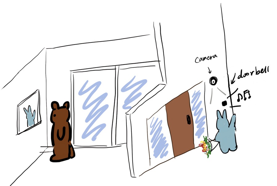
When the push button is pressed, the camera gets awake from the idle mode (the bear paw image), and it shows the images sent from the ESP32-CAM.
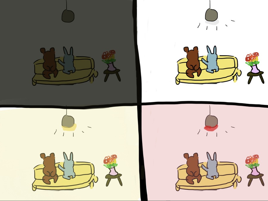
You can turn on and off the light and change the color of it from the Node-RED UI. Also, when you press the push button, the switch on the UI will be updated as well.
Updates - June 28th
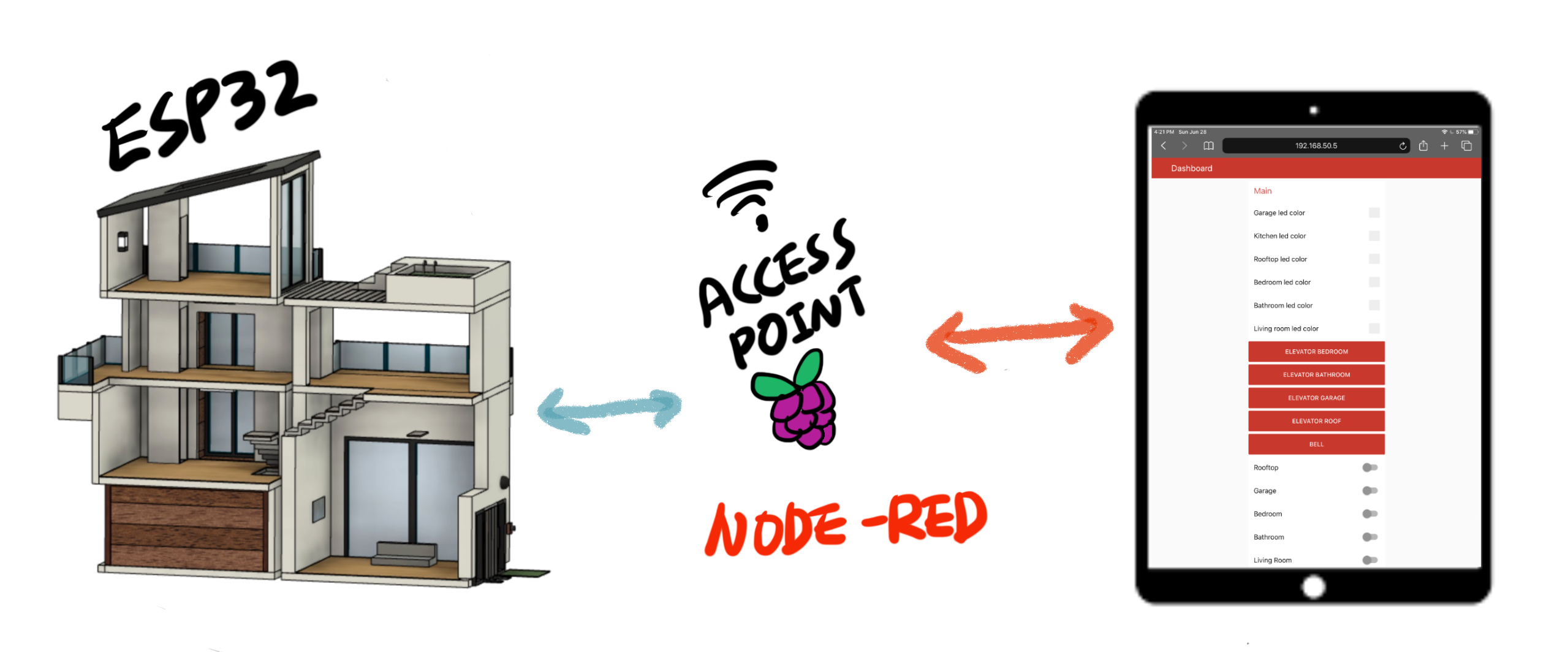
Instead of connecting the ESP boards and RPi to the home WiFi, I made them connceted to the access point of the Raspberry Pi. I followed these instructions and it worked well. Every ESP32 boards are connected to the RPi, and I can access to the Node-RED running on the RPi by connecting my device to the access point and control the house from this UI.
9. Molding and casting
Swimming pool
I decided to make a swimming pool with cement because I liked the cement finish texture. To do this, I first designed a swimming pool with Fusion 360. Then, I printed it out with the Ultimaker 3D printer and set a wall around it to pour silicon in it. I used the Mold star 30.


The next day, the mold was ready to go. I mixed the cement and pour it into the mold. I love molding and casting so much :D


And this is the final result of the swimming pool with cement.

The design file for the swimming pool can be found here.
Bill of Material
| Material | Quantity | Price |
|---|---|---|
| Stepper motor & Stepper motor driver(28BYJ-48, ULN2003) | 2 | €4.95 |
| Water pump(JT-DC3W-3) | 1 | €2,18 |
| ESP32-CAM | 1 | €9.99 |
| TMB12A05 buzzer | 1 | €1,13 |
| 2.2" Color TFT LCD Display Module | 1 | €13,29 |
| ESP-WROOM-32 | 2 | €1,60 |
| Plywood | - | €4,67 per m2 |
| 3mm Acrylic board | - | €11 |
| Wood varnish(Sencys vernis zijdeglans teak 500ml) | 1 | €11,19 |
| Wood paint primer(Perfection Grondverf Superdekkend Wit 0,375L) | 1 | €7,19 |
| Wood paint(Flexa Strak In De Lak Hoogglans Gebroken Wit Ral 9010 250 ML) | 1 | €8,69 |
| 1*5 header | 3 | €0.33 * 3 |
| Push button(RND 210-00204) | 10 | €0.21 * 10 |
| Voltage Regulator - 3.3V - COM-00526 | 3 | €0.56 * 3 |
| 10k resistor | 4 | €0.01 * 4 |
| 1k resistor | 4 | €0.01 * 3 |
| 0.1µF capacitor | 4 | €0.12 * 3 |
| 10µF capacitor | 4 | €0.18 * 3 |
| WS2812 | 1 | €18.95 |
| Raspberry pi 4 Model B | 1 | €39 |
| Smooth-Cast 325 | 1 | €31 |
| Aalborg Portland cement 25 kg wit | 1 | €14 |
| 10W 5V2a (2000mA) power supply | 2 | €14 |
My Fab Academy journey
Flow state: In positive psychology, a flow state, also known colloquially as being in the zone, is the mental state in which a person performing an activity is fully immersed in a feeling of energized focus, full involvement, and enjoyment in the process of the activity.
I have been in a flow state for the last 6 months in this Fab Academy journey. I was fully immersed when I was making something every week, without noticing the time passing. It feels weird to be in a void where used to be filled with all the confusion, knowledge, stress, and enlightenment. I learned a lot from this course, not only how to make stuff but also how much I love making and how much joy it brings to my life. Now, when I see my surroundings, I can see through how things were made. It's not in the mystery anymore and I'm confident that I can make one like that or even better than that. As a person who is living in the 21st century where almost everything is made from the factories across the world and we became merely consumers of those products. The Fab Academy means a lot to me in the sense that I no longer a passive consumer but a maker who can also make something and add value to this world. (I still have to learn how to fix a flat tire as a resident of the Netherlands 😉) Thank you for everyone who has been supporting and helping me throughout the course. I will miss everyone and this time journey be remembered forever in my life.