-
01. Principles and practices
-
02. Project management
-
03. Computer-Aided design
-
04. Computer controlled cutting
-
05. Electronics production
-
06. 3D Scanning and printing
-
07. Electronics design
-
08. Computer controlled machining
-
09. Embedded programming
-
10. Input devices
-
11. Applications and implications
-
12. Output devices
-
13. Interface and application programming
-
14. Invention, intellectual property and income
-
15. Networking and communications
-
16. Molding and casting
-
17. Wildcard week
-
18. Machine design
-
19. Project development
-
Glossary
Week 15. Networking and communications
May 13, 2020
Assignment
Group assignment
- Send a message between two projects
Individual assignment
- Design, build, and connect wired or wireless node(s) with network or bus addresses
Individual assignment
Overview
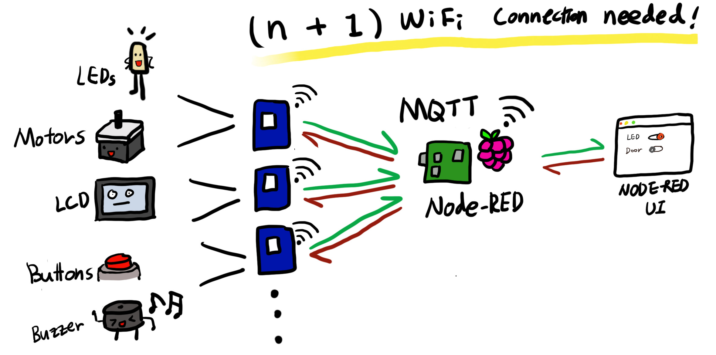
My main focus this week was the NRF24L01 transceiver module. Before starting to explain what I did with NRF24L01, I want to explain why I used it. For the last several weeks, I've been using WiFi modules (ESP32, ESP8266) to connect the boards through the MQTT broker. But I realized that whenever the WiFi environment changes, I need to set up the new WiFi credentials for every single WiFi module. That also means I have to make sure that each WiFi module is connected to the WiFi. The Raspberry Pi also needs to be connected to WiFi, because of the MQTT broker running on. Which means, N (the number of WiFi modules) + 1 WiFi setup and maintenance would be needed for this project.
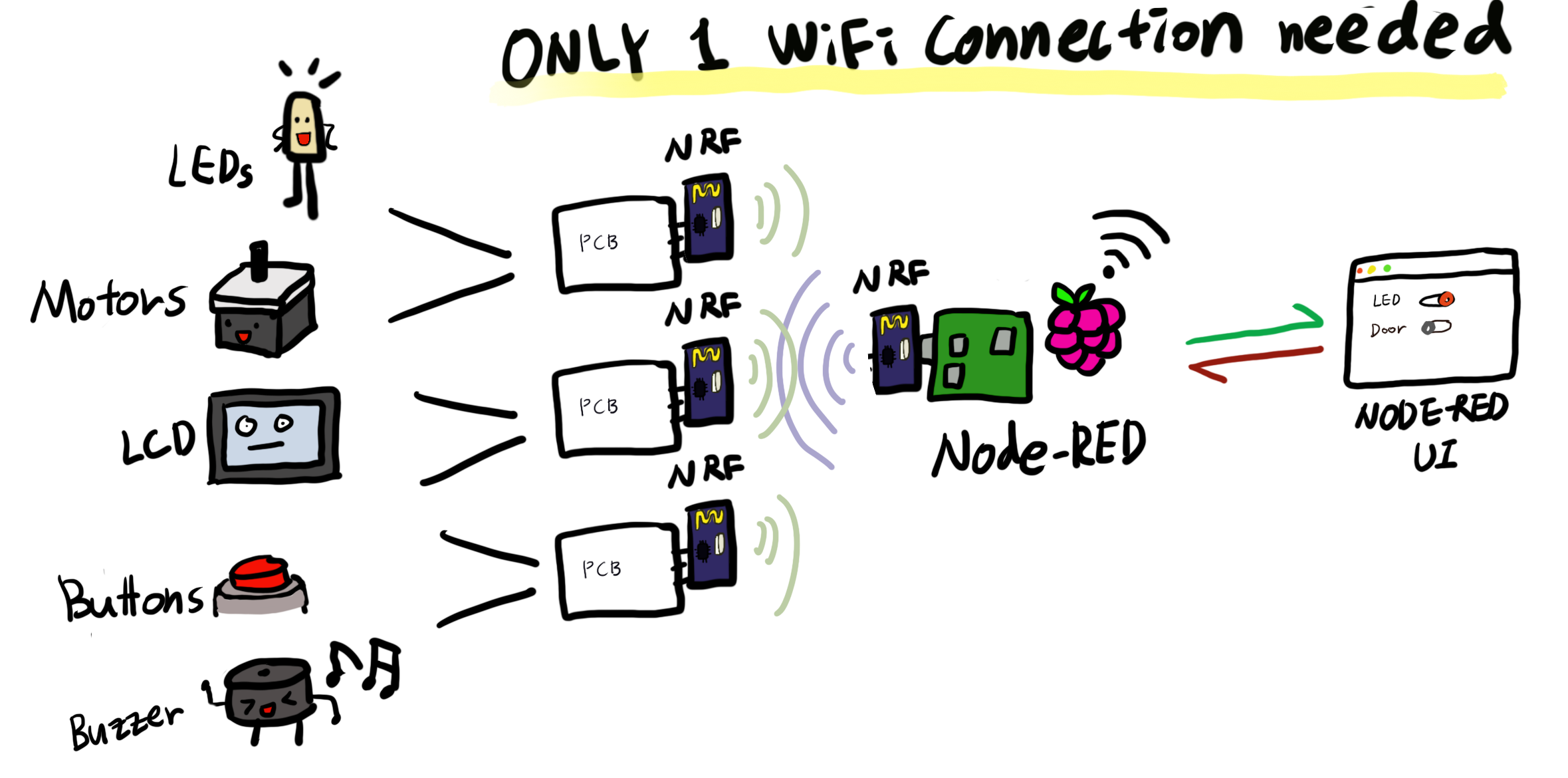
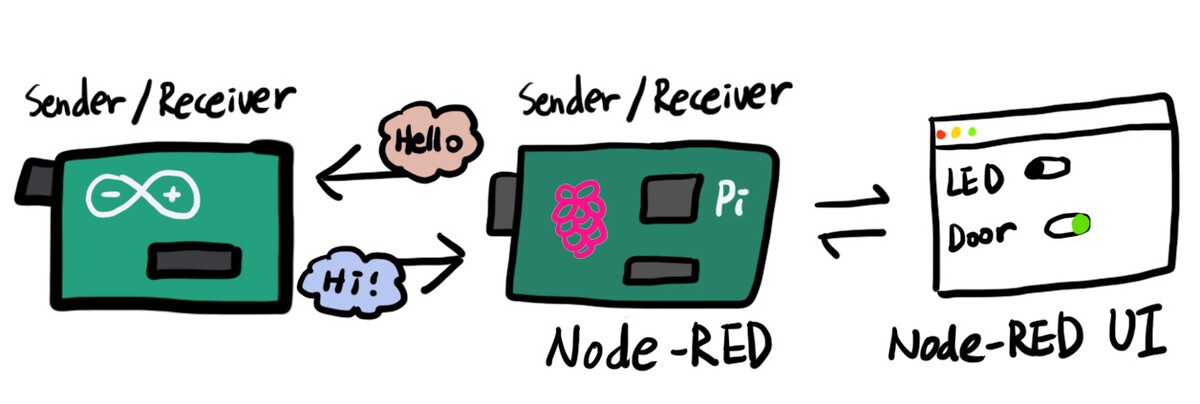
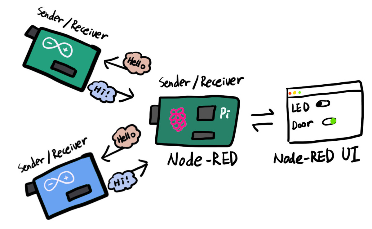
That's why I decided to use the NRF24L01 instead of the ESP32 or ESP8266. I will add the NRF24L01 to the boards with output/input devices, and this will talk to the NRF24L01 attached to the Raspberry Pi, which has Node-RED running on it. This way, only one WiFi connection (for the Raspberry Pi) will be needed for the entire project.
This week's assignment was the hardest one so far. I spent a lot of time trying to understand the basic network knowledge. There were a lot of obstacles while working on the project, but I was able to break through most of them with the help of my boyfriend.
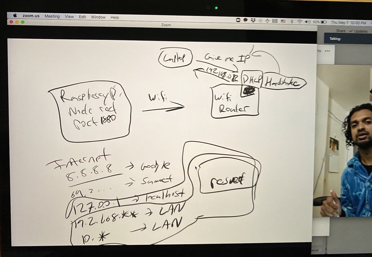
My boyfriend explaining network stuff on Zoom :D
nRF24L01+ transceiver module
1) Overview
- Radio Frequency: Designed to operate in 2.4 GHz worldwide ISM frequency band. The data transfer rate can be one of 250kbps, 1Mbps and 2Mbps.
- Power consumption: The operating voltage of the module is from 1.9 to 3.6V, but the good news is that the logic pins are 5-volt tolerant, so we can easily connect it to an Arduino or any 5V logic microcontroller without using any logic level converter.
- SPI Interface: Communicates over a 4-pin Serial Peripheral Interface (SPI). All the parameters such as frequency channel, output power , and data rate can be configured through SPI interface.
2) nRF24L01+ Multiceiver Network
What interests me most about this module is the Multiceiver (Multiple Transmitters Single Receiver) network feature. The primary receiver acts as a hub receiver collecting information from 6 different transmitter nodes simultaneously. The hub receiver can stop listening any time and acts as a transmitter. But this can only be done one pipe/node at a time.
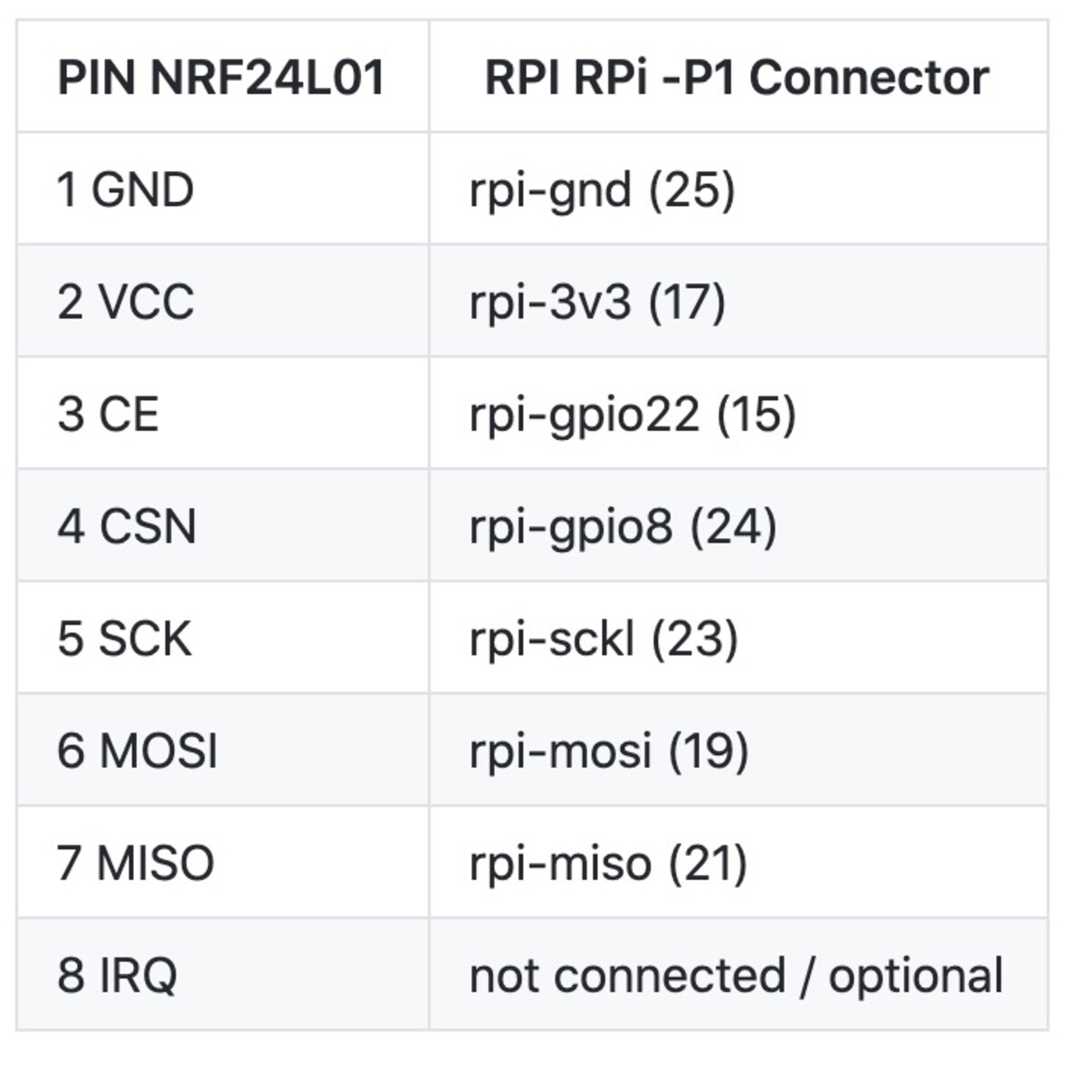
3) Pinout
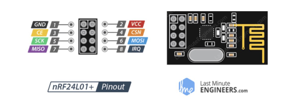
GND is the Ground Pin. It is usually marked by encasing the pin in a square so it can be used as a reference for identifying the other pins.
VCC supplies power for the module. This can be anywhere from 1.9 to 3.9 volts. You can connect it to 3.3V output from your Arduino. Remember connecting it to 5V pin will likely destroy your nRF24L01+ module!
CE (Chip Enable) is an active-HIGH pin. When selected the nRF24L01 will either transmit or receive, depending upon which mode it is currently in.
CSN (Chip Select Not) is an active-LOW pin and is normally kept HIGH. When this pin goes low, the nRF24L01 begins listening on its SPI port for data and processes it accordingly.
SCK (Serial Clock) accepts clock pulses provided by the SPI bus Master.
MOSI (Master Out Slave In) is SPI input to the nRF24L01.
MISO (Master In Slave Out) is SPI output from the nRF24L01.
IRQ is an interrupt pin that can alert the master when new data is available to process.
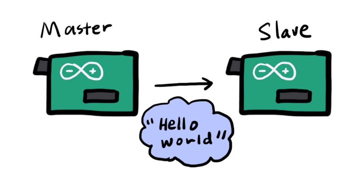
Step 1. RF communication between Arduinos
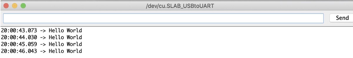
I started with testing a simple master-slave RF communication between two Arduinos. One of them acts as a master, and the other one acts as a slave. The master sends the text data Hello World, and the slave listens to it and prints out the text to the serial monitor.
Connecting the nRF module and Arduino was quite a work. I had to make sure to connect each pin correctly, but it was really confusing. I had to look at the pinouts of both nRF24 and Arduino. I connected them like below. It's for an Arduino Uno board, so if you are using anything other than Uno, You have to check the pinout of the board. CE and CSN can be connected to other pins, but you have to update the pin numbers in the code files accordingly. You also have to download the RF24 library to the Arduino IDE. The example code was from here.
- GND: GND pin
- VCC: 5V
- CE: Pin 7
- CSN: Pin 8
- SCK: Pin 13
- MISO: Pin 12
- MOSI: Pin 11
Code for the master Arduino
#include <SPI.h>
#include <nRF24L01.h>
#include <RF24.h>

RF24 radio(7, 8); // CE, CSN

const byte address[6] = "00001";

void setup() {
  radio.begin();
  radio.openWritingPipe(address);
  radio.setPALevel(RF24_PA_MIN);
  radio.stopListening();
}

void loop() {
  const char text[] = "Hello World";
  radio.write(&text, sizeof(text));
  delay(1000);
}
Code for the slave Arduino
#include <SPI.h>
#include <nRF24L01.h>
#include <RF24.h>

RF24 radio(7, 8); // CE, CSN

const byte address[6] = "00001";

void setup() {
  Serial.begin(9600);
  radio.begin();
  radio.openReadingPipe(0, address);
  radio.setPALevel(RF24_PA_MIN);
  radio.startListening();
}

void loop() {
  if (radio.available()) {
    char text[32] = "";
    radio.read(&text, sizeof(text));
    Serial.println(text);
  }
}
The code worked well, so I moved to the next step, which was setting up the Raspberry Pi to make it communicate with the Arduino through nRF24L01.
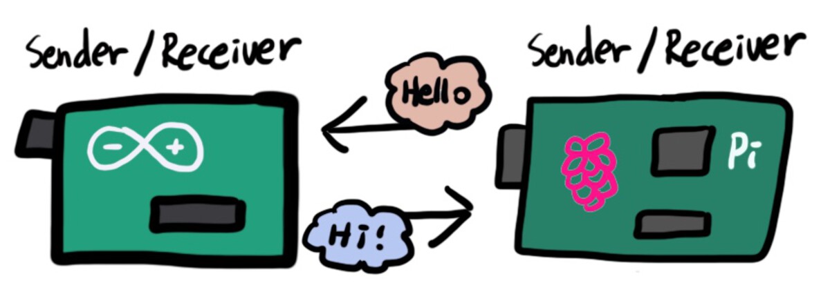
Step 2. RF communication between Arduino and Raspberry Pi
The next mission was to communicate between the Raspberry Pi and Arduino. In this step, I wanted to make a two-way communication unlike the one-way communication in the previous step.
I was planning to use node-red-contrib-nrf24, and it asked me to check the prerequisites of nRF24 from here. I went to that page, and followed the instructions written on that page.
Instruction 1. SPI enabled & Gpio Access
In order to communicate with the radio, the Linux kernel needs to have SPI enabled and direct access to board GPIOs. I typed raspi-config on the terminal of the Raspberry Pi and selected Interface Options. Then, selected SPI and enabled it, and rebooted the Pi. If you don't know how to do it, this link will help.
Instruction 2. User & Group check
I'm not sure if this step does anything. When I first tried to use RF24 nodes for Node-RED, it kept giving me the rf24 not working or in use error message. I read the instructions again and decided to try this step which I ignored before.
Gpio access require access to sysfs under the path /sys/class/gpio/. In common linux distributions simply adding the user executing the nodejs application to the gpio group check usermodto do it.
I changed the user and group to root. It's for using Node-RED later, so if you are not going to use Node-RED, you can skip this instruction. The node for RF24 didn't work right away even after I made this change, but it started working at some point after rebooting and re-installing the library. I still don't know if it did anything, but I don't want to mess around with it since it's working now.
pi@raspberrypi:~ $ ps auxwww | grep -i node
root      1346 52.5  7.1 159600 67952 ?        SNsl 19:06   0:08 node-red
pi        1385  0.0  0.0   4344   528 pts/0    S+   19:06   0:00 grep --color=auto -i node
Instruction 3. Connect the Pi and Arduino
Next, I connected the Pi and nRF module like below.
Step 4. RF24* libraries installed
The instructions asked me to check if the RF24* libs was installed. To install them, I went to this link and followed the instructions on the page.
wget http://tmrh20.github.io/RF24Installer/RPi/install.sh # Download the install.sh file
chmod +x install.sh # Make it executable
./install.sh  # Run it and choose your options. I said Y to everything
cd rf24libs/RF24/examples_linux # Go to the example folder
nano gettingstarted.cpp # You need to dit the gettingstarted example, to set your pin configuration
make # Compile
sudo ./gettingstarted # Run the example file
Like the comment said, I opened the gettingstarted.cpp file and I added RF24 radio(22, 0);.
Code for the Pi (rf24libs/RF24/examples_linux/gettingstarted.cpp)
/*
        Copyright (C) 2011 J. Coliz >maniacbug@ymail.com<

        This program is free software; you can redistribute it and/or
        modify it under the terms of the GNU General Public License
        version 2 as published by the Free Software Foundation.

        03/17/2013 : Charles-Henri Hallard (http://hallard.me)
        Modified to use with Arduipi board http://hallard.me/arduipi
        Changed to use modified bcm2835 and RF24 library
        TMRh20 2014 - Updated to work with optimized RF24 Arduino library

*/

/**
  Example RF Radio Ping Pair

  This is an example of how to use the RF24 class on RPi, communicating to an Arduino running
  the GettingStarted sketch.
*/
#include <cstdlib>
#include <iostream>
#include <sstream>
#include <string>
#include <unistd.h>
#include <RF24/RF24.h>

using namespace std;
//
// Hardware configuration
// Configure the appropriate pins for your connections

/****************** Raspberry Pi ***********************/

// Radio CE Pin, CSN Pin, SPI Speed
// See http://www.airspayce.com/mikem/bcm2835/group__constants.html#ga63c029bd6500167152db4e57736d0939 and the related enumerations for pin information.

// Setup for GPIO 22 CE and CE0 CSN with SPI Speed @ 4Mhz
//RF24 radio(RPI_V2_GPIO_P1_22, BCM2835_SPI_CS0, BCM2835_SPI_SPEED_4MHZ);

// NEW: Setup for RPi B+
//RF24 radio(RPI_BPLUS_GPIO_J8_15,RPI_BPLUS_GPIO_J8_24, BCM2835_SPI_SPEED_8MHZ);

// Setup for GPIO 15 CE and CE0 CSN with SPI Speed @ 8Mhz
//RF24 radio(RPI_V2_GPIO_P1_15, RPI_V2_GPIO_P1_24, BCM2835_SPI_SPEED_8MHZ);

// RPi generic:
RF24 radio(22, 0);

/*** RPi Alternate ***/
//Note: Specify SPI BUS 0 or 1 instead of CS pin number.
// See http://tmrh20.github.io/RF24/RPi.html for more information on usage

//RPi Alternate, with MRAA
//RF24 radio(15,0);

//RPi Alternate, with SPIDEV - Note: Edit RF24/arch/BBB/spi.cpp and  set 'this->device = "/dev/spidev0.0";;' or as listed in /dev
//RF24 radio(22,0);


/****************** Linux (BBB,x86,etc) ***********************/

// See http://tmrh20.github.io/RF24/pages.html for more information on usage
// See http://iotdk.intel.com/docs/master/mraa/ for more information on MRAA
// See https://www.kernel.org/doc/Documentation/spi/spidev for more information on SPIDEV

// Setup for ARM(Linux) devices like BBB using spidev (default is "/dev/spidev1.0" )
//RF24 radio(115,0);

//BBB Alternate, with mraa
// CE pin = (Header P9, Pin 13) = 59 = 13 + 46
//Note: Specify SPI BUS 0 or 1 instead of CS pin number.
//RF24 radio(59,0);

/********** User Config *********/
// Assign a unique identifier for this node, 0 or 1
bool radioNumber = 1;

/********************************/

// Radio pipe addresses for the 2 nodes to communicate.
const uint8_t pipes[][6] = {"1Node", "2Node"};

int main(int argc, char** argv)
{

  bool role_ping_out = true, role_pong_back = false;
  bool role = role_pong_back;

  cout << "RF24/examples/GettingStarted/\n";

  // Setup and configure rf radio
  radio.begin();

  // optionally, increase the delay between retries & # of retries
  radio.setRetries(15, 15);
  // Dump the configuration of the rf unit for debugging
  radio.printDetails();


  /********* Role chooser ***********/

  printf("\n ************ Role Setup ***********\n");
  string input = "";
  char myChar = {0};
  cout << "Choose a role: Enter 0 for pong_back, 1 for ping_out (CTRL+C to exit) \n>";
  getline(cin, input);

  if (input.length() == 1) {
    myChar = input[0];
    if (myChar == '0') {
      cout << "Role: Pong Back, awaiting transmission " << endl << endl;
    } else {
      cout << "Role: Ping Out, starting transmission " << endl << endl;
      role = role_ping_out;
    }
  }
  /***********************************/
  // This simple sketch opens two pipes for these two nodes to communicate
  // back and forth.

  if (!radioNumber) {
    radio.openWritingPipe(pipes[0]);
    radio.openReadingPipe(1, pipes[1]);
  } else {
    radio.openWritingPipe(pipes[1]);
    radio.openReadingPipe(1, pipes[0]);
  }

  radio.startListening();

  // forever loop
  while (1) {
    if (role == role_ping_out) {
      // First, stop listening so we can talk.
      radio.stopListening();

      // Take the time, and send it.  This will block until complete

      printf("Now sending...\n");
      unsigned long time = millis();

      bool ok = radio.write(&time, sizeof(unsigned long));

      if (!ok) {
        printf("failed.\n");
      }
      // Now, continue listening
      radio.startListening();

      // Wait here until we get a response, or timeout (250ms)
      unsigned long started_waiting_at = millis();
      bool timeout = false;
      while (!radio.available() && !timeout) {
        if (millis() - started_waiting_at > 200) {
          timeout = true;
        }
      }


      // Describe the results
      if (timeout) {
        printf("Failed, response timed out.\n");
      } else {
        // Grab the response, compare, and send to debugging spew
        unsigned long got_time;
        radio.read(&got_time, sizeof(unsigned long));

        // Spew it
        printf("Got response %lu, round-trip delay: %lu\n", got_time, millis() - got_time);
      }
      sleep(1);
    }

    //
    // Pong back role.  Receive each packet, dump it out, and send it back
    //

    if (role == role_pong_back) {

      // if there is data ready
      if (radio.available()) {
        // Dump the payloads until we've gotten everything
        unsigned long got_time;

        // Fetch the payload, and see if this was the last one.
        while (radio.available()) {
          radio.read(&got_time, sizeof(unsigned long));
        }
        radio.stopListening();

        radio.write(&got_time, sizeof(unsigned long));

        // Now, resume listening so we catch the next packets.
        radio.startListening();

        // Spew it
        printf("Got payload(%d) %lu...\n", sizeof(unsigned long), got_time);

        delay(925); //Delay after payload responded to, minimize RPi CPU time

      }

    }

  } // forever loop

  return 0;
}
After then, I uploaded the following example code to the Arduino. You also have to edit RF24 radio(7,8); depending on the pins you use for the CE and CSN.
Code for the Arduino (rf24libs/RF24/examples/GettingStarted/GettingStarted.ino))
/*
  Getting Started example sketch for nRF24L01+ radios
  This is a very basic example of how to send data from one node to another
  Updated: Dec 2014 by TMRh20
*/

#include <SPI.h>
#include "RF24.h"

/****************** User Config ***************************/
/***      Set this radio as radio number 0 or 1         ***/
bool radioNumber = 0;

/* Hardware configuration: Set up nRF24L01 radio on SPI bus plus pins 7 & 8 */
RF24 radio(7, 8);
/**********************************************************/

byte addresses[][6] = {"1Node", "2Node"};

// Used to control whether this node is sending or receiving
bool role = 0;

void setup() {
  Serial.begin(115200);
  Serial.println(F("RF24/examples/GettingStarted"));
  Serial.println(F("*** PRESS 'T' to begin transmitting to the other node"));

  radio.begin();

  // Set the PA Level low to prevent power supply related issues since this is a
  // getting_started sketch, and the likelihood of close proximity of the devices. RF24_PA_MAX is default.
  radio.setPALevel(RF24_PA_LOW);

  // Open a writing and reading pipe on each radio, with opposite addresses
  if (radioNumber) {
    radio.openWritingPipe(addresses[1]);
    radio.openReadingPipe(1, addresses[0]);
  } else {
    radio.openWritingPipe(addresses[0]);
    radio.openReadingPipe(1, addresses[1]);
  }

  // Start the radio listening for data
  radio.startListening();
}

void loop() {


  /****************** Ping Out Role ***************************/
  if (role == 1)  {

    radio.stopListening();                                    // First, stop listening so we can talk.


    Serial.println(F("Now sending"));

    unsigned long start_time = micros();                             // Take the time, and send it.  This will block until complete
    if (!radio.write( &start_time, sizeof(unsigned long) )) {
      Serial.println(F("failed"));
    }

    radio.startListening();                                    // Now, continue listening

    unsigned long started_waiting_at = micros();               // Set up a timeout period, get the current microseconds
    boolean timeout = false;                                   // Set up a variable to indicate if a response was received or not

    while ( ! radio.available() ) {                            // While nothing is received
      if (micros() - started_waiting_at > 200000 ) {           // If waited longer than 200ms, indicate timeout and exit while loop
        timeout = true;
        break;
      }
    }

    if ( timeout ) {                                            // Describe the results
      Serial.println(F("Failed, response timed out."));
    } else {
      unsigned long got_time;                                 // Grab the response, compare, and send to debugging spew
      radio.read( &got_time, sizeof(unsigned long) );
      unsigned long end_time = micros();

      // Spew it
      Serial.print(F("Sent "));
      Serial.print(start_time);
      Serial.print(F(", Got response "));
      Serial.print(got_time);
      Serial.print(F(", Round-trip delay "));
      Serial.print(end_time - start_time);
      Serial.println(F(" microseconds"));
    }

    // Try again 1s later
    delay(1000);
  }


  /****************** Pong Back Role ***************************/

  if ( role == 0 )
  {
    unsigned long got_time;

    if ( radio.available()) {
      // Variable for the received timestamp
      while (radio.available()) {                                   // While there is data ready
        radio.read( &got_time, sizeof(unsigned long) );             // Get the payload
      }

      radio.stopListening();                                        // First, stop listening so we can talk
      radio.write( &got_time, sizeof(unsigned long) );              // Send the final one back.
      radio.startListening();                                       // Now, resume listening so we catch the next packets.
      Serial.print(F("Sent response "));
      Serial.println(got_time);
    }
  }


  /****************** Change Roles via Serial Commands ***************************/

  if ( Serial.available() )
  {
    char c = toupper(Serial.read());
    if ( c == 'T' && role == 0 ) {
      Serial.println(F("*** CHANGING TO TRANSMIT ROLE -- PRESS 'R' TO SWITCH BACK"));
      role = 1;                  // Become the primary transmitter (ping out)

    } else if ( c == 'R' && role == 1 ) {
      Serial.println(F("*** CHANGING TO RECEIVE ROLE -- PRESS 'T' TO SWITCH BACK"));
      role = 0;                // Become the primary receiver (pong back)
      radio.startListening();

    }
  }


} // Loop
When you run the code on the Pi, it will ask you to choose between the sender and receiver mode. Same in the Arduino. If you select the sender mode in the Pi, you have to select the receiver in the Arduino, and vice versa.
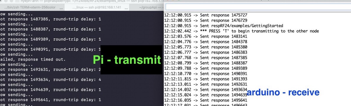
The Pi is the sender and the Arduino is the receiver.
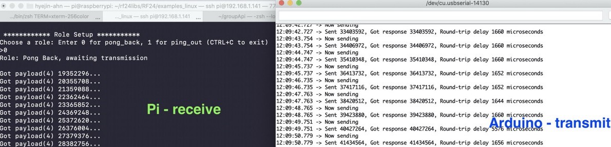
The Pi is the receiver and the Arduino is the sender.
I switched the sender and receiver on both Pi and Arduino to see if it could communicate in both directions, and it worked well.
Step 3. Using nRF24 on Node-RED
The next step was to install a package for enabling nRF24L01 on Node-RED. To do that, I followed the instructions on this site. To get it work, the previous step 1 and step 2 should be done beforehand.
I ran the following commands under $HOME/.node-red on my Raspberry Pi. After the installation, I restarted Node-RED and the new nodes for nRF24 were available under the nRF24L01 category in the palette.
npm install nrf24
npm install node-red-contrib-nrf24
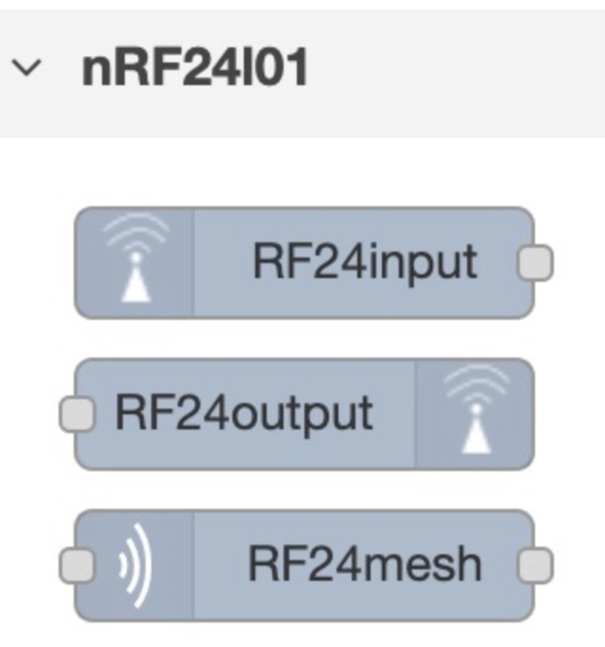
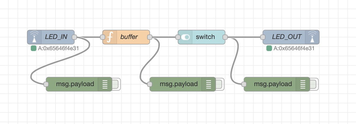
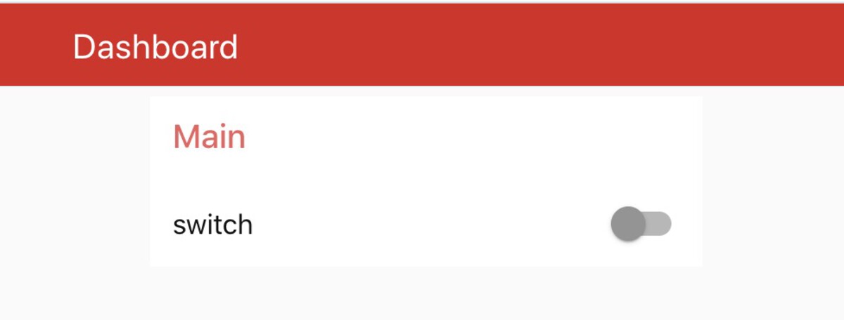
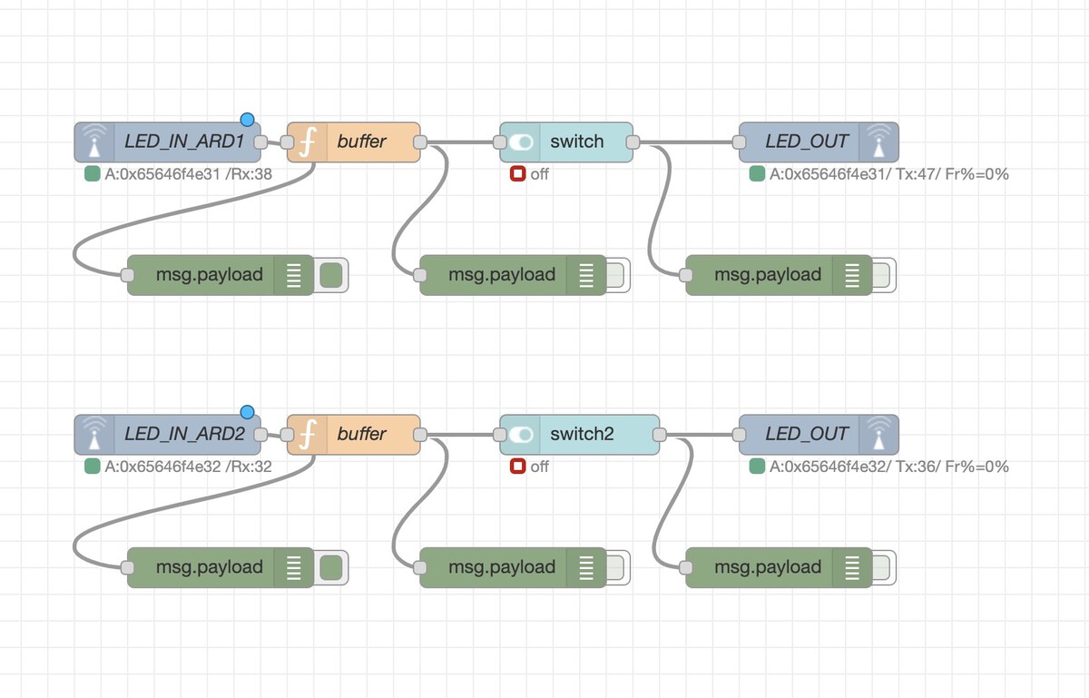
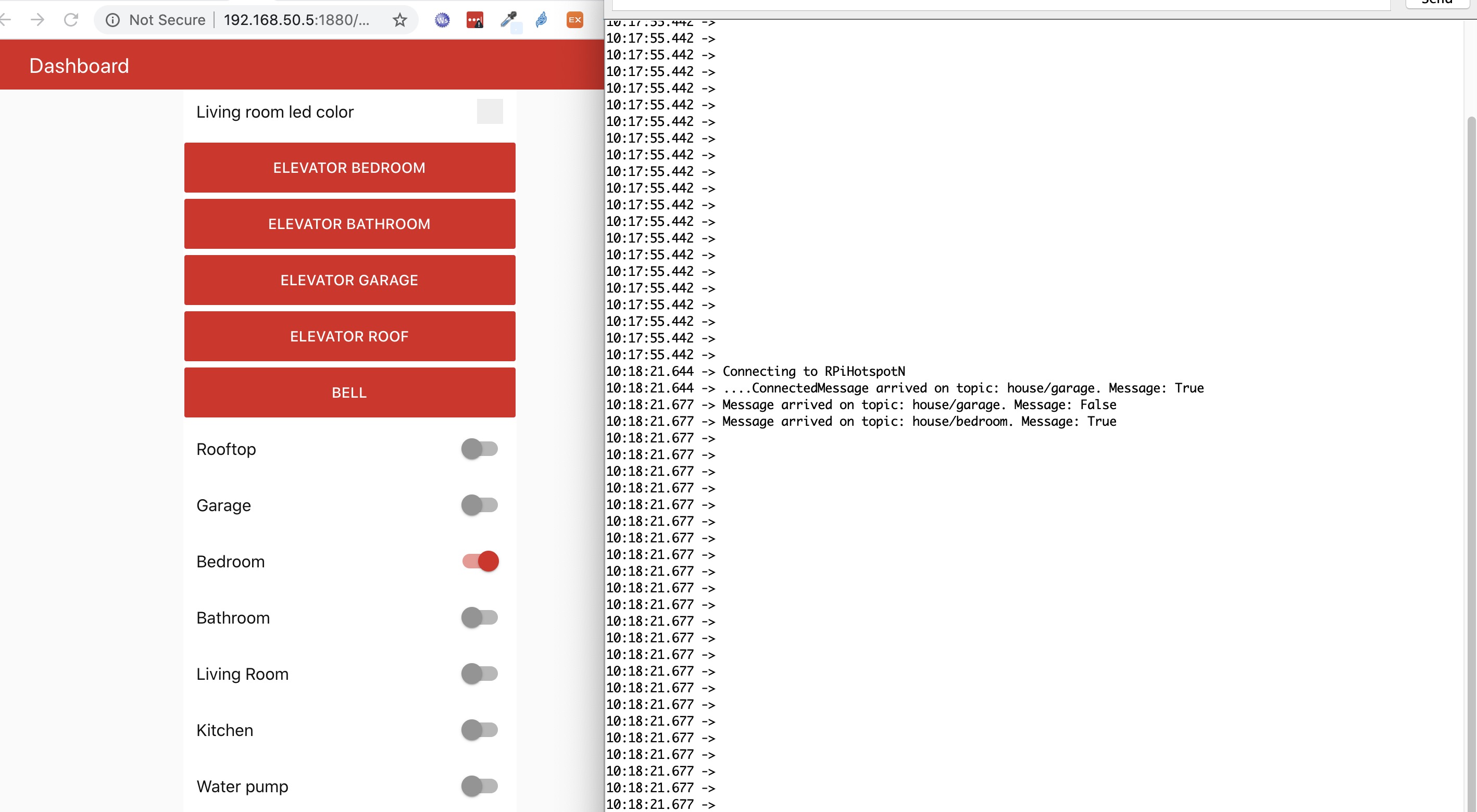
I created a flow with the nRF24 nodes. The first node (RF24input) listens to any radio signal coming to the address 0x65646f4e31, and then the payload is formatted and sent to the UI switch node. The switch on the UI will be updated depending on the value it gets from the previous node. Also, when there's change on the switch from the UI, it will send data out through the radio signal through the same address 0x65646f4e31. Basically, it receives and sends data through the address 0x65646f4e31.
JSON format for the sketch
[{"id":"c67f4eae.10e92","type":"tab","label":"Flow 3","disabled":false,"info":""},{"id":"fb3bb48e.eed918","type":"RF24output","z":"c67f4eae.10e92","name":"LED_OUT","radio":"56c0616b.c85f9","pipeaddress":"0x65646f4e31","autoack":true,"x":920,"y":160,"wires":[]},{"id":"b22a8f36.5ebc9","type":"ui_switch","z":"c67f4eae.10e92","name":"","label":"switch","tooltip":"","group":"c514a06b.47004","order":6,"width":0,"height":0,"passthru":true,"decouple":"false","topic":"","style":"","onvalue":"[1]","onvalueType":"bin","onicon":"","oncolor":"","offvalue":"[0]","offvalueType":"bin","officon":"","offcolor":"","x":730,"y":160,"wires":[["503a2618.1104e8","fb3bb48e.eed918"]]},{"id":"52b09d07.460af4","type":"RF24input","z":"c67f4eae.10e92","name":"LED_IN","topic":"nrf24","radio":"56c0616b.c85f9","outputstring":false,"pipeaddress":"0x65646f4e31","autoack":true,"x":410,"y":160,"wires":[["c3b375ac.718698","13a7b149.a0553f"]]},{"id":"503a2618.1104e8","type":"debug","z":"c67f4eae.10e92","name":"","active":false,"tosidebar":true,"console":false,"tostatus":false,"complete":"payload","targetType":"msg","x":890,"y":260,"wires":[]},{"id":"c3b375ac.718698","type":"function","z":"c67f4eae.10e92","name":"buffer","func":"msg.payload = Buffer.from([msg.payload[0]]);\nreturn msg;","outputs":1,"noerr":0,"x":570,"y":160,"wires":[["94cb886d.31fc48","b22a8f36.5ebc9"]]},{"id":"94cb886d.31fc48","type":"debug","z":"c67f4eae.10e92","name":"","active":false,"tosidebar":true,"console":false,"tostatus":false,"complete":"payload","targetType":"msg","x":690,"y":260,"wires":[]},{"id":"13a7b149.a0553f","type":"debug","z":"c67f4eae.10e92","name":"","active":false,"tosidebar":true,"console":false,"tostatus":false,"complete":"false","x":470,"y":260,"wires":[]},{"id":"56c0616b.c85f9","type":"RF24radio","z":"","name":"RF0","ce":"22","cs":"8","palevel":"3","datarate":"0","channel":"76","crclength":"2","retriesdelay":"15","retriescount":"15","payloadsize":"32"},{"id":"c514a06b.47004","type":"ui_group","z":"","name":"Main","tab":"b213d4c7.77b2a8","disp":true,"width":"6","collapse":false},{"id":"b213d4c7.77b2a8","type":"ui_tab","z":"","name":"Dashboard","icon":"dashboard"}]
The code for the Arduino (A button and LED are added to the board)
#include <SPI.h>
#include "RF24.h"

const int led = 3;
const int button = 2;

int ledState = LOW;
int ledButtonState; // the current ledReading from the input pin
int ledButtonLastState = LOW; // the previous ledReading from the input pin

unsigned long lastDebounceTime = 0; //Debouncing Time in Milliseconds
unsigned long debounceDelay = 50;


/* Hardware configuration: Set up nRF24L01 radio on SPI bus plus pins 7 & 8 */
RF24 radio(7, 8);
byte addresses[][6] = {"1Node"}; // Same as  Remote Addr on Node-RED (0x65646f4e31)


void setup() {
  Serial.begin(115200);
  radio.begin();

  radio.setPALevel(RF24_PA_LOW);

  radio.openReadingPipe(1, addresses[0]);

  // Start the radio listening for data
  radio.startListening();

  pinMode(led, OUTPUT);
  pinMode(button, INPUT_PULLUP);
  digitalWrite(led, ledState);

}

void loop() {

  ////////////////// button debouunce part start
  int ledReading = digitalRead(button);
  if (ledReading != ledButtonLastState) {
    lastDebounceTime = millis();
  }


  if ((millis() - lastDebounceTime) + debounceDelay) {
    if (ledReading != ledButtonState) {
      ledButtonState = ledReading;

      // only toggle the LED if the new button state is HIGH
      if (ledButtonState == HIGH) {
        ledState = !ledState;
        writeRadio(ledState);
      }
    }
  }

  digitalWrite(led, ledState);
  ledButtonLastState = ledReading;
  ///////////////////////// button debouunce part end

  readRadio();
}


void readRadio() {
  if ( radio.available()) {
    unsigned long value;
    // Variable for the received timestamp
    while (radio.available()) {
      radio.read( &value, sizeof(unsigned long) );
    }
    Serial.println("Recieve: ");
    Serial.println(value);


    if (value == 48) {
      ledState = LOW;
    } else if (value == 49) {
      ledState = HIGH;
    }
    digitalWrite(led, ledState);
  }

  radio.startListening(); // Now, continue listening

}


void writeRadio(bool ledButtonState) {
  delay(200);
  radio.stopListening(); // First, stop listening so we can talk.

  radio.openWritingPipe(addresses[0]);

  Serial.println("Sending");
  Serial.println(ledButtonState);
  if (!radio.write( &ledButtonState, sizeof(unsigned long) )) {
    Serial.println(F("failed"));
  }
}
The Arduino also sends and receives data through an address 0x65646f4e31 (or 1Node). In the normal state, the Arduino is listening to the radio signal coming through that address. But when the button is pressed, it stops listening, and sends the LED status data to the address. This signal with the LED status data will trigger the first node of the sketch, and the button on the board will be turned on.
I uploaded the Arduino code to the second Arduino after changing the byte addresses[][6] = {"1Node"}; to byte addresses[][6] = {"2Node"};. Then, I added the RF24 input node to the Node-RED and made it listen to the signal through the second address.
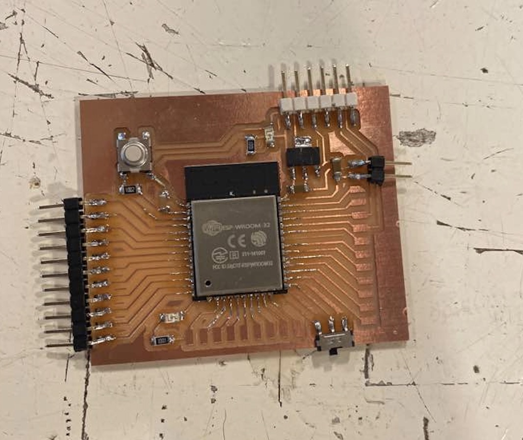
Barduino modification and MQTT protocol
For the final project, I decied to use the Barduino board. I made some modifications on it.
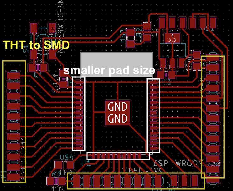
The modified barduino Kicad file can be found here.
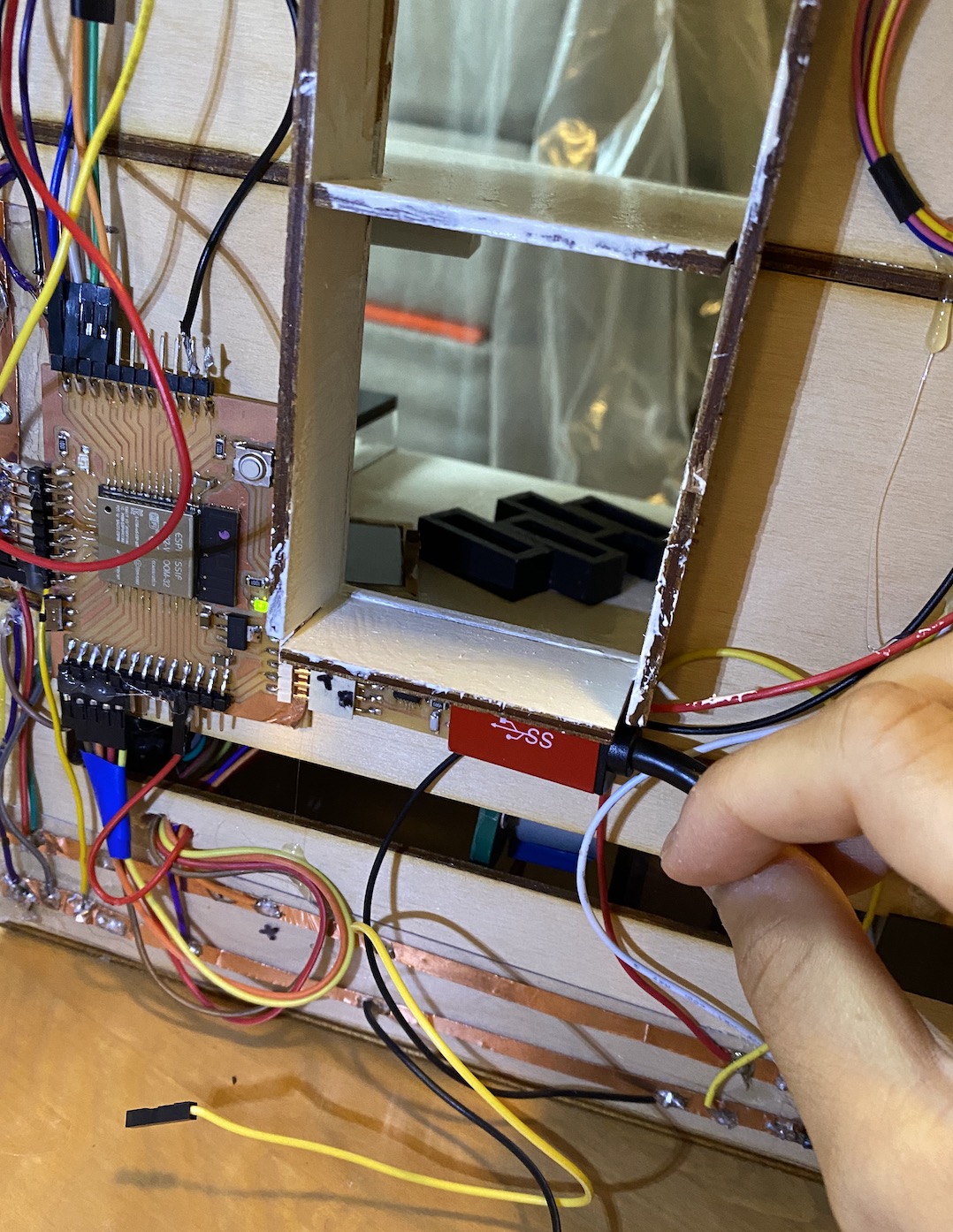
I wanted to put a camera in front of the door. That would transmits images to the LCD screen inside of the house, when someone pressed the doorbell. And the buzzer will ring when the doorbell is pressed. Also, I wanted to control an RGB LED through Node-RED and MQTT. The code can be found here.
Group assignment
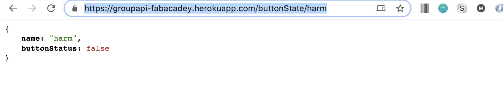
This week's group assignment is to send data between different devices. To do this, I setup the API endpoint so that other students can get the data from it. The entire documentation can be found here. For this week's group assignment, we wanted to communicate each other through a server like below.
hen a student presses a button, it will send an API request to the server. And the other side, there will be an output device fetching the data from the server and it will update the state of an output device. There are only two endpoints on the server, one for updating the boolean state, and the other one is for getting the data. I deployed on Heroku so that everyone could access to it. I created an endpoint for each student like below. The entire repo can be downloaded from here.