W08 - Embedded programming
1. Weekly Assignments ( -> what I did this week )
-
Group assignment
-
Compare the performance and development workflows for different microcontroller families
-
Document your work (in a group or individually)
( -> I tried Raspberry Pi, Scratch, LED blink. )
-
Individual assignment
-
Read the datasheet for the microcontroller you are programming
- Program the board you have made to do something, with as many different programming languages and programming environments as possible.
( -> I checked ATTiny44 datasheet, and tried LED blink/switch, C/Arduino. )
Have you?
Questions from “Fab Academy 2020 Assignments and Assessment 
( -> my answers )
-
Linked to the group assignment page ( -> yes )
-
Documented what you learned from reading a microcontroller datasheet. ( -> yes )
-
Programmed your board ( -> yes )
-
Described the programming process/es you used ( -> yes )
-
Included your source code ( -> yes )
-
Included a short ‘hero video’ of your board ( -> yes )
2. Group Assignment Link
As an example of Embedded Programming, I tried blinking LED by Scratch GPIO on Raspberry Pi ( OS ; Raspbian ).
FabLab KAMAKURA 2020 Lab site 8. Embedded Programming
3. Works, steps and some details
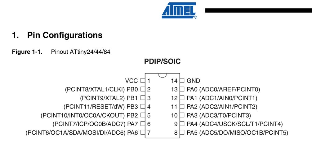
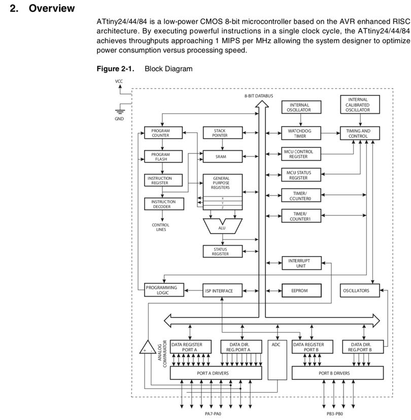
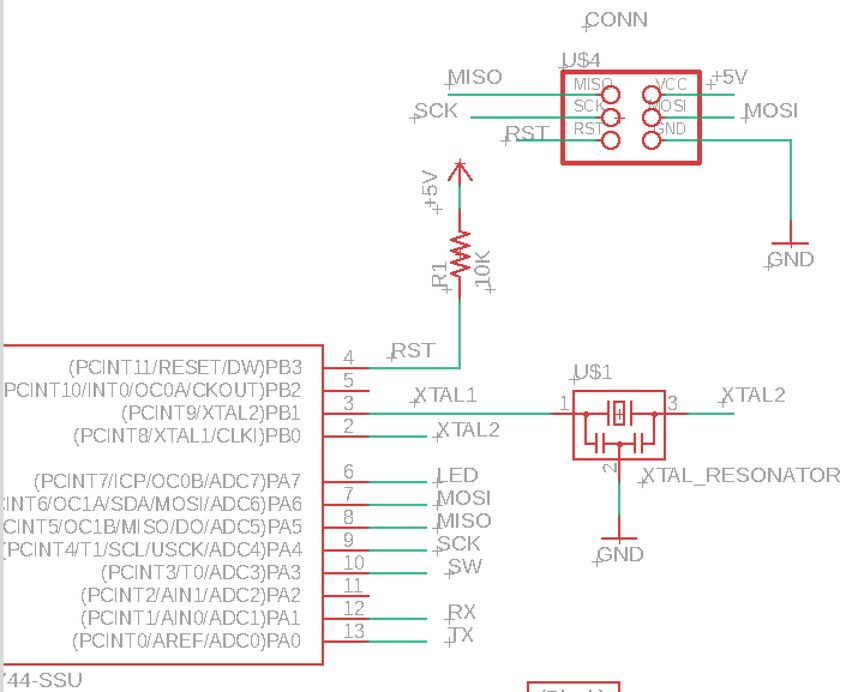
1) Reading the datasheet for the microcontroller
ATTiny44 datasheet
features
-
memory 4k
-
EEPROM
-
RAM
-
I/O Ports
 |
 |
http://fabacademy.org/2019/labs/kamakura/students/kae-nagano/assignments/week09/
2) Programing the board
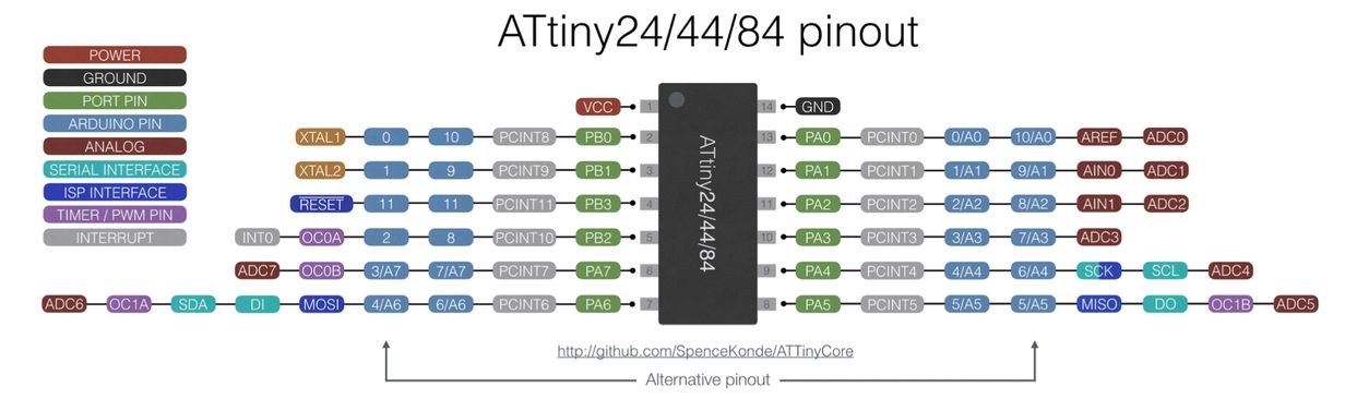
2-1) LED Button/Blink, Arduino IDE -> ATTiny44
https://www.arduino.cc/en/Tutorial/Button
change the ports
Button_FA_test.ino
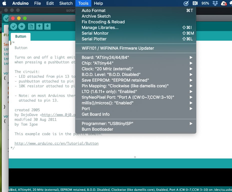
Arduino IDE tools setting
| should be 100 msec interval | |
|---|---|
 |
20 times on/off = 30 sec
0.75 sec / delay(100)
40 times on/off = 63 sec
0.79 sec / delay(100)
It seems to be 8 times faster. ( need to check the configuration )
The above testing was performed on 2020/03/21.
Then, I referred “high-low tech”, which mentions like ,,,,
“Configuring the ATtiny to run at 8 MHz”
,,,,, Then, run the “Burn Bootloader” command from the Tools menu. This configures the fuse bits of the microcontroller so it runs at 8 MHz. ,,,,,
So, I tried “Burn Bootloader” command on 2020/04/04.
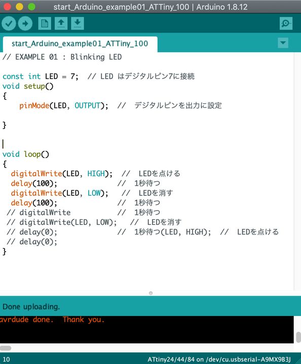
“start_Arduino_example01_ATTiny.ino”
// EXAMPLE 01 : Blinking LED

const int LED = 7;  // digital pin 7 for LED
void setup()
{
    pinMode(LED, OUTPUT);  //  set LED pin as OUTPUT

}


void loop()
{
  digitalWrite(LED, HIGH);  //  LED, ON
  delay(1000);              //  wait for 1 second
  digitalWrite(LED, LOW);   //  LED, OFF
  delay(1000);              //  wait for 1 second
 // digitalWrite(LED, HIGH);  //  LED, ON
 // delay(0);              //  wait for 1 second
 // digitalWrite(LED, LOW);   //  LED, OFF
 // delay(0);              //  wait for 1 second
}
Results were OK.
| test | clock (Arduino IDE) | delay(program) | Actual LED blink interval | result | ||
|---|---|---|---|---|---|---|
| 1 | 8 MHz (internal) | 1000 msec | 3 sec | no good | ||
| 2 | 8 MHz (internal) | 100 msec | 0.325 sec | no good | ||
| 3 | 20 MHz (external) | 100 msec | 0.78 sec | no good | ||
| 4 | 1 MHz (internal) | 1000 msec | 0.39 sec | no good | ||
| 5 | 8 MHz (internal) | [Burn Bootloader] | ||||
| 6 | 8 MHz (internal) | 1000 msec | 1.0 sec | OK | ||
| 7 | 1 MHz (internal) | [Burn Bootloader] | ||||
| 8 | 1 MHz (internal) | 1000 msec | 1.0 sec | OK |
Going back to the testing on 2020/03/21.
Button functionality.
“Button_FA_test.ino”
/*
  Button

  Turns on and off a light emitting diode(LED) connected to digital pin 7,
  when pressing a pushbutton attached to pin 3.

  The circuit:
  - LED attached from pin 7 to ground
  - pushbutton attached to pin 3 from +5V
  - 10K resistor attached to pin 3 from ground

  - Note: on most Arduinos there is already an LED on the board
    attached to pin 13.

  created 2005
  by DojoDave <http://www.0j0.org>
  modified 30 Aug 2011
  by Tom Igoe

  This example code is in the public domain.

  http://www.arduino.cc/en/Tutorial/Button
*/

// constants won't change. They're used here to set pin numbers:
const int buttonPin = 3;     // the number of the pushbutton pin
const int ledPin =  7;      // the number of the LED pin

// variables will change:
int buttonState = 0;         // variable for reading the pushbutton status

void setup() {
  // initialize the LED pin as an output:
  pinMode(ledPin, OUTPUT);
  // initialize the pushbutton pin as an input:
  pinMode(buttonPin, INPUT);
}

void loop() {
  // read the state of the pushbutton value:
  buttonState = digitalRead(buttonPin);

  // check if the pushbutton is pressed. If it is, the buttonState is HIGH:
  if (buttonState == HIGH) {
    // turn LED on:
    digitalWrite(ledPin, HIGH);
  } else {
    // turn LED off:
    digitalWrite(ledPin, LOW);
  }
}
The function was OK.
LED fade in, fade out
“start_Arduino_example04_ATTiny_100_fade.ino”
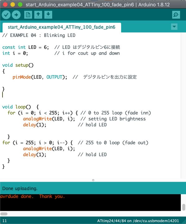
// EXAMPLE 04 : Blinking LED

const int LED = 7;  // digital pin 7 for LED
int i = 0;          // i for cout up and down

void setup()
{
    pinMode(LED, OUTPUT);  //  set LED pin as OUTPUT

}


void loop()  {
  for (i = 0; i < 255; i++) { // 0 to 255 loop (fade inn)
        analogWrite(LED, i);  // setting LED brightness
        delay(1);            // hold LED

  }
for (i = 255; i > 0; i--) {  // 255 to 0 loop (fade out)
        analogWrite(LED, i);
        delay(1);            // hold LED
  }
}
LED fade in, fade out, pin6 (MOSI)
“start_Arduino_example04_ATTiny_100_fade_pin6.ino”
 |
 |
2-2) LED Button/Blink, C-program -> ATTiny44
LED blink/switch, C-program -> ATTiny44
500 ms
“Led1_500.c”
//----------------------------------------------------------------------------------------------------
//  LED1.c       Led blink test
//----------------------------------------------------------------------------------------------------
#include <avr/io.h>
#include <util/delay.h>
#include <avr/pgmspace.h>

#define led_port PORTA
#define led_pins PINA
#define led_pin_out (1 << PA7)
#define led_direction DDRA


//----------------------------------------------------------------------------------------------------
//      main
//----------------------------------------------------------------------------------------------------
void main(void) {

   //--------  set clock divider to /1 ---------------------------

   CLKPR = (1 << CLKPCE);
   CLKPR = (0 << CLKPS3) | (0 << CLKPS2) | (0 << CLKPS1) | (0 << CLKPS0);

   //-------- initialize output pins -----------------------------

    led_port |= led_pin_out;            // set led port
    led_direction |= led_pin_out;    // set led port direction

   //-------- Loop  -----------------------------------------------

    while(1){
        led_port |= led_pin_out;            // led on
        _delay_ms(500);    //wait for 500 ms
        led_port &= (~led_pin_out);             // led off
      _delay_ms(500);    //wait for 500 ms
    }
}
“Led1_500.c.make”
PROJECT=Led1_500
SOURCES=$(PROJECT).c
MMCU=attiny44
F_CPU = 20000000

CFLAGS=-mmcu=$(MMCU) -Wall -Os -DF_CPU=$(F_CPU)

$(PROJECT).hex: $(PROJECT).out
    avr-objcopy -O ihex $(PROJECT).out $(PROJECT).c.hex;\
    avr-size --mcu=$(MMCU) --format=avr $(PROJECT).out

$(PROJECT).out: $(SOURCES)
    avr-gcc $(CFLAGS) -I./ -o $(PROJECT).out $(SOURCES)

program-bsd: $(PROJECT).hex
    avrdude -p t44 -c bsd -U flash:w:$(PROJECT).c.hex

program-dasa: $(PROJECT).hex
    avrdude -p t44 -P /dev/ttyUSB0 -c dasa -U flash:w:$(PROJECT).c.hex

program-avrisp2: $(PROJECT).hex
    avrdude -p t44 -P usb -c avrisp2 -U flash:w:$(PROJECT).c.hex

program-avrisp2-fuses: $(PROJECT).hex
    avrdude -p t44 -P usb -c avrisp2 -U lfuse:w:0x5E:m

program-usbtiny: $(PROJECT).hex
    avrdude -p t44 -P usb -c usbtiny -U flash:w:$(PROJECT).c.hex

program-usbtiny-fuses: $(PROJECT).hex
    avrdude -p t44 -P usb -c usbtiny -U lfuse:w:0x5E:m

program-dragon: $(PROJECT).hex
    avrdude -p t44 -P usb -c dragon_isp -U flash:w:$(PROJECT).c.hex

program-ice: $(PROJECT).hex
    avrdude -p t44 -P usb -c atmelice_isp -U flash:w:$(PROJECT).c.hex
make -f Led1_500.c.make
make -f Led1_500.c.make program-usbtiny
The result was OK.
4. Additional testing regarding the Clock and Low Fuse Byte setting
( a ) What kind of items were tested and clarified?
-
Reproducing the phenomena observed on 2020/03/21 ( clock seemed to be different from the setting in Arduino IDE, although the behavior with C-program was OK ), then clarifying their root causes ( item (d) below ).
-
Reviewing ATtiny44 data sheet to confirm the relation between “Clock selection”, “Clock Pre-scaler (divider) ” and “Low Fuse Byte” ( item (b) )
-
Testing the relation between the actual clock ( delay time of LED Blink ), “Low Fuse Byte” and “Burn Bootloader” command in Arduino IDE ( item ( e ) )
-
With “Clock Pre-scaler” setting in C-program, Testing similar to the above ( item ( f ) )
-
All Test results and Programs are summarized in item ( c ).
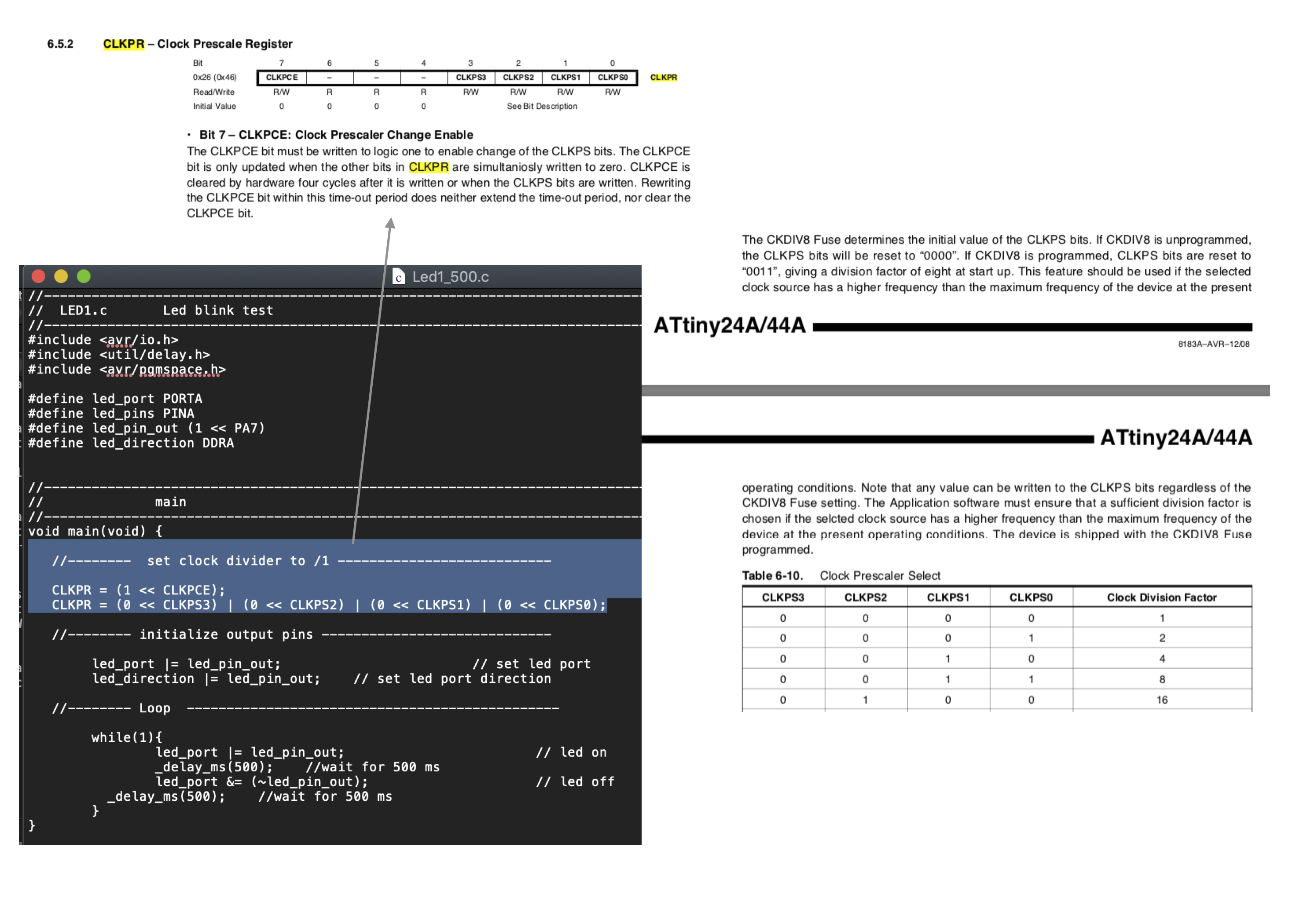
( b ) ATtiny44 data sheet review
(b-1) Relation between “Clock selection”, “Clock Pre-scaler (divider) ” and “Low Fuse Byte”
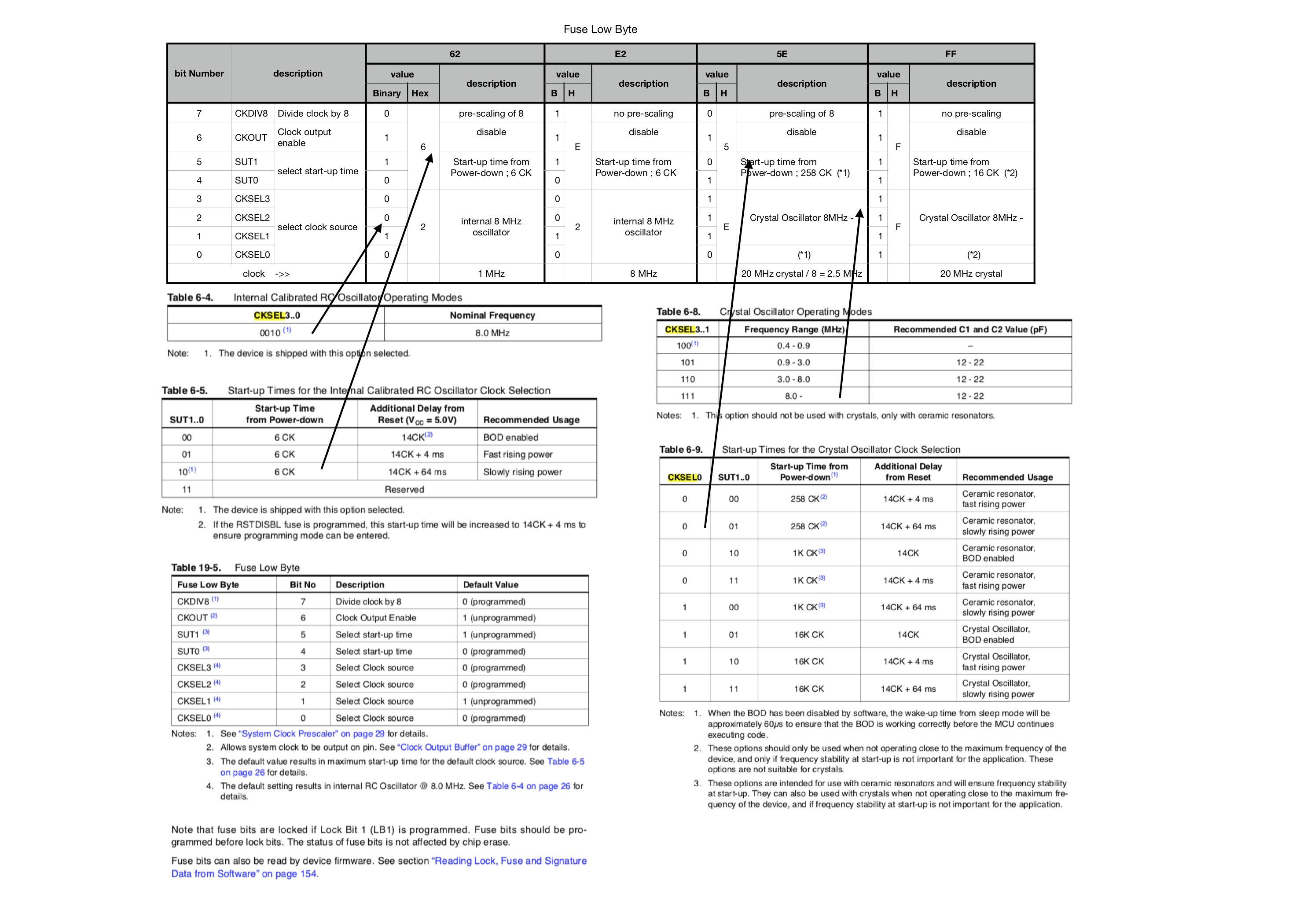
(b-2) Clock pre-scaler ( “set clock divider to /1” ) in C-program
In the C-program “Led1_500.c” ( also, hello.ftdi.44.echo.c ) includes the code below.
// set clock divider to /1
//
CLKPR = (1 << CLKPCE);
CLKPR = (0 << CLKPS3) | (0 << CLKPS2) | (0 << CLKPS1) | (0 << CLKPS0);
This sets the clock divider ( pre-scaler ) to “one”, as described in the data sheet.
( And, I found that this takes priority over the “Low Fuse Byte setting” by “.make file”, through the testing in ( item C ) below. )
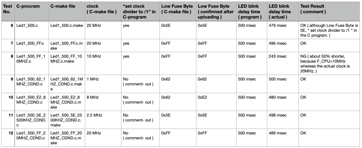
( c ) Test summary and program files
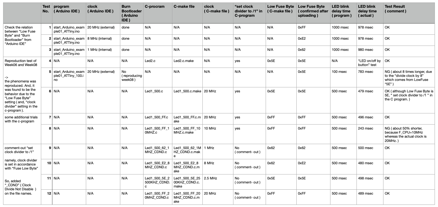
Program download ( click the file names to download )
Test No.1 , 2 , 3 start_Arduino_example01_ATTiny.ino
Test No.4 Led2.c , Led2.c.make
Test No.5 start_Arduino_example01_ATTiny_100.ino
Test No.6 Led1_500.c , Led1_500.c.make
Test No.7 Led1_500_FF.c , Led1_500_FF.c.make
Test No.8 Led1_500_FF_10MHZ.c , Led1_500_FF_10MHZ.c.make
Test No.9 Led1_500_62_1MHZ_CDND.c , Led1_500_62_1MHZ_CDND.c.make
Test No.10 Led1_500_E2_8MHZ_CDND.c , Led1_500_E2_8MHZ_CDND.c.make
Test No.11 Led1_500_5E_2500KHZ_CDND.c , Led1_500_5E_2500KHZ_CDND.c.make
Test No.12 Led1_500_FF_20MHZ_CDND.c , Led1_500_FF_20MHZ_CDND.c.make
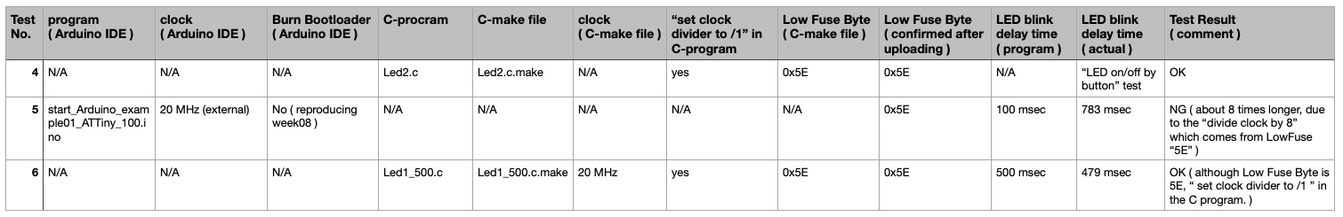
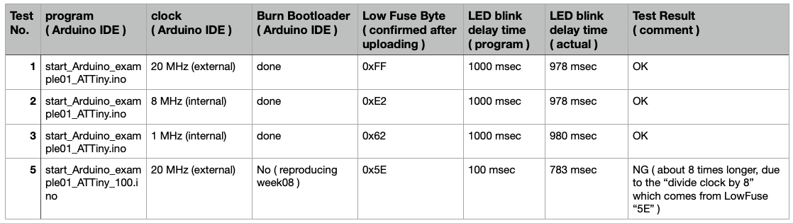
( d ) Reproduction test of Week08
-
the phenomena was reproduced. ( clock seemed to be different from the setting in Arduino IDE, although the behavior with C-program was OK )
-
And, it was found to be the behavior due to the “Low Fuse Byte” setting ( and, “clock divider” setting in the c-program ).
This sets the clock divider ( pre-scaler ) to “one”, as described in the data sheet.
( And, I found that this takes priority over the “Low Fuse Byte setting” by “.make file”, through the testing in ( item C ) below. )
( e ) Arduino IDE, “Burn Bootloader”
Check the relation between “Low Fuse Byte” and “Burn Bootloader” from “Arduino IDE”
To check the actual “Low Fuse Byte” uploaded in ATtiny44, the command below was used from “Terminal” in MacBook Pro.
avrdude -p t44 -P usb -c usbtiny -b 19200 -U lfuse:r:con:h
( f ) C-program, “set clock divider to /1”
some additional trials with the c-program
comment-out “set clock divider to /1” namely, clock divider is set in accordance with “Fuse Low Byte” So, added “_CDND” ( Clock Divide Not Disable ) on the file names.
To check the actual “Low Fuse Byte” uploaded in ATtiny44, the command below was used from “Terminal” in MacBook Pro.
avrdude -p t44 -P usb -c usbtiny -b 19200 -U lfuse:r:con:h
5. Important Learning Outcome
1) I could try several platforms and programming systems ( languages ).
2) I confirmed the relation between the actual clock ( delay time of LED Blink ), “Low Fuse Byte”, “Burn Bootloader” command in Arduino IDE , and “Clock Pre-scaler” setting in C-program as described in the Section 4.
6. Links to Files and Code ( other than Section 4 )
“start_Arduino_example01_ATTiny_100.ino” download
“start_Arduino_example01_ATTiny.ino” download
“Button_FA_test.ino” download
“start_Arduino_example04_ATTiny_100_fade.ino” download
“start_Arduino_example04_ATTiny_100_fade_pin6.ino” download
“LED1_500.c” download
“Led1_500.c.make” download
7. Appendix
embedded programing
“Fab Academy Kae Nagano, 9. Embedded programming”
“Fab Academy Jun Kawahara, 9. Embedded programming”