W14 - Networking and communications
1. Weekly Assignments ( -> what I did this week )
-
Individual assignment
-
design, build, and connect wired or wireless node(s) with network or bus addresses.
( -> I tried I2C communication by using ATtiny44 board which I made in week08, also tried ESP32 with iPhone via wifi. )
-
Group assignment
-
Send a message between two projects.
( -> In accordance with Homma-san’s instruction ( fablab Kannai), I tried MQTT (ESP32-AWS IoT) )
| test | device1 | pin | network | device2 | pin | |
|---|---|---|---|---|---|---|
| 1 | I2C | Arduino UNO (master) |
A4(SDA) A5(SCL) |
I2C | Arduino UNO R3 (slave) |
A4(SDA) A5(SCL) |
| 2 | I2C | Arduino UNO (master) |
A4(SDA) A5(SCL) |
I2C | ATtiny44 (slave) |
PA6(SDA) PA4(SCL) |
| 3 | http | Macbook Pro | none | (wifi) | Barduino (ESP32) |
(wifi) |
| 4 | Blynk | iPhone | none | (wifi) | Barduino (ESP32) |
(wifi) |
Have you?
Questions from “Fab Academy 2020 Assignments and Assessment 
( -> my answers )
- Linked to the group assignment page ( -> yes )
- Documented your project. ( -> yes )
- Documented what you have learned from implementing networking and/or communication protocols ( -> yes )
- Explained the programming process/es you used. ( -> yes )
- Outlined problems and how you fixed them ( -> yes )
- Included design files (or linked to where they are located if you are using a board you have designed and fabricated earlier) and original code. ( -> yes )
2. Group Assignment Link
MQTT (ESP32 as a pubsub client - AWS IoT as a MQTT broker) by Tatsuro Homma (fablab Kannai 2020)
I joined this MQTT testing using my Barduino board from my site.
3. Works, steps and some details
1) Test 1
| test | device1 | pin | network | device2 | pin | |
|---|---|---|---|---|---|---|
| 1 | I2C | Arduino UNO (master) |
A4(SDA) A5(SCL) |
I2C | Arduino UNO R3 (slave) |
A4(SDA) A5(SCL) |
“slave” MC sends the count up to “master” MC ( serial plotter on “master” MC is shown in the video )
“I2C-master.ino”
#include <Wire.h>

void setup()
{
    Serial.begin(9600);
    Wire.begin(); // set this MC as master
}

void loop()
{
    // request bytes from a slave device
    Wire.requestFrom(0x1E, 1);

    while(Wire.available())
    {
         //Reads a byte that was transmitted from a slave device
        byte num = Wire.read();
        Serial.println(num);
    }

    delay(500);
}
“I2C-slave.ino”
#include <Wire.h>
void setup()
{
  // set this MC as slave, address 0x1E
  Wire.begin(0x1E);
  // Register a function to be called
  // when a master requests data from this slave device.
  Wire.onRequest(send_count);
}

byte count = 0;

void loop()
{
    delay(500);
}

void send_count()
{
    Wire.write(count);
    count++;
}
2) Test 2
| test | device1 | pin | network | device2 | pin | |
|---|---|---|---|---|---|---|
| 2 | I2C | Arduino UNO (master) |
A4(SDA) A5(SCL) |
I2C | ATtiny44 (slave) |
PA6(SDA) PA4(SCL) |
codes are same as Test 1.
“slave” MC sends the count up to “master” MC ( serial plotter on “master” MC is shown in the video )
3-1) Preparation for Test 3
nodeMCU32S , LED blink test
( Because this was my first experience that I used ESP32, I tried this dev kit before Barduino. )
I installed “CP210x USB - UART” driver so that USB port is recognized by MacBook.
CP210x USB to UART Bridge VCP Drivers
CP210x USB to UART Bridge VCP Drivers (English)
Also, I added 0.1uF capacitor in between EN and GND on breadboard.
Then, I tried LED blink test. ( “Blink_ESP32.ino” link to the file is shown below)
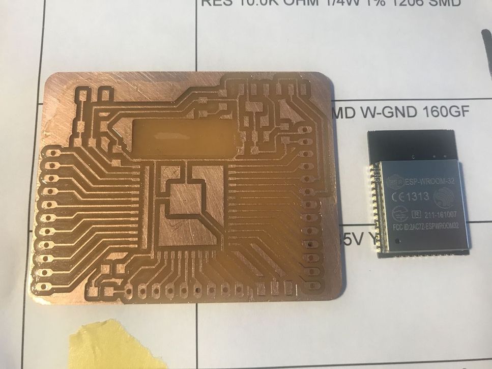
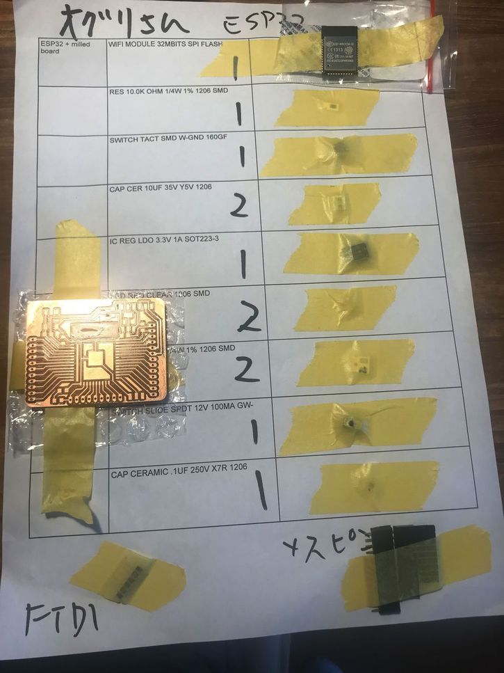
Barduino2.0 class kit, soldering and functionality check
I confirmed the functionalities according to the tutorial below.
Barduino (fablab Kamakura-site)
( Barduino 2.0 (GitLab) )
1) soldering
 |
 |
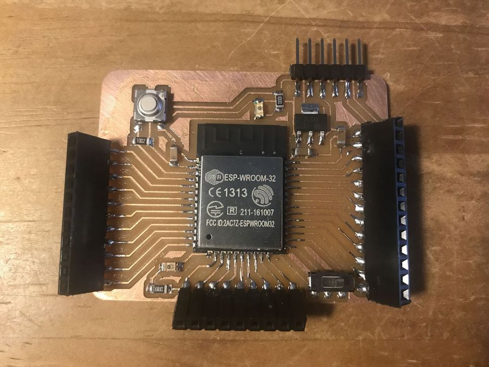 |
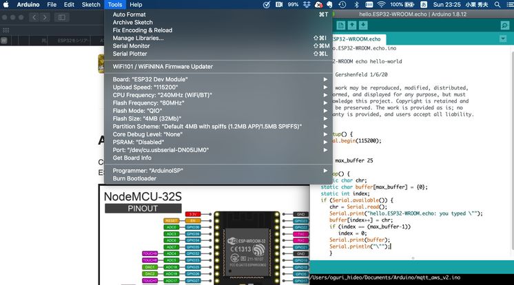
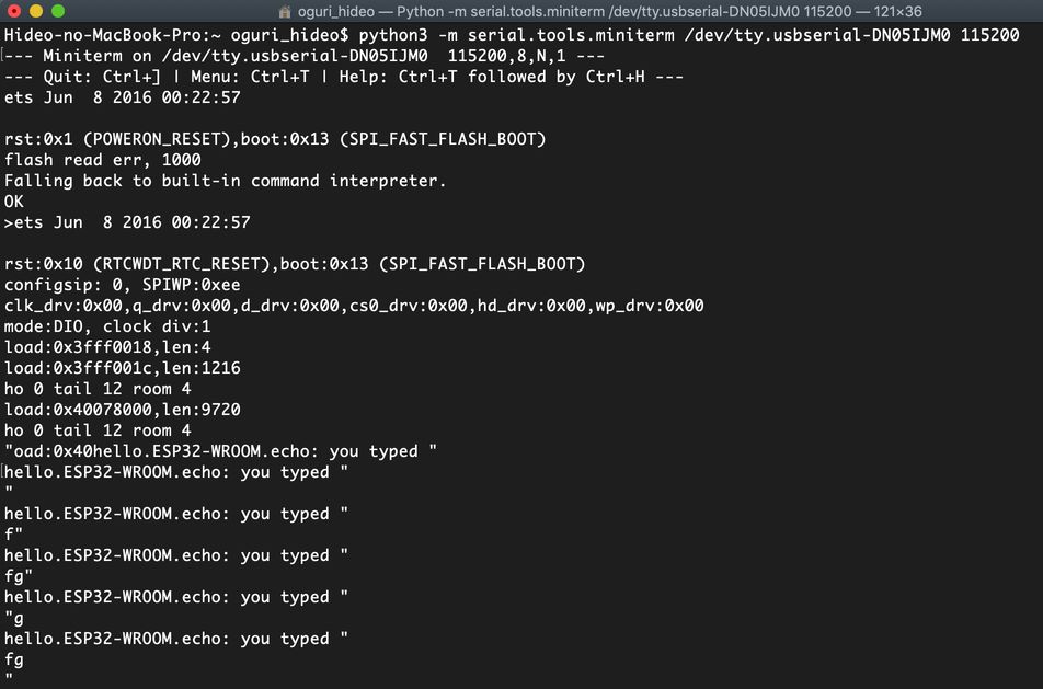
2) hello.ESP32-WROOM.echo(arduino) ( “hello.ESP32-WROOM.echo.ino” )
3) LED Blink ( “Blink_ESP32.ino” file download link is shown below)
In addition to the above, I did ,,,
(a) install “pyserial” , because I found an error message “Error: No module named ‘serial’ ” from Terminal on MacBook.
pip3 install pyserial
(b) use the external power source ( 5V regulator + (1.5V battery X 6) ) instead of Mac USB while wifi communication from ESP32, because I got a message “Brownout detector was triggered” which means “not enough power provided by the computer USB port”, etc.
ref. 8. Error: “Brownout detector was triggered”
3-2) test 3
| test | device1 | pin | network | device2 | pin | |
|---|---|---|---|---|---|---|
| 3 | http | Macbook Pro | none | (wifi) | Barduino (ESP32) |
(wifi) |
LED on ESP32 board (Barduino) blinks in accordance with “click” on the hypertext from browser.
“SimpleWiFiServer-Barduino.ino” ( file download link is shown below )
4) Test 4
| test | device1 | pin | network | device2 | pin | |
|---|---|---|---|---|---|---|
| 4 | Blynk | iPhone | none | (wifi) | Barduino (ESP32) |
(wifi) |
LED on ESP32 board (Barduino) blinks in accordance with “click” on the hypertext from browser.
I added Blynk library in Arduino IDE.
code is in the above tutorial.
“ESP32_WiFi_TBnet.ino ( file download link is shown below )
4. Important Learning Outcome
1) I2C is simple solution to connect the MCs.
2) ESP32 is powerful but it consumes power, so I need to improve the power supply for it.
5. Links to Files and Code
Test1, Test2
“I2C-master.ino” download
“I2C-slave.ino” download
preparation for Test 3
“Blink_ESP32.ino” download
“hello.ESP32-WROOM.echo.ino” download
Test 3
“SimpleWiFiServer-Barduino.ino” download
Test 4
“ESP32_WiFi_TBnet.ino” download
6. Appendix
Arduino I2C example ( Japanese )