14. Networking and communications
| This weeks design | |
|---|---|
| Slave code | ino |
| twosonar | ino |
| stepper | sch |
| stepper | pro |
| twosonar | sch |
| twosonar | pro |
| add on satchakit | sch |
| add on satchakit | pro |
| Slides Network |
Lecture on networking
There are several reasons to choose for networking in your design. I am now slowly coming to the end of the academy and i focus on the final assignment i want to make. On a personal note i have two main reasons to incorporate network in my design. 1. Easier to debug small pcb designs. 2. The amount of pins necessary. I have several input and output devices and one processor won’t have the needed pins.
The most simple way of networking is asynchronous which connect the different devices by using a cable. The data is send using rx and tx. This way of networking does not share timing since every device works with a own clock. For communication it is important that they run on the same timing. There has to be agreement on both rx and tx pin over bautrate, data bits, parivy, stop. The start is indicated with the ‘Start’ bit. RX uses falling edge of start bit to synchronize. 1st sample at 1/2 bit time interval. Subsequent samples at bit time interval, for #bits agreed betw TX & RX. (source skeatz)
This is why u have to make use of a bootloader to synchronise the differents clock.
When coding in arduino you start with serial.Begin and then the baud rate. Which is the amount of bits that is transfered over a serial line every second. A common baudrate is 9600. The different boards need to have the same speed in order to communicate.
The data that is send over a line is called package. A package is divided in four part. Start 1 bit, data 5 -9 bits, parity 1 bit and stop 1 -2 bits.
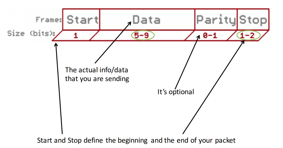 the package how data is send
Normally communications happen through uart hardware. In the microprocessors available we have often not this option and this is solved by Software.Serial in a proces called bit-banged.
In a software called logic analyzer you can see the actual data in how it is send in binary code. It use the package to send the information. Starting with Start, the the letter H of hellow world. A parity and then stop. It gave a nice insight of how binairy code works.
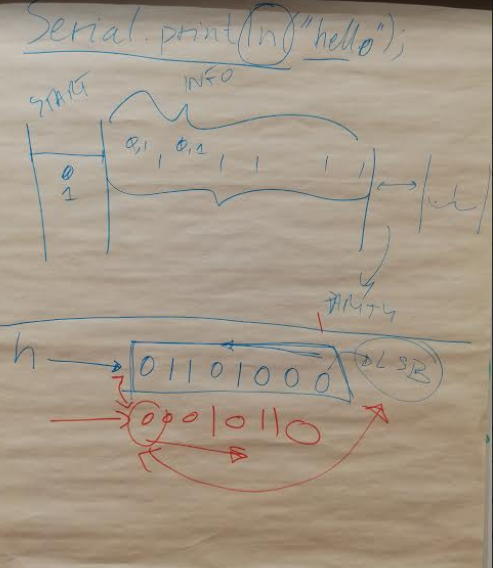 Sketch by temporary instructor Emma showing the package in binary code
The code is send in reverse starting with LSB (Least sygnificant bit) Acynchronous serial bus.
The Bridge (main device) can have separate Vcc then nodes but has to have a common ground when connected. The bridge is the only board that can send data and read data to the different nodes. The nodes cant read own data.
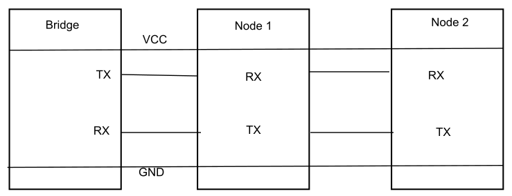 Overview asynchronous Serial Bus
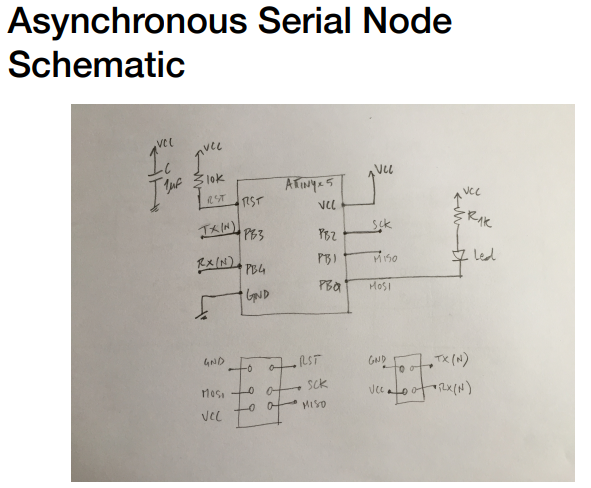
To use this wired network you need a four pin header using vcc,gnd, rx and tx. In the image below you see a schematic of a board using asynchronous network. What noticed is that between Vcc andf Gnd you Always use a capicitor to deal with voltage drops to ensure there will be a steady line of power. The RST is Always connected with a 10 K resistor. This ensures it stays in a solid 5 volt condition. When voltage low reset will happen. This is applied to all electronic boards. A nice reminder.
 Overview
- SPI
Spi Network difference from asynchronous in the way it send data and the clock. Where the devices are called bridge and nodes in spi they are called Master and slave (mosi, miso). In my opinion a very unnecessary outdated offensive word to describe the different boards. I noticed in electronics they are racist and sexist to describe boards and components. Anyhow… Drifting off… Spi is nevertheless a more efficient way of transmitting data. The use of the clock assures all slaves run on the time set by the master. Sound dubious right? The problem with spi is the amount of devices(slaves) you can connect to the master. For every extra board you need addition pins to connect them.
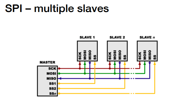 Overview of network of SPI
- I2C
This is a more efficient way of networking then the previous examples. Where the operate using separate wire for transmitting and receiving (rx, tx, Miso, Mosi), I2C uses one cable for transmitting data (SDA) to both directions and a clock (SCL) to pass the frequency of the master. Less cables needed for mor efficient networking. Another good things it is able to communicate with up to 1008 devices with this method. I got this information from the slide of our instructor Emma. This article shows the maximum connection of 1008 devices by the use of two wires.
 SDA and scl transmit data and frequency
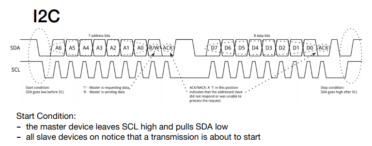
The starting condition is with high volt and the moment the voltage drop it starts communicate. Then the package of data will be send. The first frame is for address (which device is the code mend for) Afterwards its starts sending the data. When finished the voltage should be high again. * Voltage scl and Sda High * Start condition: Drop voltage * 7 bits for address * 1 bit Read/Write * 1 bit –> Acknowledgment
- 8 bits Data
- 1 bit acknowledgment
- Stop condition Scl high voltage and sda high voltage
in a nice scematic they explained that for i2c you NEED to use pull up resistors to have a high voltage starting point. Another key thing to do when setting the conditions that you sett the frequency of the master on 1 MHZ and the slaves on 8 MHZ. This is important otherwise the serial software library wont accpt a i2c connection. source
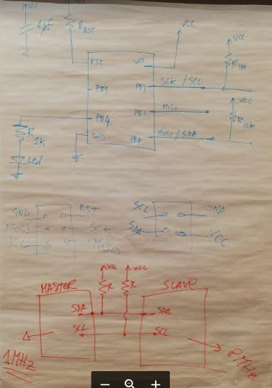
Scematic master using i2c
When using longer cables to connect to devices make sure you use the Pull up resistors in every board in able to function.
When programming code to the Master and slaves you need to use the Attiny librar. For master use tinyWireM and for slaves TinyWireS. When using Atmega 328 Proccessor you need to use again a different library. To define the adress of the device the i2c network use 0X01, 0X02 addresses.
- Wireless
Since electronics is complicated enough as it is i decided not to incorparate wireless devices in my final assigment. There are seeral different devices to enable you to have wireless connection. Like bluetooth, radio and wifi. I will not explain them. If you are interested of learning more you can see the lecture of neil. In the pdf added with the files of this week you can see the slides of the local lecture where also the coding of the boards is explained.
Groups assignment
For the groups assignment we had to connect our devices and work with addresses to control them. We just used simple blinking led to show that the different micro controllers communicate with eachother. We used a serial bus to archieve communications.
Here was the code of one of the nodes.
#include <SoftwareSerial.h>
#define rxPin 1
#define txPin 0


SoftwareSerial serial(rxPin, txPin);
int bridge_communication = 0;
int ledPin = 7;
int node_id = 1;


void setup() {
  // put your setup code here, to run once:
  pinMode(rxPin, INPUT);
  pinMode(txPin, OUTPUT);
  pinMode(ledPin, OUTPUT);
  digitalWrite(ledPin, LOW);
  serial.begin(9600);

}

void loop() {


  if (serial.available() > 0 ) {
    // read the incoming byte:
    bridge_communication = serial.read();

    if (bridge_communication == '1') {
      digitalWrite(ledPin, HIGH);
      delay (500);
      digitalWrite(ledPin, LOW);
      delay (500);
      digitalWrite(ledPin, HIGH);
      delay (500);
      digitalWrite(ledPin, LOW);
      delay (500);
      digitalWrite(ledPin, HIGH);
      delay (1000);
    }
    else {
      bridge_communication = 0;
      digitalWrite(ledPin, LOW);
      delay (1000);
    }
  }
}
The master code
*/
#include <SoftwareSerial.h>
const int RX = 1;
const int TX = 0;

SoftwareSerial mySerial(RX, TX);

int received = 0;

const int LED_PIN = 7;
void setup() {
  pinMode(RX, INPUT);
  pinMode(TX, OUTPUT);
  mySerial.begin(9600);

  // declare the LED pin as an OUTPUT:
  pinMode(LED_PIN, OUTPUT);
}

void loop() {
  //reset all lights
  digitalWrite(LED_PIN, HIGH);
  delay(50);
  digitalWrite(LED_PIN, LOW);
  mySerial.print(0);
  delay(2000);

  //turn on light 1
  digitalWrite(LED_PIN, HIGH);
  delay(50);
  digitalWrite(LED_PIN, LOW);
  mySerial.print(1);
  delay(2000);

  //turn on light 2
  digitalWrite(LED_PIN, HIGH);
  delay(50);
  digitalWrite(LED_PIN, LOW);
  mySerial.print(2);
  delay(2000);
}
Working i2c connection
i2c from Rutger Oomkes on Vimeo.
Satcha kit to be prepared
For this week i realized i need to connect multiple board and make them work together. With this in mind and my final assignment i decided to make a satcha kit inspired on the specialized board made by my fellow student Anne Vlaanderen. This board serve the same purpose as a arduino uno board and can come in handy when when experimenting or connecting multiple devices.
For the board design i looked at Anne output week to make my own board. With her permission of course. Anne Vlaanderen
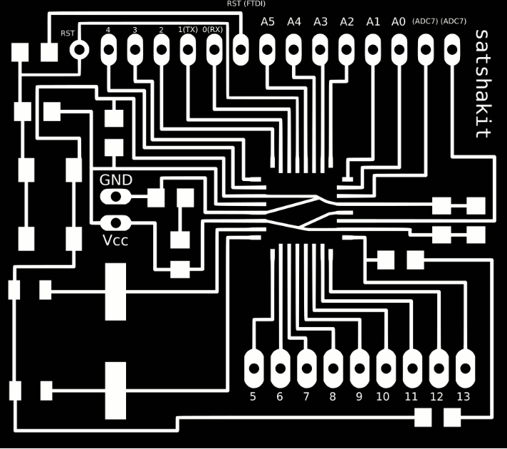
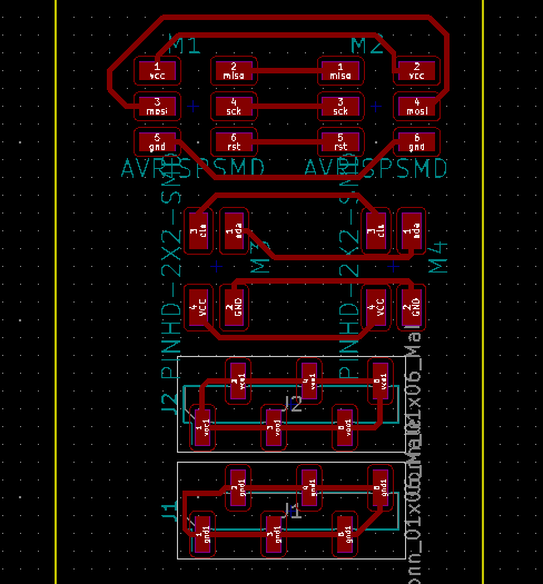
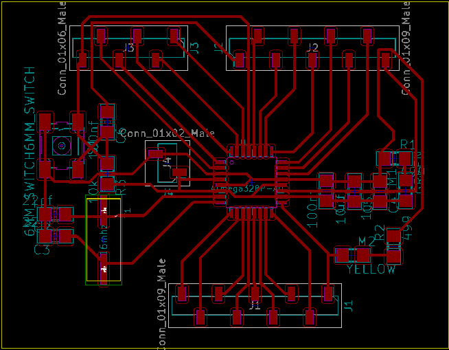 Traces of the board design
For performing the bootloader i used the instructions of the fabacademy archives. archive
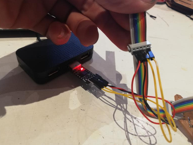
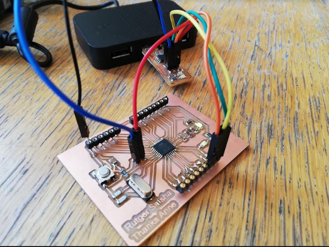 Board connected to usbtiny
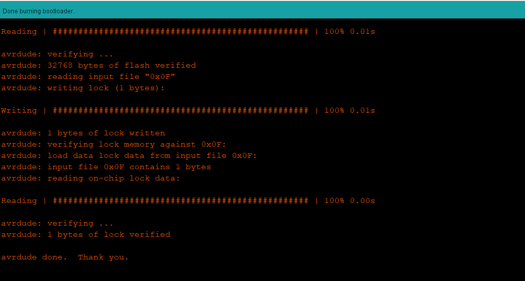 Succesfull boatloader
This device works with a more powerful micro controller with more pins you can use. In the picture below a overview of the pins of the amega328.
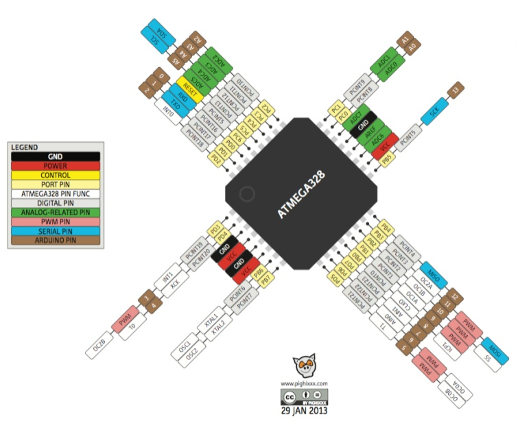 Pins of the Atmega 328P
 Overview functions different pins Satchakit
Addition to Satcha kit
I made the board last week in preparation of this week. The board is nice and practical to have but it does not have a clear ISP input or i2c connectors. I thought it would be nice to make a simple board with those entry to be able to connect the device when doing networking.
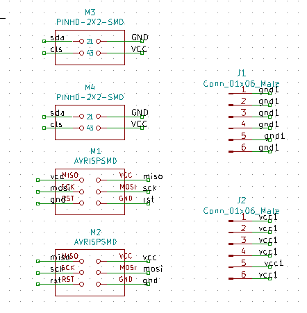 Schemtatic of the extension
I decided to also add more GND connectors and vcc connectors. Not sure if if it works. To be able to connect the two isp header i made one isp in reverse so that the trace would align better. I assume this is no issue since you have to connect loose wires. But important to keep in mind when connecting with isp. The i2c was not hard to connect the traces and are identical.
 Extension board
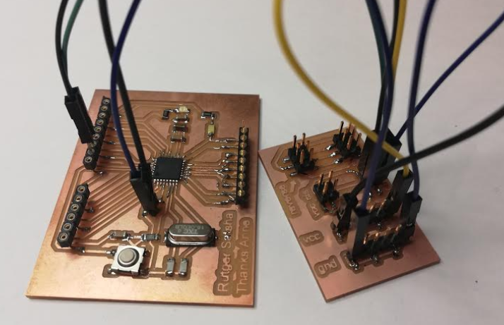 The satchakit and add on board
Designing a board
I want to control the different parts i need for my final assignment with the use of i2c. I looked at my old boards to see how i could incorparate them. Since i need to show a network between different boards i was hoping to use the sonar and led i made during output week. Somehow i was not recieving data anymore on my serial monitor.
I did some debugging. I noticed when i tried to upload the code it ony wwent trough when pressing the spi header. And the led seem to go on and off unexpected. Checked the spi cable to ensure there was no issue there and used the voltmeter to check my board. I think during transport the board was slightly damaged. Could not find a straight answer but noticed the spi header on my board was not 100% straight on there. I tried to redo the job. With the hot air gun i removed the spi header and removed the solder on the board. When doing this it went wrong and i destroyed the foot print.. I tried to fix it with solder but unsuccesfull. I ruined the board..
 The copper of the spi footprint ruined
On the bright side. It did not had a i2C connector. Now i was forced to create a new board. I kept my final assignment in mind and developed a board with two sonar to measure distance. I used my design i made for the input week and made some alterations to fit two sonar on the board. Also i added a 2 x2 header of the device to be able use use i2c network.
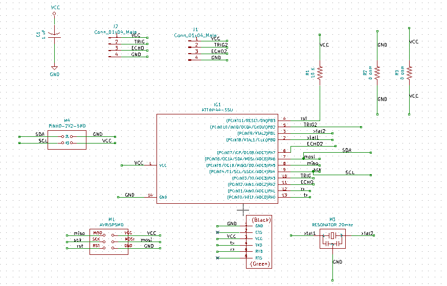 Schematics for new board with two sonar entries
This time i wanted the sonar not soldered to the board but to connect it with wires. This way i have more flexibility in placing the sonar for my final assignment. I first planned to use male connectors on my board.Ater advice of temporary teacher Emma i used female headers instead. The reason is that this type of sonar does not always react well on long wires. If this influence the measurement i still can place them straight on the board.
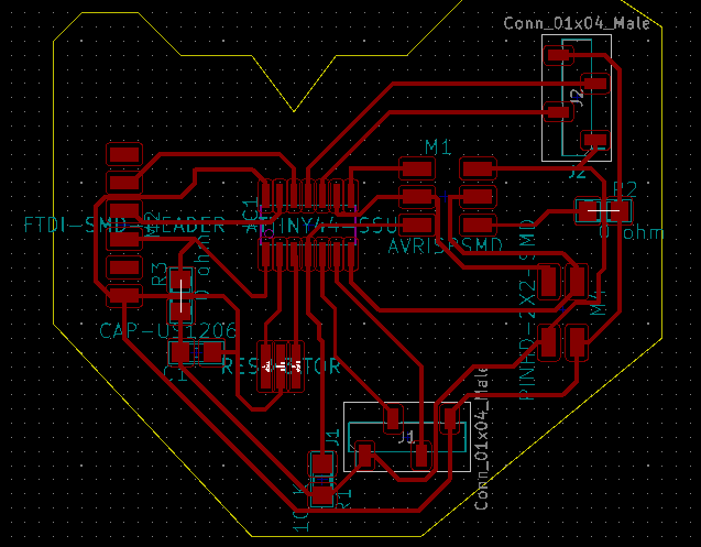 traces of board with the help of two 0 ohm resistors
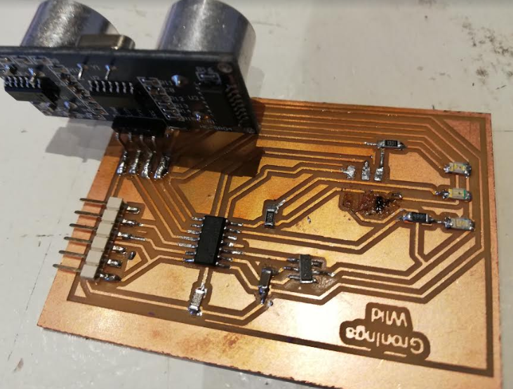
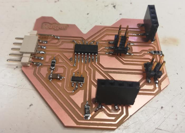 All components soldered including i2c connector
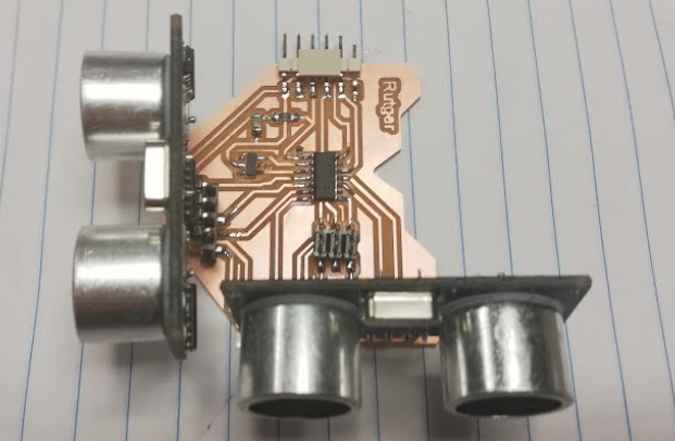 two sonar plugged in straight in board
I used Avrdude to see if it would recognize my board. A few times it recieved a error. Then i double checked the ISP cable and i had placed it wrong. When cable was set right it recognized my board.
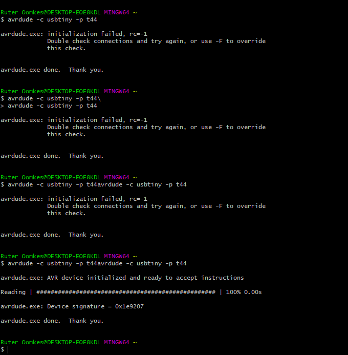 After few errors it recognized the board
in arduino IDE i was also able to do the bootloader on 20 mhz.
Successful bootloader
used my previous code and copied the code to make my second sonar. Adjusted the pins and it worked!
#include <SoftwareSerial.h> // import another program, a library, to communicate
#define rxpin 1
#define txpin 0

SoftwareSerial serial(rxpin,txpin);

int rxPin = 1; // this is simular to the int = setting, however this is linked to the library
int txPin = 0;
int trig = 3;
int echo = 2;
int trig1 = 2;
int echo1 = 7;
long lecture_echo;
long cm;
void setup()
{
  pinMode(trig, OUTPUT);
  digitalWrite(trig, LOW);
  pinMode(echo, INPUT);
  serial.begin(9600);
}
void loop()
{
  digitalWrite(trig, HIGH);
  delayMicroseconds(10);
  digitalWrite(trig, LOW);
  lecture_echo = pulseIn(echo, HIGH);
  cm = lecture_echo / 58;

  serial.print ("sonar 1 in cm: ");
  serial.println(cm);
  delay(1000);

  digitalWrite(trig1, HIGH);
  delayMicroseconds(10);
  digitalWrite(trig1, LOW);
  lecture_echo = pulseIn(echo1, HIGH);
  cm = lecture_echo / 58;

  serial.print ("sonar 2 in cm: ");
  serial.println(cm);
  delay(1000);
}
Data from both sonar is coming in using this code.
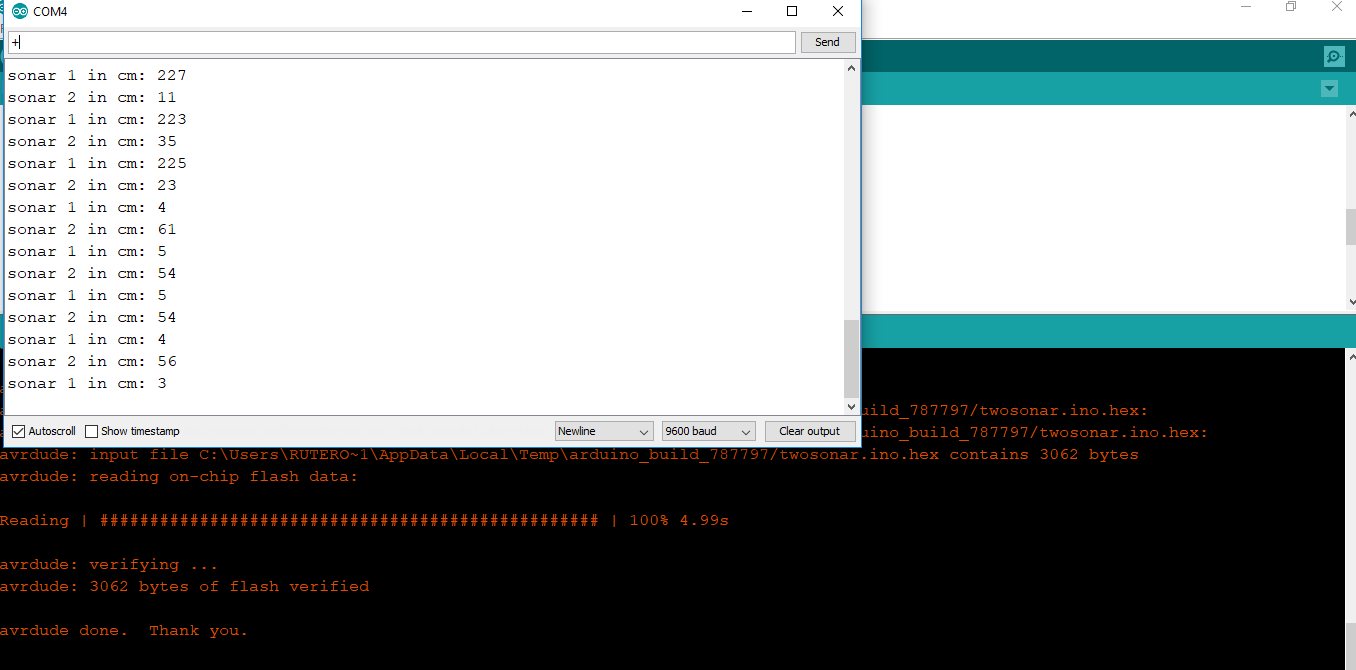 * measurement 2 sonar coming in serial monitor
Using Serial For communications
For this assignment i make use of my sonar to check the distance and depending on the distance it sends a message to the node. Unfortunately some boards malfuntion during the way and i had only access to one extra board to send the information to. The code for serial communications is pretty forward. I will explain the code of the bridge to send instructions to the nodes.
- The Bridge code
#include <SoftwareSerial.h> // import another program, a library, to communicate
#define rxPin 0 //omdraaien van nummers. De rxpin van boss moet aangesloten zijn op tx en andersom
#define txPin 1
Like all my assignments so far i make use of the softwareSerial library to communicate. The asynchronous Serial Bus communication uses the TX and RX pin to communicate from the brigde to the nodes. Here i define the pins.
SoftwareSerial serial(rxPin,txPin);

int trig = 3;
int echo = 2;
int trig1 = 8;
int echo1 = 7;
long lecture_echo;
long cm;
int timeout = 1000;
The board i use is for two sonars. Since i have issues with one sonar i decided to use one sonar for this assignment. I use the software serial for the communication with the tx and rx.
void setup()
{
//  pinMode(trig, OUTPUT);
 // digitalWrite(trig, LOW);
 // pinMode(echo, INPUT);

  pinMode(rxPin, INPUT);
  pinMode(txPin, OUTPUT);

  pinMode(trig1, OUTPUT);
  digitalWrite(trig1, LOW);
  pinMode(echo1, INPUT);

  serial.begin(9600);
}
Here i define the tx as a output and rx as a input. This enables me to communicate with the node 1. For communication it is important that the baudrate of both devices is set the same. In this case 9600.
void loop()
{
// digitalWrite(trig, HIGH);
// delayMicroseconds(10);
// digitalWrite(trig, LOW);
// lecture_echo = pulseIn(echo, HIGH,  timeout*1000);
// cm = lecture_echo / 58;

 // if (cm >= 400 || cm <= 0){
 //   serial.println("Out of range");
 // }
 // else {
 //   serial.print(cm);
 //   serial.println(" cm");

 // }
First part of the code i don’t use as placed as a message. This enable me later to change the same code to make use of two sonar again.
digitalWrite(trig1, HIGH);
delayMicroseconds(10);
digitalWrite(trig1, LOW);
lecture_echo = pulseIn(echo1, HIGH, timeout*1000); //timeout in micro seconden
cm = lecture_echo / 58;

  if (cm >= 0 && cm <= 10){
 //   serial.println("Out of range");
   serial.print(1);
  delay(3000);
  }
 // else {
//serial.print(0);
//serial.println(" cm");

 // delay(3000);
 // }

  delay(timeout);
}
Here i set the conditions for when to transmit the command to node 2. in this command: if (cm >= 0 && cm <= 10){ i decide when the distance is between 0 and 10 the serial print have to transmit 1. Otherwise it does not send information to the monitor. This is all i have to set on the bridge. Now have a look at the node.
- Node 1
The board i borrowed from my fellow student Micky and i used the code to see if i was able to get communication.
#include <SoftwareSerial.h>
#define rxPin 1
#define txPin 0
# define node_id '1'

SoftwareSerial serial(rxPin, txPin);
int bridge_communication = 0;
int ledPin = 7;
In the first part i define this board as node 1. When the board recieved the number 1 it knows it addres this board. The bridge standard is set as 0. When it addres the node 1 it should transmit 1.
void setup() {
  // put your setup code here, to run once:
  pinMode(rxPin, INPUT);
  pinMode(txPin, OUTPUT);
  pinMode(ledPin, OUTPUT);
  digitalWrite(ledPin, LOW);
  serial.begin(9600);

}
Also here the rx is set as input and tx is set as a output for communication. The serial begin is set the same baut rate as the bridge.
void loop() {
  if (serial.available() > 0 ) {
    // read the incoming byte:
    bridge_communication = serial.read();

    if (bridge_communication == node_id) {
      digitalWrite(ledPin, HIGH);
      delay (500);
      digitalWrite(ledPin, LOW);
      delay (500);
      digitalWrite(ledPin, HIGH);
      delay (500);
      digitalWrite(ledPin, LOW);
      delay (500);
      digitalWrite(ledPin, HIGH);
      delay (1000);
    }
    else {
      bridge_communication = 0;
      digitalWrite(ledPin, LOW);
      delay (1000);
    }
  }
}
The if (serial.available() > 0 ) is used for when there is information coming over the serial port in bytes, then the communication is set to the data coming in. When the data by the serial port is equal to the node id. In this case 1 since we set the node as 1. The led will blink twice. When the communication is set to 0 the led goes off. I haven’t defined the 0 in the bridge so the only input was 1. Resulting that the light stayed on after the action.
The tricky part was connecting the boards to each other and to the laptop it self. I had to improvise with the cables to make this work.
 improvise with connecting the wire
serial from Rutger Oomkes on Vimeo.
Here a video of the serial bus communication between the bridge and the node 1. I had to improvise with the cables to get it working. Everytime when i held my hand close to the sonar it transmit the number one to the seralport and the led on node 1 starts blinking.
In this case i worked with one node. You can use multiple nodes. In this case it is wise to address each node with a symbol so the node recognized when is called. source
What i learned and what went wrong.
First thing i learned this week is that electronics are fragile. The need some proper protection when transporting it. I was frustrating to fix and make new hardware before i could start doing the networking. I did learn more about electronic design and practise my soldering skills. I was a bit terrified of starting with networking. It sound complicated and it can be complicated. The serial bus communication was for me a good start in learning networking. And this can be done fairly easy compared to other methods. It felt rewarding when finally succeeded in establish a communication.