11. Input devices
| This weeks design | |
|---|---|
| sonar | ino |
| sonar.kicad_pcb | pcb |
| sonar schematic | sch |
| Sonar design | svg |
Groups assigment
For this weeks groups assignment we need to probe a input device with the oscilloscope. We used as a input device a sonar to measure distance. The device was already made with the use of a arduino, sonar hc-sr04 and a breadboard.
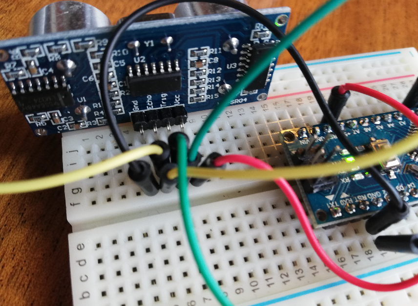 The sonar we tested
It is a bit daunting at first to start working with the oscilloscope. Not knowing well how to start and the amount of buttons available on the device. I found a manual online for the 1000 series which the buttons correspond with the device we have available at the fablab Amsterdam. Manual
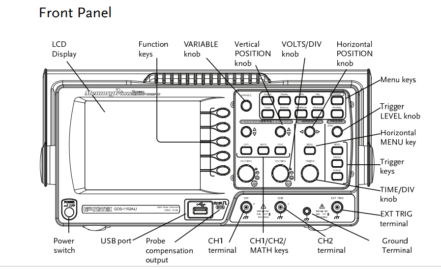 Overview of the oscilloscope
In week 7 the osciloscope is briefly explained and i explain the four sections of the device.
1. Vertical section: This section control the Amplitude of the displayed signal.
-
Horizontal section: This section controls the time base of the sweep (Wave).
-
Trigger section: Here you decide the start of the sweep. The trigger can be set to restart after each sweep or at a given event.
-
The display: Here you can set the reference lines on the horizontal and vertical axis. Further you can set the focus, intensity and the beam finder
With the group we watched a useful tutorial in how to use this machine. Youtube tutorial
We followed the instructions step by step to be able to see the electrical signal waves of the sonar we use as input.
- First we place the probe which has a ground clip in the channel 1 port. We made sure channel 1 is the only channel. By pressing channel one you can see the input settings.
- With the function button we select DC coupling to be able see see all parts of the signal. For the probe we select 10 x. Source is channel 1. The type you select on edge. And slope you set on up edge.
- On the right side you select the trigger menu button.
- As a test you connect the probe to the 1 kHh on the left of channel 1 port. The ground clip you connect to the ground as shown in image.
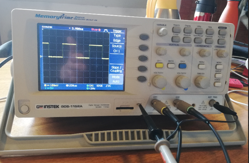 oscillator input from the sonar
- Now you receive a input on the screen showing electrical waves. With the horizontal en vertical knobs you can adjust the screen to see the waveform
- With the smaller knob on top of channel 1 you can adjust the vertical axis of the waveform. This also will move the 0 volt location.
- With the knob in the trigger section you can raise the bar to the middle of the waveform. This way it starts measuring when the wave goes up. the wave appears static on the screen.
- Make sure the wave have straight lines and edges
- Ready to start measuring
First we have to connect the probe to the device. Always connect the ground clip first and then the probe to the part you want to measure. When connected adjust the horizontal knob to adjust the time to see a waveform. Use the measure button to see data from the waveform. There is a way to manual measure waveform by pressing the cursor button and top display button. You can measure voltage or time (by selecting the button in the display menu). A line appears in the screen. First you able to move 1 line by pressing on the a button. To adjust the other line simple pres the b button n the display menu.
It is also possible to have a single sweep when your are dealing with a one time signal. Then it start measuring when the slope goes up. Set the trigger knob to the correct height. Then press signal button. This way it starts measuring the moment the is a up slope wave. This you can set accordantly. It is possible to measure a downslope when needed.
When connecting a second probe you able to measure two wavefront of different signals. For this device we want to measure the trigger and the echo of the sonar. Connect both clips to the ground and the probe to the pins. We used channel 1 for the trigger and channel 2 for the echo. We had to adjust manually to be able to see both waveforms.
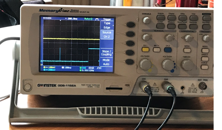 Recieving data from trigger and echo
We succeeded in receiving a input using a probe on the oscillator. Sill have to get acquainted with the device and the visual data. Hope to understand more in the coming weeks about using the device in a proper way to analyze the data.
input
This week was input week. Designing a board and program it in a way you recieve input from the board. You could choose between the different sensors available. I decided to go for the sonar sensor to measure distance. I have in mind a lamp design that change colors depending on the distance. This week i focus on getting a input on my device. Still not very comfortable with electronics so i search online for excisting board and which components they used to make it work. My instructor have used a sonar in the previous year and i used his sketches as a reverence for designing my board.
HC-SR04 Ultrasonic sensor
The sonar transmits soundwaves to determine the distance to a object. It uses a trigger to send the soundwaves and when it reach the object a echo coming back to the device. The trigger send 8 pulses to determine the distance. This result in a echo from the object.
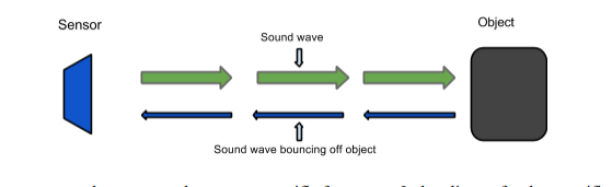 Transmit a soundwave to determine the distance
Since sonar works with sound you can calculate the distance by dividing the data with 58. Sound travels 343 meters per second. To travel 1 cm it needs 29.155 microsecond. The time the sonar needs to send and come back you can divide by 29. Since it travels the distance twice you divide the result by two. A easier method in coding is diving the data by 58. source
Designing the board
In the previous weeks i started to get acquainted with kicad. A open source pcb design tool where you can design and make a electronic circuit. I opened a new file and started looking for the components in the fab library which i added in the electronic design week.
I used the following components:
- a 10 K resistor
- ATtiny44A
- 20 mhz resonator: External clock with more accuracy
- Capacitor 1uF
- hcsr04: Arduino based sonar device
- avrispsmd 3X2 header
- Ftdi header
The sonar i could not find in the fab library so i searched online to download the schematic and footprint for this component. I downloaded the zip file and add it to the library.Footpint file
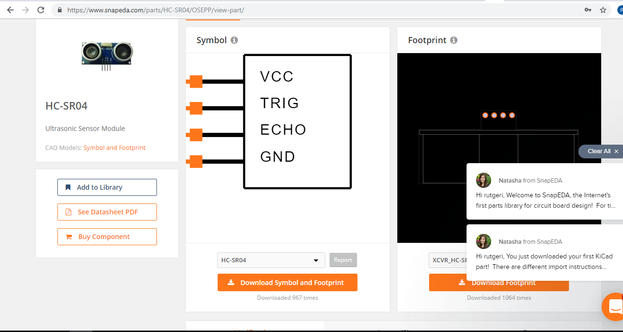 Downloading component for library
Designing the board
In the eeschema menu i placed all components and used the wire tool to connect the different pins. By naming the wires you connect the parts to each other. Wires with the same name tag the program recognize as being a connected line. I added the component VCC and GND To selct the ground and power and i used a capacitor to connect the two.
The microprocessor is the heart of the board where all components connect in one way or the other. When places nametags to the wire you have to know that that function is enabled on that specific pin. The datasheet of the attiny provide you with a overview of the different pins and there function.
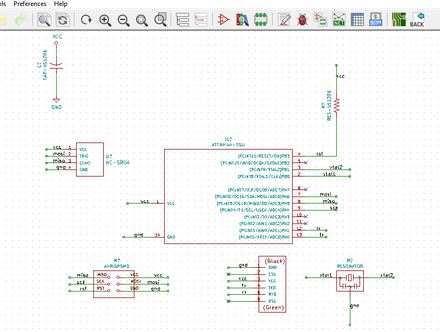 Scematic overview of my board
When all components where placed and connected i went to the next step. The first time using kicad it felt daunting. Now knowing the interface better the next steps was much easier to do.
I used the annotate function to order the different components. In this simple board design i have only one component each and it does not add to much but the more complex you make a design the more relevant this function is.
Next step is the electronic checker. The first time i received some errors in my design. By changing some wiring and name tag i could get rid of the errors. Only error 3 remaining which has to do with the power input. I could ignore this part and proceeded to the next step.
 the errors shown in electronic check
To be able to create the pcb design you first have to assign footprints to the design. Most of the footprints i could find in the fablab library. for the Sonar hc-sr04 i could use the library i downloaded before.
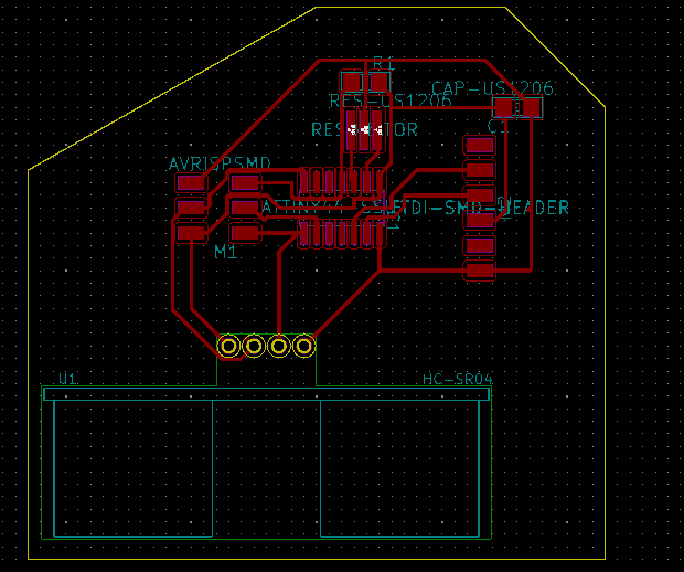
After that the most fun part of designing a board starts in the pcb menu of kicad. Connecting all the traces. First time it went surprisingly easy and i connected all the wires in 10 minutes. When trying to export the file i noticed the traces were very small. I forgot to set the design rules and a a result the line where just a quarter of a mm. First i tried to make the lines wider to the desired .4mm. The traces i could not place this way without overlapping each other. So back to the drawing board again.
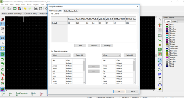 Forgot to set the design rules
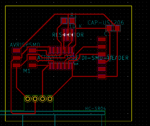
With the wider lines it turned out way more complex to figure out the puzzle. I had to rethink 10 times before i finally had all the traces connected. And ready to mill.
 finalized design.
Making the board
I exported the file first as svg to gimp to remove the alpha channel and set the bpi on 1000. i opened mods and first imported the inside. I inverted the image to make the right cutout. I learned the settings from the electronic production week
The milling went good till i made a mistake to open another mods to prepare the outside cut. That resulted in cancellation of the job. The job stopped on the spot. Never open a new mods when doing a job. I had to cancel the job and restart. I decided to use the same origin so the mill would take the same path. When the inside was done i cut out the outline with the .8 mm mill. I washed the board afterward and checked for shorts using the multimeter. I noticed that somehow between two paths the line was not cut. With the use of a knife i cut a opening in between. Then i checked again for errors. did not look nice but it seemed to work.
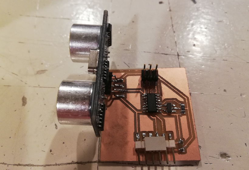
Then my soldering skills were tested again. Slowly get the hang of it but still have to work slowly. I managed to get all the parts on the little board. The only thing that turned out hard to place was Sonar. The device is intended for arduino use. I bended the pins to make the sonar fit on the board. Only then i saw my design error. I placed a path around the pins of the sonar. I had to place the sonar in such a way that it not interfered with the path. A not very stable connection as i noticed later.
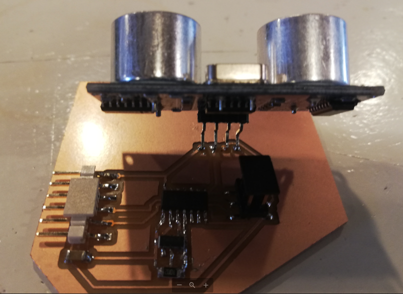 Sonar placed unstable and at the bottom the cut out path filled with soldering
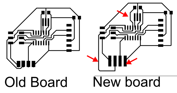
I tried to connect the board with the usbtiny to program and it did not recognize the board. I did some debugging to find where the issue was. With the help of the multimeter i noticed a bad connection between the sonar and the board. I wanted to push the sonar pin better to the board. The result was that the sonor broke of and it took the copper of the board with it. Now my board turned out useless. I decided to remake my board completly. No i could also fix the traces so the sonar would fit better on the footprint.
 new pcb design where i changed the traces so i would not encounter the same issues
In inkscape i enlarged the footprint for the sonar for a better fit. I made the traces now in a way that i had less chance of shorts.
 new design
This time the proces went much smoother. The board was milled quickly and also the soldering went smooth. Where the first design took me a long time to complete because of fixxing errors this one was done in a short amount of time. The end result was much more steady then the previous one.
Programming the board
Now it was time to go to the arduino IDE and use the boatloader. Very revealed to see it recognized the board. Now i would be able to proceed with programming the input of the device.
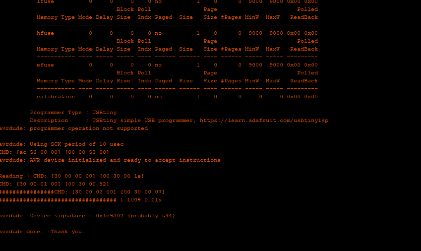 The device was recognized by the boatloader tool in Arduino IDE
My next challenge was to write a code for the device to recieve input on my serial monitor in Arduino IDE. I searched online for excisting code to get started. I found a code written for the arduino fretboard and used that one to see if i could recieve input. existing code
The difference with a ATtiny 44 is that you have communication with the rxd and txd. I had to modify the code to be able to recieve the data. Further i changed the declaration of the pins for the attiny. When this was set i tried to upload verify and upload the code to my board. I recieved a error with Serial not declared Turned out that since i was using a external library i had to write the serial command without the capital letter. After that i was able to upload the code on my device.
#include <SoftwareSerial.h> // import another program, a library, to communicate
#define rxpin 1
#define txpin 0

SoftwareSerial serial(rxpin,txpin);
This first part of the code i added to include the serial software and to be able to communicate with the serial monitor. This you do by defining the receiving pin (RX) and the transmitting pin (TX)
int rxPin = 1;
int txPin = 0;
int trig = 6;
int echo = 5;
long lecture_echo;
long cm;
In this line of code you initialize the different variables by the int command and give them a number corresponding to the pins you use. Here i changed the original code to correspond to the pins of the attiny 44a pin connections. The long command is used for extended size variables and can have a longer reach from -2,147,483,648 to 2,147,483,647. source
void setup()
{
  pinMode(trig, OUTPUT);
  digitalWrite(trig, LOW);
  pinMode(echo, INPUT);
  serial.begin(9600);
}
In the void setup you declare the input or output of the different variables. The trigger is a output since you send information to the device. The echo is information returning and therefor is a input. As soon the trigger goes from high to low the internal clock starts ticking. And the sonar will send 8 pulses. The serial begin function start the serial communication.
void loop()
{
  digitalWrite(trig, HIGH);
  delayMicroseconds(10);
  digitalWrite(trig, LOW);
  lecture_echo = pulseIn(echo, HIGH);
  cm = lecture_echo / 58;
In the loop you decide how often the sonar sends out a signal, Applying high or low voltage to the pin with a delay of 10 microsecond (can not be a longer time). With high voltage you recieve the input. The lecture_echo is when the pulse comes in on the high voltage. To calculate the cm you divide the incoming pulse (lectur_echo) by 58. Explained in the sonar section.
  serial.print ("Distance in cm: ");
  serial.println(cm);
  delay(1000);
}
To receive the data on the serial monitor u use the serial.print. The first line is the explanation which you will see by every data coming in. The second line is the data in cm. The delay is set to 1000 which means that every second you receive a new input.
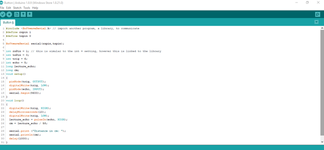 The code i used.
At first i could not see the input on my serial monitor. Turned out i switched the rx and tx cables. so the data would not transmit to the computer. When changing the rx and tx cables i was able to see the data coming from sonar and it was able to measure distance.
 Recieving input from my device
What i learned and what went wrong.
This week i spend most time on the hardware. Trying to design the board and making the board actually work. It costed me allot of time debugging and fixing design errors. In the end i have spend not so much time on writing code. Which is a shame since i really keen on learning this skill. Still need to find the logic in coding. The coming week i want to try to have my board ready quick so i can spend the majority of my time in coding the device.
I did learn some trick thanks to the errors. I see the importance in designing the pcb board. Create trace with enough space in between for optimal results. With soldering i have not such a steady hand and it helped me to use paper tape to help me solder the smallest components.