10. Molding and casting
| This weeks design | |
|---|---|
| Speculum | f3d fusion |
| Combinedtoolpathweek10 | sbp |
| Safety sheets materials for my design | |
|---|---|
| Addition15A | |
| Addition40A | |
| Addition B Fast | |
| Addition B Normal |
| Safety sheets materials in Fablab Amsterdam | |
|---|---|
| Smoothcast300serie | |
| smoothon121_30 | |
| smoothsil940 | |
| UreBond_II |
Groups assignment
Part of the groups assigment was to test the different pouring materials avaialbe and reading a safetysheet.
Safetysheet
Smooth cast 300 Fast setting -White The smooth on series 300, 300q, 305 and 310 part A have the same material data sheet. This warning is relevant for all these on the serie. The safetysheet is dividing the two components A and B. The safety sheet describes The safety measures you have to take when handling the material and also how the material reacts. There is a system which checks pourable materials.
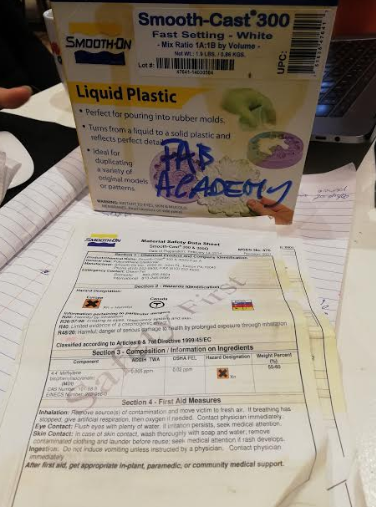 The safety sheet
HMIS = Hazardous materials identification system This system checks materials on four point. Health, Flammability, physical hazard and personal protection. Down here i give a small summary of the safety sheet i read.
- Component A.
H: Wear gloves. Dangerous for skin contact. Provide advice in how to handle when i Contact with component A
F: Flash: will start burning at temperatures from 128 degrees
It advice to wear goggles and gloves when using it. Don’t drink, eat or smoke. Use good hygiene. React with water. Stable with room temperature.
California proposition 65 : These products do not intensionally contain any chemicals which have been identified by the state of California to cause cancer, birth defects or other reproductive harm
Risk phrases r20 Harmful by inhalation. r26/37/38 Irritating to eyes./ Irritating to respiratory system./Irritating to skin. r40 Limited evidence of a carcinogenic effect. r48/20 Danger of serious damage to health by prolonged exposure.
Safety Phrases s1/2 Keep locked up/Keep out of the reach of children s23 Do not breathe gas/fumes/vapor/spray (appropriate wording to be specified by the manufacturer) s36/37 Wear suitable protective clothing/ Wear suitable gloves s45 In case of accident or if you feel unwell seek medical advice immediately (show the label where possible)
- Component B
No hazardous ingredients Non flamable –> flash point is 128 degree. The temperature the material might start to flame.
Wear gloves and glasses
Pot life 3 minutes cure time 10 minutes Use at 23 degree
Trying out the different pour able materials
With all the pouring i used gloves for protection and used the ventilated chamber we have at the Fablab Amsterdam. With the group we made one pour using vytaflex 50. This is a flexible urethane rubber used often for mold making. The ratio of mixing is 50/50 volume or weight of both components. You have around a hour to make you pour before the material starts harden. In normal conditions it takes around 16 hours to cure. We placed both components together and we stirred the two components mildly till it was well mixed. We made use of the vacuum chamber to get rid of air bubbles in the mixture.
The vacumm chamber at Fablab Amsterdam is a DIY device where you place the cup in a high pressure pan. Then the pan is closed by a thick plate of acrylic with two shafts. One shaft is used to vacuum the chamber and the other shaft for releasing air in the chamber. Between the chamber and the plat of acrylic there is a ring of silicone to make the object airtight. With the use of a air compressor the pressure in the chamber comes close to 1 bar. Then you wait till all the air bubble are gone. Then your mix is ready to pour.
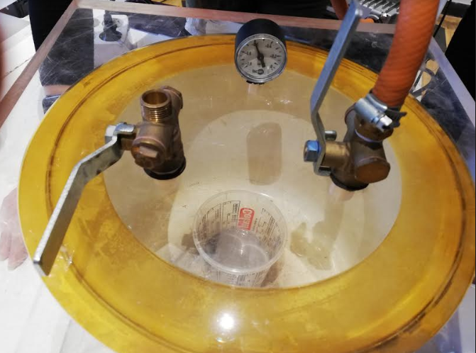 Vacuum chamber
We poured the substance in a wax mold we made using the cnc machine. We used release agent for the mold so the rubber would come out nice of the mold. The time to cure is 16 hours. It turned out a nice rubber substance which was easy to remove from the mold.
 The still fluid mix in the mold in a ventilated place
My first try was Smooth on pmc 121/30. It is a Urethane rubber which is soft and flexible. The two parts are mixed equal on volume or weight. When mixed you have a working time of 30 minutes before it start curing. This pouring went smooth and the substances mixed well. The result was a brownish colored substance which was flexible.
Next i tried the Smooth -Sil 940. This is a food safe silicone. The mix ratio is 10 -1 in weight. Here i noticed component A was a paste like substance. Not sure if the material should be like this. The b component was very liquid. I had difficulties in mixing the two components. I weighted the parts. Then i mixed them in a cup. The color turned pink. The end result was disappointing. I probably haven’t mixed the components properly since the endresult was sticky.
Further i tried the Smooth-Cast 305. Which was of the series i described on safety sheet description. The miz ratio was 50/50. I mixed the two together and i felt the heat of the curing. The material becomes extremely warm in the chemical process. I was afraid that it might melt through the plastic cup and i poured the material in on of the silicone molds. It was liquid and transparent the moment i poured. The moment the curing started it became white. The end result was extremely strong.
The last pouring i did was URE BOND 2. A flexible urethane rubber. The mix ratio was 50/50 by volume. By wieght the mix value is 100A -92B. The mixing went quite well end the end result was comparable to the pmc 121/30
Designing a Mold
When designing a two part mold using the cnc the are a few things to take in account. First the size of the milling bit effects the accuracy of the design. Secondly a 3 axis CNC machine can only make certain designs. It is not possible to mill in a angle which have a effect in the type of designs you want to create. Also the surface amount depends in what accuracy you can work. For this assignment we received machinable wax 14 cm by 8cm by 4 cm. The challenge is to create a two part mold to make a second mold.
Lot of ideas came to mind to design my mold. My favourite was a mold in a mold in a mold. But my final design was more practical. At the moment i am participating in a health prototyping event where makers and user come together to find solutions on healthcare. One of the groups is working to improve the female experience when going to the gynecologist. They searching for different methods to enhance the experience. One of them is the replacement of the speculum. The search is for a device that women can place themself for more feeling of control. They provide me a sketch for a first prototype. It seemed fitting within this weeks assignment which is making a mold. It will be a very first prototype without implications,
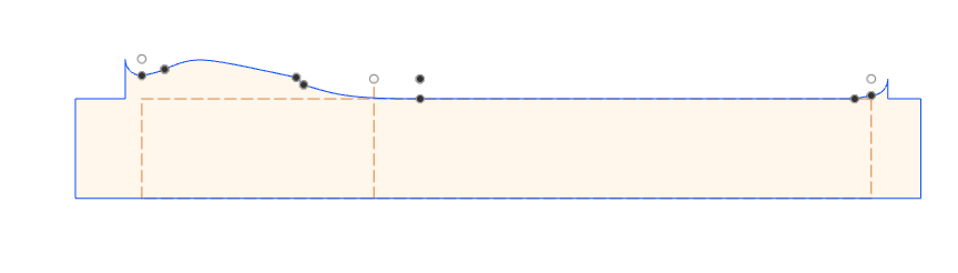
My first afford was loading the sketch in inkscape and draw the lines from the half of the design. I thought this design would be fitting to use the revolve tool in fusion 360. I took half the design and draw the rough outline. When i was ready i safed the sketch of the outline as a svg file.
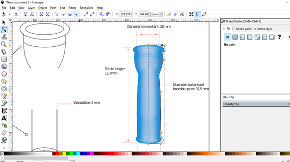
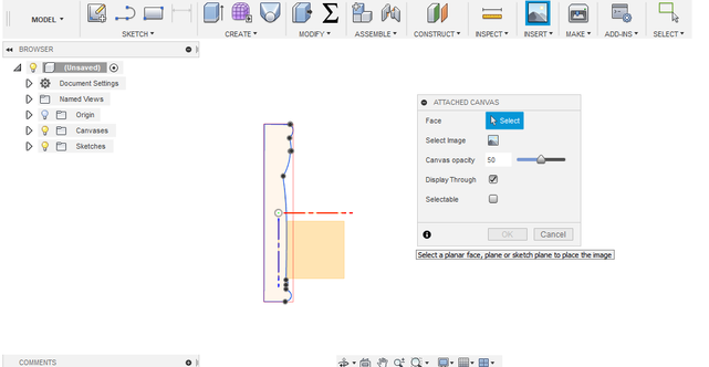
When importing the svg sketch in fusion 360 i wanted to dimension the lines. When i tried doing this the sketch got wel out of proportion and i had difficulties in setting the proportions of the curves correct. Change of plans. I decided to sketch the design in fusion 360. I used the svg file but instead of importing it i used attached canvas to be able to overdraw the design.
 using the canvas to sketch in fusion
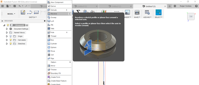
I used circle to create the curve shapes and with the trimming tool i removed the lines i did not need anymore. The with the option revolve i turn the sketch in to a solid model. I made the sketch in a way the mill of the cnc could touch all places in the design.
 Making a solid using revolve
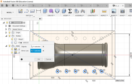
Now i had the model it was time to create a mold for the design. The design is symmetrical so i wanted to make the mold in such a way i just needed to make one side mold. Do two pouring and able to connect them to each other. To archieve this i cut my model in two using the spit body method in the tab modify. My design i made on the origin line so i could use one of the existing planes to cut my model in half. Now as a result i had a straight surface whic i could use as a sketch plane. The other halve i moved away using the move tool. On the backside of the design i started creating a sketch of the mold. The dimensions of my machinable wax is 8 cm by 14 cm. I used this as my outer layer of the mold. I used a of set of 5 mm to create a smaller rectangle as the beginning of my mold. Then i draw circles to connect the molds to each other i a later stage. Unfortunately my design is to big to make connection points on all sides. so i placed the circles where i could so that the milling machine could go around the connection points. When the circles where drawn on one side i used the mirror option in sketch to place them on a equal distance on the other side of the mold. Since my design was on the origin i could use the origin line a the mirror axis.
equal distance connection points
When this was set i extruded the bottom and the sides of the sketch to ensure the design is completly in the mold. The connection point i extrude on one side up 5mm and the other side down 5mm. Now i had myself a mold but now pouring connection yet. In the sketch they showed me the inside diameter must be 30 mm. I made a opening with this diameter and placed it on the width side of the mold so that would be the top side. I assumed this way it would be easier to remove the inside part out of the mold in the later stadium.
On the other side i made a outcut of also 30 mm diameter to place the inside part in. I though that might be a good idea to keep the inside in place. When not doing this the inside part might come loose when pouring and i want to have a 3mm thick wall on all sides. Now my outside mold was ready.
 The mold ready for the cnc
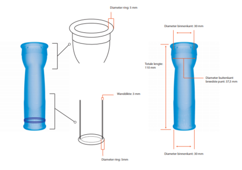
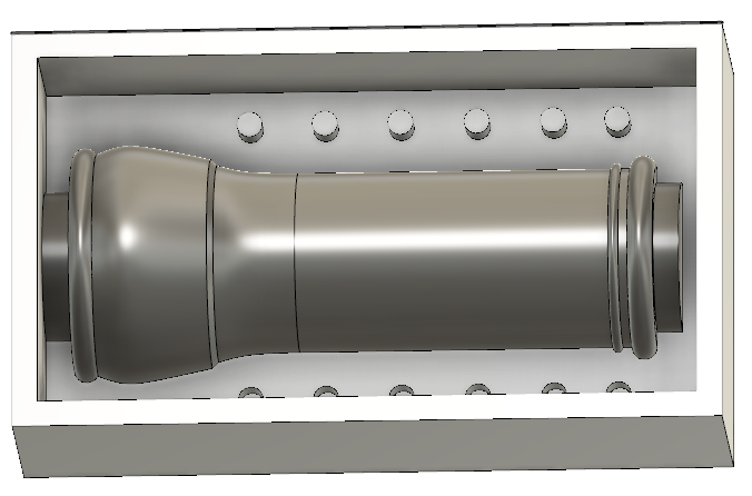
Now it was time to design the inside part. I decided to use the 3d printer for this one. The cnc has it limitations when it come to reach certain point or using angles. The pouring hole should be integrated with the inside design. The final design needs to be from silicone and i wanted to hide the pouring points. For the inside sketch i used the original sketch and put a ofset of 3 mm. i made the sketch in a way that the round curves should be visible in the final pouring. Further i added the connection point on the top and buttom.
 inside sketch
With the revolve tool i turned the sketch in a solid. Next step was to create holes for the pouring. I drew two lines from the top to the start of the ring. I curved the lines for smooth pouring. Since my design was on the origin the lines came nice in the middle of the design. On those line i created pipes. Since the pipes where created in a solid i could chose to use those pipes to cut my design. Now i had to holes in the inside design for pouring and for relieve of air. The hole mend for pouring i drew a bigger circle around it and extracted it in the design to cut it. This way the pouring can be more neat without spoil in the air hole.
 Pouring hole and ventilation hole
With the print option in fusion 360 i sended this design to cura to prepare for the 3d printer. The amount of detail i needed was low so i changed the setting to .15 mm per layer. I rotated the design so that the top with the holes would be top in the 3d machine. Wall thickness i set on 1.5 mm. I assumed this would be strong enough for it purpose. And further as cubic infill of 10 %. Since the object i long i choose for a large brim of 20 mm. I was not sure about support. I hoped it could handle the small overhang.
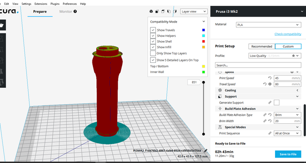 Ready for 3d print
The machine setting of the 3d prusa printer i left on default for pla. I cleaned the headed bed before starting the print. The print came out really good. a small error at the curve below but all in all i assume it will do its job.
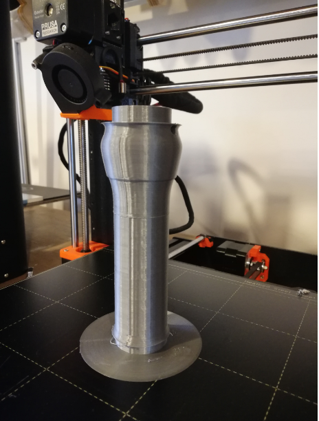 Result inside part mold
Partworks 3D
In the week of make something big we became acquanted with the cnc milling machine. Then we put the focus on partworks and how to work with vector files. This week we explored the 3d posibilities of the machine. With a 3d design u use the full potencial of the cnc, moving the z axis while moving on the X or y axis. The mold i made for this assigment in fusion i uploaded in the partworks 3d as a stl file. In the software you go through different phases to make the design ready to mill.
First step when uploading a stl in partworks 3d is the orientation. How you want to place the model and is it directed to the X and Y axis. Here you also see the dimensions of your stl design.
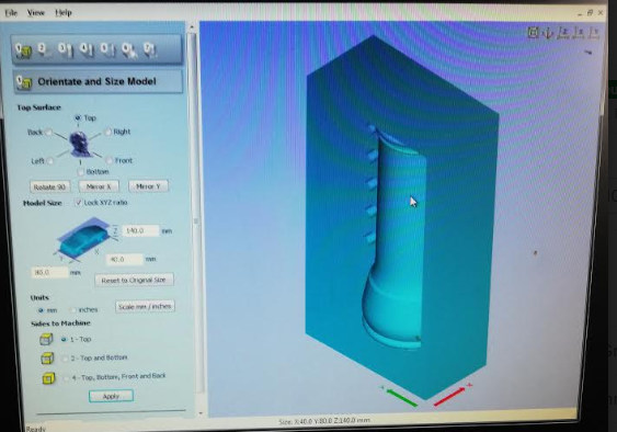 placing the stl file
In the next menu material size and margin you decide where the z axisis placed and where the x andy origin should be. In this menu you further decicede the margin around the model. In this case i am only interested in the mold and did not want a cutout around so i placed all margins at zero. Also you have the possibility to place tabs in the design. For the mold assigment i could skip this part.
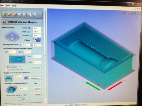 * creating the margins
In the roughing toolpath you decide the milling bit you are going to use and depth and speed of the machine. I kept my setting with what i learn in the week make something big. The depth at max halve the diameter of the drill. I used a 3 mm endmill for the roughing toolpath and also the finishing tool path. Kowing i could speed up later on i chose 35 mm per second for a start. The spindlespeed i brought back on advice of our instructor to 6000. At the fablab Amsterdam they safe the wax remains for futher purpose. With spindlespeed on 6000 the pieces won’t fly away that much. I also effect the temperature of the mill. You do not want the wax to melt on your mill. The roughing toolpath mills away all the empty space without getting in to detail.
 rough tool path
In the next menu there is the finish toolpath. This will result in a smooth finish of your model.In the previous menu you could use a stepover over around 50%. Here you want a much smaller stepover for a smooth end result. I did make much changes since i used the same mil;ling bt of 3 mm.
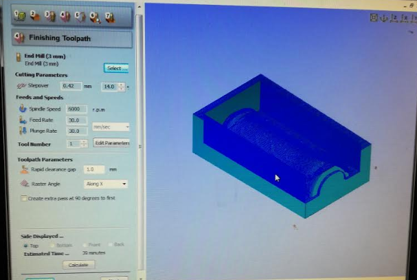 finish toolpath
The next menu is cut out toolpath. I did not have use of this menu for this assignment. I just wanted a nice looking mold. So i skipped this session. But this menu enables you to make a cut around your piece.
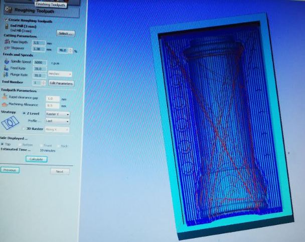
In preview menu you can see the path the machine will take to cut out the rough and finnish toolpath. I is a good tool to check your design. Did you left anough margin around the model you can see thanks to the preview menu. In designing i took the size of the mill in account and did not had to alter something in this menu.
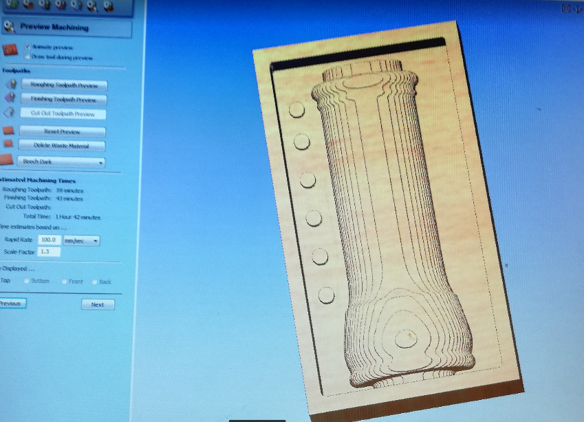 preview of the rough toolpath
In the last menu you can safe the files for the shopbot. When using different drills its wise to safe them different so the machine will pause and you can adjust the mill size. I decided to stick with one mill so i safed both jobs (rough and finish) in one job so the machine would do the job in one run. To get my mold cuth out in these settings it would take one and a half hour.
Milling the mold.
First i had to place the wax on the cnc workspace. I used double side tape to place the wax block correct on the board. To ensure the block would not move i placed wooden part around the object and screwed it to the sacrificial layer.The design i had in mind was pretty tight in the mold so i made sure the x and y axis where perfect align.
The procedure is the same as with two 3d milling. You place the drill you want. Set the origin right. Normally you put on the ventilation. Since we want to reuse the wax i skipped this part. I set the origin first on the absolute zero of the machine and then changed it to the desired location. Using the metal bar i decided the z axis.
When all origins where set and nothing layer on the cnc board i turned on the key to start the spindle. After a small warming up i loaded the shopbot file and pressed start. The machine digged right in to the material and the mill broke instantly. Oops. I stopped the job straight away and move the z axis up. Then i removed the key to stop the spindle. What went wrong. I was confident i followed all the steps regarding the x,y and z axis. But how was it possible that the mill went in to the material for 15 mm. I rechecked my design file and this should not be happening. Then i thought it might be the mill that slighted out of the collet. But i did turn the collet tight before starting the job.
It turned out that the collet i used was a metric collet and therefor was slightly bigger and did not hold the mill tight as it should. This was my mistake. I used the machine after someone else did and i checked the mill size and assumed i could use the same collet. Learned my lesson. Never assume when using the CNC machine. Double check everything. I changed the collet and placed a new 3 mm mill in the collet. I made sure the mill stood out long enough to reach all point of the mold. I reset the origin and set the new origin again. When ready i uploaded the file and pressed start again.
Now the machine worked according plan and started with the rough path. I checked the first layer and decided to change the origin by a small margin. My design just fit on the block of wax and i noticed that with the current origin i had a minimal margin on one side. I was afraid that the boundary would not stay in place or break. I changed the origin by a 3 mm and restarted the file again. Now the design was nice in the middle of the block and had edges of approximately 5 mm.
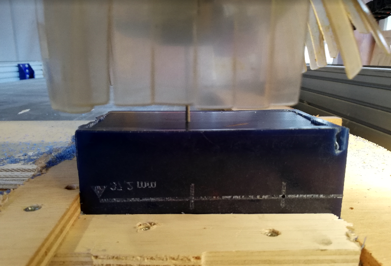 On the right side you see the error with the collet.
The whole job took around one and a halve hour to finish. Because the machine ventilation was of it was hard to see how the mold developed. The wax mold was full of small cut out pieces wax. So it was a patient wait and hoping the mold came out nice. When the job was finished i moved the mill away from the workingfield and turned of the spindle and machine. I collected the wax pieces in a bag and removed the wooded structure i build around it. Now it was time to inspect my mold. I was please with the result. Up to the next step.
 Mold ready, now collecting the was pieces
Pouring the Wax Mold
The final design needs to be skin friendly so i decided to make the mold of high quality addition silicone. It the same silicone i used to create jewelry. I want to be able to take the silicon in a easy way out of the wax mold so i used a shore of 15. This is a highly flexible silicone which can be stretched allot. This silicone works with component A and B and a mix ratio of 10 - 1. The curing time depend with this material on the b component. You have a fast and normal hardener. The fast you have a working time of 15 minutes before the curing starts. The normal has around a hour working time and curing time of 12 hours. I was eager to quickly create two molds so i mixed the fast and normal around 50 % to get a in between working time.
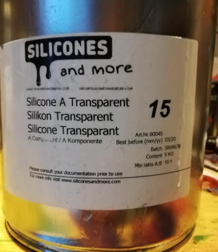 The A component of the addition silicone 15 shore
I mix the two components based on volume. I used a measuring cup and filled it with 175 ml silicone A. Then i added 10 ml B fast and 7.5 ml B normal. I measured before the volume of the mold using water in a measuring cup. In total i came on 180 ml water. I wanted to use slightly more. You don’t want to pour the mold in two different layer so i played for safe. With a spoon i gently mixed the two components.
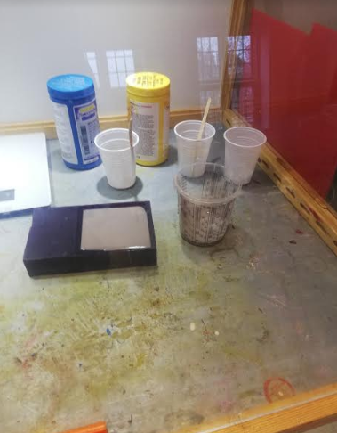
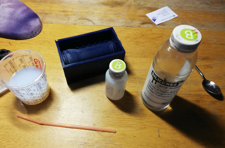 The matials for pouring
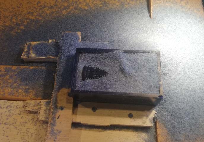
With a straw i blew away remaining bubbles. I had i mind that the curing time is rapid thank to the mixture so i did had to do the pouring in time. At first the material is very liquid, the moment it starts hardening it becomes more sticky. I removed the big bubbles but there where still small bubbles remaining. I decided to start pouring and with the use of a straw remove the bubbles in the mold itself. I was not sure how easy it would be to remove the silicone out of the wax mold so i placed two pieces in the mold to make it easier afterwards to remove the silicone. This way you can reach underneath easier to remove the vacuum underneath.
For about 5 minutes i could get rid of the remaining bubbles and then the harding proces started. There where still a few bubbles remaining but nothing more i could do. It took around a hour for the mold to be hardened. Before taking out the silicone i felt the measuring cup if the silicone was hardened.
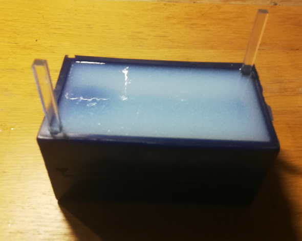 the mold filled with silicone and two parts placed to remove easier afterwards
Now i had one side done and i redid the procedure. This time i was more gentle in the pouring and less bubbles remained. When the second pour was done i had all the parts to start making the final design.
Making the final design
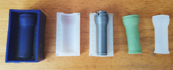
First i checked how well the 3d part fitted inside the silicone mold. Revealed to see it was a good fit. All the point connected nice. Also the fit with the two mold where good.
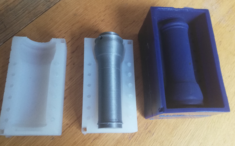 all the parts
I did want to build extra support around the mold so the mold would stay in place nice. Silicone is liqued when pouring and i did not want the silicone to escape the mold. I cutted four boards and with a gluegun i place them on a plate of accrylic. All the side i used the gluegun to get a tight box. Now the mold was set tight in the box. I wanted to do several pourings so i made the box sligthly less tall then the mold so it would be easy to take the silicone mold out after pouring.
Next step was to prepare the mold with white vaseline so that the pouring wont stick to the mold. I will be pouring silicone in silicone so this step is very important. If you do not do this the cast will be stuk in the mold. I used a small brush to spread the vaseline evenly over the mold.
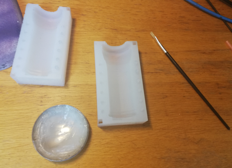 greasing the mold with vaseline
After this i placed the two sides together with the 3d printed object in the middle. I placed it in the box and added a funnel to the pouring side. This way i spoil less silicone and i can pour more in one go. I had to do a bit grinding on the funnel to make it a good tight fit.
 Ready For the first pour
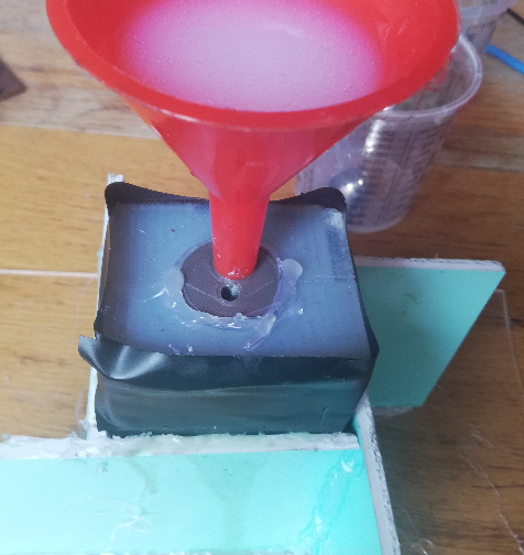
Now everything was set i prepared the pouring. My wish was to do a few pourings this week so i decided to let it cure quicker. Just for ecstatic reason i added color to the silicone. I use skin friendly pigment to color the silicone. I made a mixture between green and white. Always be gentle with the amount of pigment you add to the design. When overdoing this the silicone might not harden as expected. Again i added a mixture of B fast and B normal to quicken the process. I used silicone shore 15 for the first pour. I expect that 15 shore is to soft for the purpose but i wanted to check how the endresult would look like. I poured it in the funnel and saw it slowly filling up the mold. To slow because it started hardening to quick before the mold was completely filled.
 first pour in the mold
So i took out the failed first attempted and checked how the pouring went. Besided that the design did not came out completly i was not pleased with the edges where the two molds come together.It did came easy out of the mold so that was good. Back to greasing the mold. Everytime you want to do a new pouring make sure to grease the mold. To prevent the silicone slipping in the edges i used tape to keep the mold tight and placed the mold back in the box.
 inspected my first failed pour
This time i only used the b component normal to pour the mold. I wanted more time for the silicone to settle before hardening. Still being stubborn and want to do multiple pourings i waited till the mold was finished. This you could see the moment silicone was coming to the second hole. I waited a hour till i felt the silicone was in the hardening process. Then i took it gentle out of the box and placed the mold on top of a pre heated oven. Silicone hardens more rapid when the temperature is higher and this way you can reduce the waiting time.
 the mold is filled and the silicone come out of the second hole
I gently remove the mold to check the design. This time the design came out completely. The design i removed from the mold and left on the 3d printer inside mold. I still had to cut the filling holes and some silicone found its way on the top of the inside. There i realized i small fault in my design. It would have been better to print the 3d inside part with a cap where the surplus of silicone is stored. The amount that comes out of the mold. Now it went back in on top of the design. It is not a major issue but the result could have been better.
 Second pour is complete, checking for faults
After removing the second design i used the scissor to get rid of the remaining edges. The design is functional and feels strong and stretchy. I expect for the purpose it is to flexible and when adding pressure it bends.
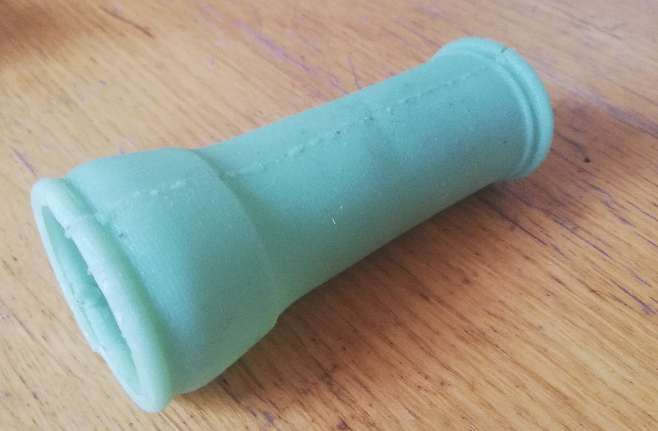
My final pour was a addition silicone with shore 40. Which is less flexible then the shore 15. This time i did not add any color to the design. The request for the protoype was to make it transparent. Complete transparent is with this material not possible, it is more translucent. The material is also thicker then the silicone shore 15 before pouring.
I changed one thing before pouring in hope of a better result. I used the gluegun to close the top of the mold so silicone would not flow back in to the mold.
 fixing the top with gluegun and translucent silicone shore 40
The day after i took the new pour out of the mold. Happy to see the whole deign came out. There are a few small bubbles in the pour but the design looks decent. I expected to see some bubbles. The material is much thicker than the 15 shore and the pouring holes and releave hole are only 5 mm. I a next try with 40 shore i want to use a long curing time and use the vacuum chamber at the fablab to get rid of all the bubble before pouring. Maybe also cure the silicone in a cold place to have a longer curingtime so that bubbles have move time to resolve.
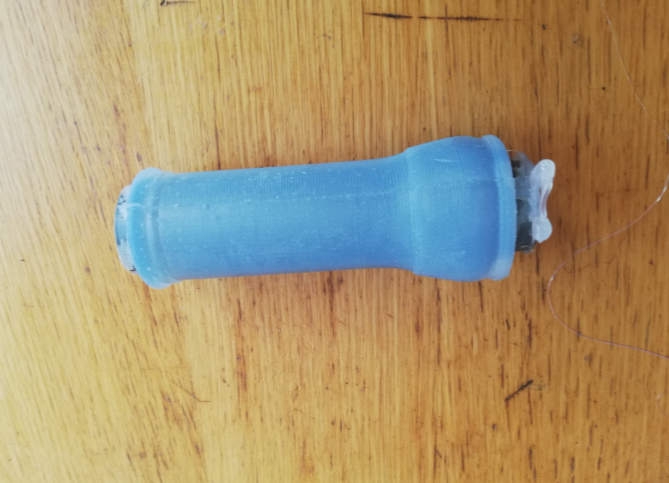 Last pour with the 3d part still in there
The last pour feels much stiffer than the previous one. I expect that the last design is more functional thanks to its stifness. The design is translucent and you can see more though the material which makes it also a more suitable design for its purpose.
What i learned and what went wrong.
I played around in the past with making molds but it was my first time using the machines to create the mold. Which was a fun experience. I love the puzzling part when creating a mold. Brainstorming in how a mold would function best. Fun to create a 3 part mold. I do see improvement in how to optimize the mold. Next time i would be more patient in creating the silicone moulds. If i would have used the long curing time the silicone molds would have been nicer. The surplus cap on the 3d printed part could resolve the spillage inside the mold. But considering the time i am pleased with the design. It feels strong and is stretchable.
A mistake i made was using the cnc machine. I should have double checked the size collet before placing the mill. This time it did not had serious impact but lesson learned. Always check all parts before starting a job. It was a fun weeks exercise.