14. Networking and communications
The individual assignment of this week is to design, build, and connect wired or wireless node(s) with network or bus addresses. And the group assignment is to send a message between two projects
Files, planning and tools
Files
- Group assignment: node 1 file
- Individual assignment: Treenetwork node 1 file
- Individual assignment: Treenetwork node 2 file
- Individual assignment: Treenetwork bridge file
- Schematics Neopixel board
- PCB routing Neopixel board - kiCad
- Traces Neopixel board
- Outline Neopixelboard
Planning
- Group assignment and its documentation
- Do a test with Neopixels and the Arduino Uno.
- Figure out the programming code of the step response
- Figure out how I can set up serial communication.
- Design a board for the Neopixel
- Connect the Neopixel board as node in the network.
- Nice to have: Neopixel board reacts to step response
Tools
- Mods
- Roland Modela MDX-20
- Arduino Uno
- Arduino IDE
- Breadboard and components
- Illustrator
Link with final project
For this week I want to see if I can combine my input device with my output device through a wired network. I will use the step response board from the input devices week and I want to connect it to a Neopixel strip, and if possible I want to control each Neopixel separately. It turned out that this was a bit too much for this week, due to my programming skills and the time I had and it took me to understand each part.
Research and inspiration
For this week I was a bit confused what to do, mainly because of time issues and possible links with final project. In the beginning I thought I would create a bluetooth network this week. So I researched some options, it seemed a nice option. However in the end I decided that this is not something that I will use in my final project as priority. In addition, I looked into the use of Neopixels. In the end I decided to use Neopixels with serial communication.
Links used for Neopixels.
- Datasheet Neopixels (WS2812B)
- Adafruit Neopixel uberguide
- Adafruit bluetooth neopixel goggles
- Mike Kohn WS2812B setup for ATtiny85
- Datasheet ATtiny85
Links used for networking and communication
- Arduino tutorial serial
- Arduino CapacitiveSensor Library
- Neopixel with Arduino controlled bluetooth by electronicGURU
- ATTinyCor pinout ATtiny85 and Attiny44
What we did – Group assignment step-by-step
We used our boards from the Electronics design week to create a serial network.
 Sketch bridge and node by Emma
We based our code on the example by Emma. She gave us a more detailed lesson on networking and communications this week. Joey wrote the program for his board as a bridge and Anne and I each wrote the program for the two nodes, we used Rutgers and my board as node 1 and node 2.
The code I wrote for our group assignment.
#include <SoftwareSerial.h>
#define rxPin 0
#define txPin 1

SoftwareSerial serial(rxPin, txPin);
int v = 0;
int ledPin = 7;

void setup() {
  // put your setup code here, to run once:
  pinMode(rxPin, INPUT);
  pinMode(txPin, OUTPUT);
  pinMode(ledPin, OUTPUT);
  digitalWrite(ledPin, LOW);
  serial.begin(9600);

}

void loop() {
  if (serial.available() > 0 ) {
    // read the incoming byte:
    v = serial.read();

    if (v == '1') {
      digitalWrite(ledPin, HIGH);
      delay (1000);
      digitalWrite(ledPin, LOW);
      delay (1000);
      digitalWrite(ledPin, HIGH);
      delay (2000);
    }
    else {
      v = 0;
      digitalWrite(ledPin, LOW);
      delay (1000);
    }
  }
}
We managed to create a network between our three boards. The bridge sends out 1 or 2; node 1 response when it gets a 1, and node 2 response when it gets a 2.
 Group assignment: network with 2 nodes
What I did – step-by-step
To get a better understanding of how each element in the network acts and how to connect these with each other, I decide to take small steps. First I tried to get the Neopixels working with an Arduino Uno. Followed by first understanding the step response board (treeboard), using my computer and the serial monitor to check if there’s communication for each board before connected all the boards together.
Step 1: getting to know Neopixel
Before I started this weeks assignment I wanted to get to know the Neopixel, as Henk mentioned this would be a better option for my final project than a normal RGB-led matrix. Emma explained me the difference between a normal RGB-LED and a Neopixel. A normal RGB-LED has four connections: R(ed), G(reen), B(lue) and a common anode. A Neopixel is a RGB-LED integrated in a driver chip. It has four connections as well but for the Neopixel these are: VCC, Ground, data in and data out. The data in and data out part shows that these Neopixels connected, in a strip for example, are actually a small network. The advantage of these driven LEDS is that you can connect a lot of LEDs to one pin.
![]() Difference RGB-LED and Neopixel
Difference RGB-LED and Neopixel
I followed the Neopixel überguide tutorial by Adafruit to setup the basic connection with an Arduino Uno as described on their website.
![]() Neopixel basic connection by Adafruit
Neopixel basic connection by Adafruit
Instead of a 5V power supply I used the Arduino Uno for 5 Volt. And in stead of a 1000 uF capacitor I used a 100 uF capacitor, as I didn’t have a 1000 uF version and because I thought that the Arduino Uno would already be better in regulating the 5V power supply. As mentioned in the tutorial I used the example sketch strandtest in the Arduino IDE to test if the Neopixel would work and they did.
![]() Neopixel test setup with Arduino Uno
Neopixel test setup with Arduino Uno
The setup and example code works, this gives me a bit better understanding of and confidence about how I can use the Neopixels.
Step 2: using my step response as bridge
The next small step was to see if could use the step response (treeboard) from the input devices week. So first I had to check if it still worked. After wiring it correctly, it did! I could see the numbers from the patches on my screen, I though that this is already serial communication, so my next step is to see if I could give it an address and sent this to to node. This wasn’t as easy as I thought. I used to following steps to get the serial communication to work.
Reproducing the group assignment with my own board
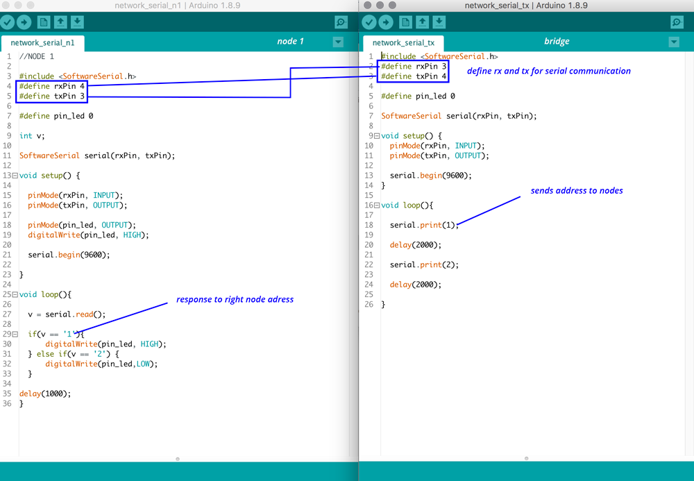
To setup the serial communication between the boards I decided to first see if I could reproduce our group assignment with my two boards. I uploaded the code of the bridge, with a change in rx and tx pin, on my treeboard and I used the same board I used in the group assignment as node 1. This worked like a charm.
 Reproducing the group assignment with my own boards
Setting up serial communication with the step response board.
The next step for me was to see if I could use the measurement of my step response board, and sent these to the node to let the light blink. The biggest challenge for me was to figure out the programming code of the step response. I understand how it measures and what the measurements are, however to change or edit the code to add serial communication took me long to figure out. Therefore I decided to look into other options.
- Because I knew it would take me too long for the time I had this week, I decide to rewrite the code and use the CapacitiveSensor library by Arduino. I first used a sample code to test if this would work. However it turned out that this library is too big for the ATttiny44. So it didn’t work.
- Next step was to find an example code that was easier to understand and didn’t use the library. I looked at documentation of previous years to see if someone was able to program the Attiny44 without the CapacitiveSensor library. I found the documentation of Pauline Varley, she had an nice example. So I used her code to see if it would work for my board as well. In the end this didn’t work. I looked into her code and there was one part a bit unclear. She used the A-ports while I think I use the B-ports. However when I tweaked parts this would work.
- So I went back to what I knew worked, and looked again into the c-code from my own Step Response. I tried to tweak parts of it and see if I could add the serial communication part from Neils example of this week. However it didn’t work the way I thought and I didn’t have the time to figure this out.
- In the end these steps already took me a lot of time while I also wanted to design my own board with Neopixels. My programming skills are still really basic to edit this file. So skill and time wise, I decide, for this week, to keep the treeboard only as a bridge and won’t use the measurements of the input. I do want to figure this out for my final project.
Step 3: Designing and making my Neopixel board
I used the schematics of the test board for my Neopixel board, and double checked it with the one by Michal Kohn. I added an extra 3x2 header because this gives me the flexibility to add more Neopixels later.
Components used:
- ATtiny 85
- resistor 10k
- capacitor 1uF
- resonator 20 Mhz
- Neopixel
- capacitor 0.1uF
- resistor 330 OHm
- ISP-header
- FTDI-header
- 3x2 header for connection Neopixel strip
![]() Schematics of my Neopixel board
Schematics of my Neopixel board
I added these components in KiCad and created my schematics. The routing of this was really easy as this board is similar to the one from the electronics design week.
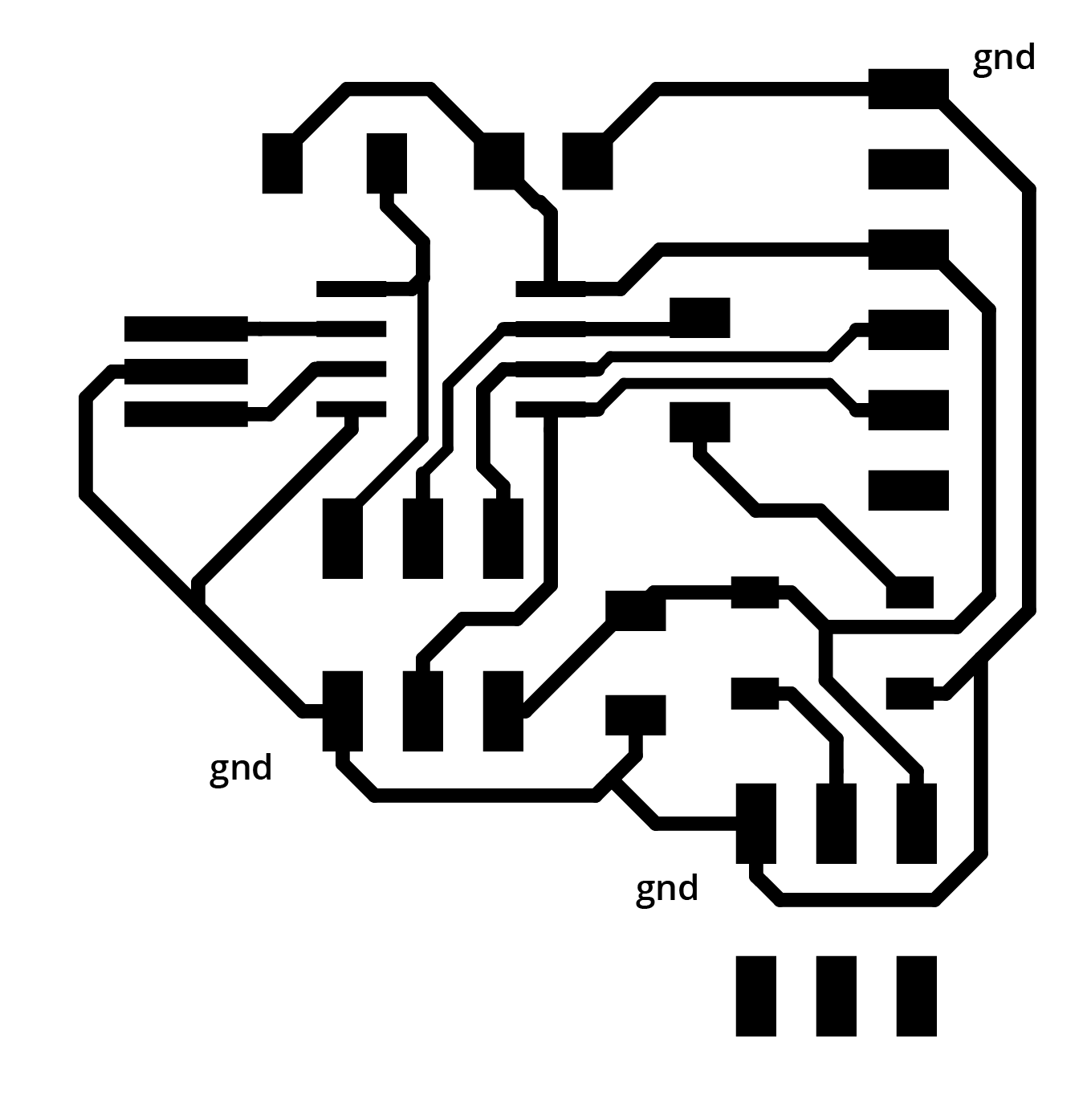
![]() Routing of my Neopixel board
Routing of my Neopixel board
Since the input week I added illustrator to my work flow of transforming the SVG to PNG file. This gives me more control on the shape of the board.
 Step 2: importing a SVG in Illustrator gives a blob
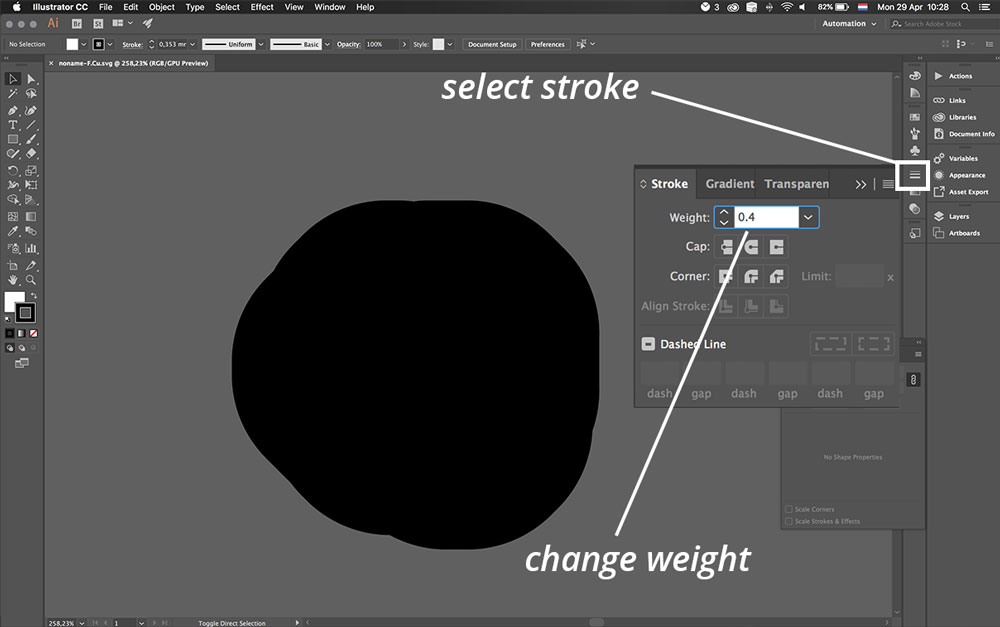
- Open SVG in illustrator.
- This gives a big black blob. Select everything.
- Go to stroke option. And select weight.
- Use the same numbers as the design rules. So in my case 0.4 mm.
- This also gives the opportunity to make some parts a bit thinner when needed.
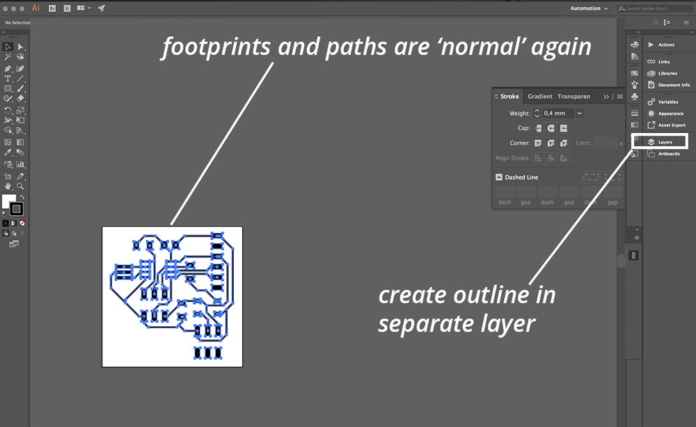
- You can use the pen-tool to create the outline. For input I created a tree, and output week a leaf. This time I just created a square and added gnd so I know which pin is ground for the headers.
- Make sure to add the outline in a separate layer
- Export both layers as png. Don’t forget to tick the Use Artboard option in the export menu.
- I use these PNGs in Mods. I always invert the PNG in Mods to keep my work flow the same.
 Step 5: Result after changing stroke weight to 0,4 mm
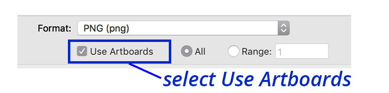 Step 8: Make sure to select Use Artboard when exporting the PNG
Step 4: Milling and soldering my board
![]() Milling and soldering my board
Milling and soldering my board
This went really quick this week. I used Mods the Modela to mill my board. I double checked my settings and the work flow with the documentation, I getting used to this whole process. Soldering went smooth, I used the datasheet of the WS2812B (Neopixel) to double check its placement. One small thing went wrong I accidentally connected the DIN to VCC of the Neopixel. But this was easy to fix with a heat gun and re-soldering.
![]() The orientation of the Neopixel can be found in its datasheet
The orientation of the Neopixel can be found in its datasheet
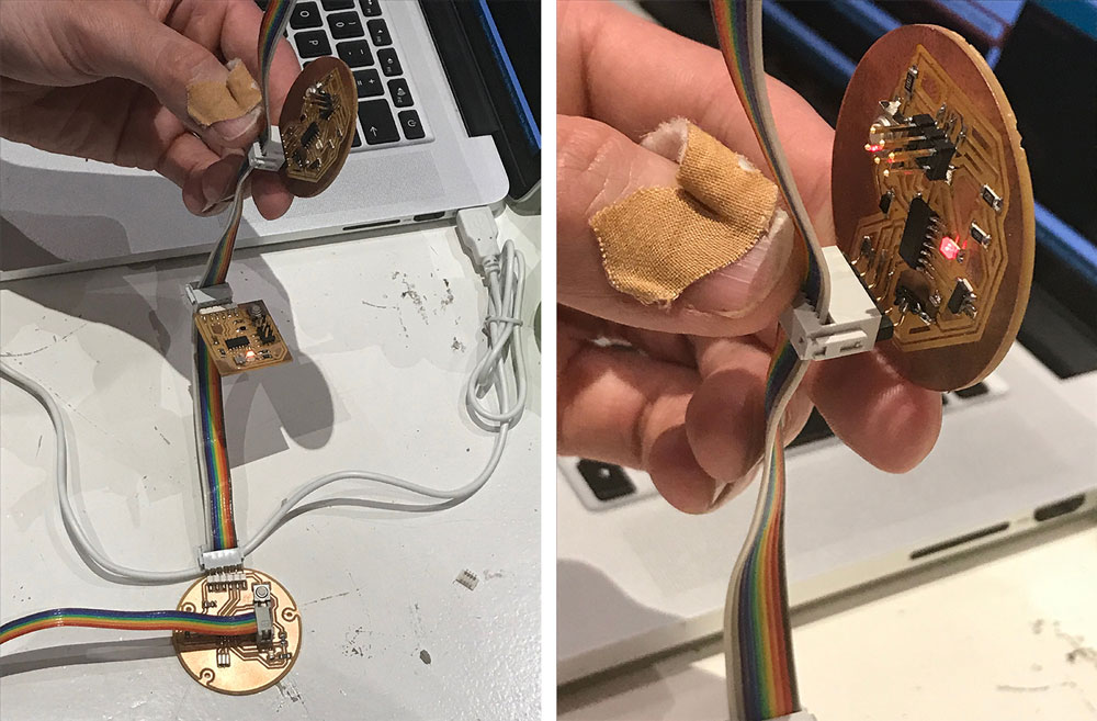
Step 5: testing serial communication with my Neopixel board
When I finished this Neopixel board, I first tried out if I could set up serial communication with my Neopixel board as a bridge, so I uploaded the bridge sketch by Emma. This worked straight away.
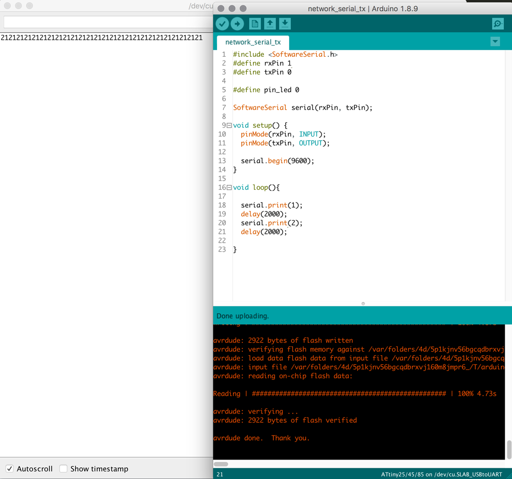 Serial test Neopixel board as bridge
So the next step was to see if I could use it as a node. So I uploaded the node sketch to see what would happen. This didn’t work, however it turned out that I connected the Data In Pin (DIN) of the Neopixel to the VCC and that’s why it didn’t work. When I fixed it the Neopixel board worked like a node. The Neopixel turned on when it received a 1.
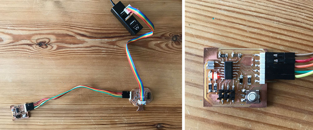
Step 6: connecting my tree board with two nodes
My final step was to connect the tree board as bridge with serial communication to node 1, the board from electronics design week, and node 2, the Neopixel board I designed this week.
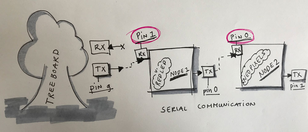 Sketch of serial tree network
Connecting each node separately
First I connected each node separately, so first the Treeboard bridge to Node 1. Followed by connecting the Treeboard bridge to Node 2. This worked so I know the bridge and each node works.
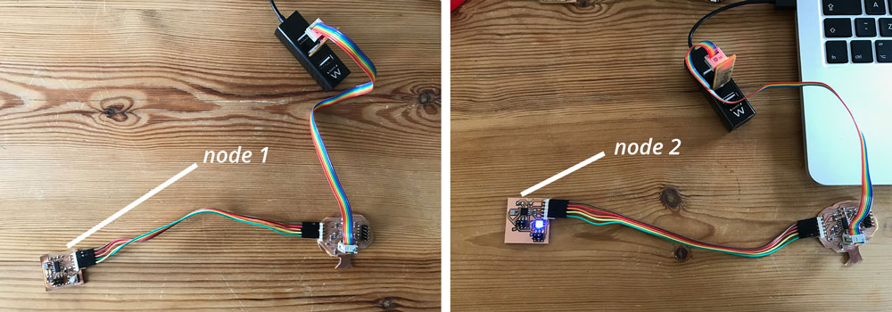 First testing each node separate
Connecting the nodes together
The next step was to connect the nodes together in the serial network. This didn’t work straight away, because the way I defined TX and RX and the way the wire worked (as described in the section ‘what went wrong below’) was a bit confusing. But I managed to set everything in line and my serial communication works.
Serial network tree board
Step 7: fine tuning the code
I tweaked the programming codes while I was testing each node. So when I had everything working I wanted to fine tune the programming part. I wanted to make it more clear in the code that I use addresses in a network. So I added a node_id in the code for both nodes. In addition, I redefined the int value to int bridge_communication' . This was also a way for me to get more familiar with the coding and changing and tweaking parts.
#include <SoftwareSerial.h>
#define rxPin 1
#define txPin 0
# define node_id '1'

SoftwareSerial serial(rxPin, txPin);
int bridge_communication = 0;
int ledPin = 7;

void setup() {
  // put your setup code here, to run once:
  pinMode(rxPin, INPUT);
  pinMode(txPin, OUTPUT);
  pinMode(ledPin, OUTPUT);
  digitalWrite(ledPin, LOW);
  serial.begin(9600);

}

void loop() {
  if (serial.available() > 0 ) {
    // read the incoming byte:
    bridge_communication = serial.read();

    if (bridge_communication == node_id) {
      digitalWrite(ledPin, HIGH);
      delay (500);
      digitalWrite(ledPin, LOW);
      delay (500);
      digitalWrite(ledPin, HIGH);
      delay (500);
      digitalWrite(ledPin, LOW);
      delay (500);
      digitalWrite(ledPin, HIGH);
      delay (1000);
    }
    else {
      bridge_communication = 0;
      digitalWrite(ledPin, LOW);
      delay (1000);
    }
  }
}
What I did wrong – and how I solved it
Neopixel wouldn’t light up
When I connected the Neopixel board as node the Neopixel wouldn’t light up. To troubleshoot this I took the following steps.
- I knew the Attiny was working because the bridge sketch worked and gave serial communication. So it wasn’t the chip,
- My guess was that there was something with the connection the the Neopixel as this one wasn’t working. I used the multimeter to check each pin of the Neopixel.
- With the multimeter I quickly found that I soldered the footpath of Data In (DIN) to the VCC.
- I used the heat gun to remove the Neopixel from my board.
- I had to use a knife to disconnect these parts and to make sure the two parts weren’t connected. I double checked this with the multimeter.
- I soldered the Neopixel back on.
- When I connected my board to my computer the Neopixel lighted up straight away. Problem solved.
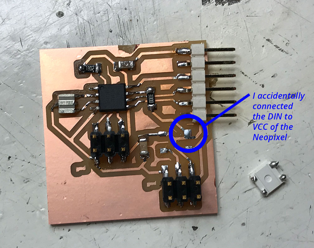 Soldering fail: I connected the VCC to DIN
Confused with RX and TX
When I had my three board to connect I really got confused with the combination of RX and TX. The main cause was that my pins were just the other way around for my node 1 board and my node 2 Neopixel board. To get a better understanding of how the network communicates. I sketched it down on paper to give me visual reference.
Sketch of serial tree network
I triple checked each pin with my previous documentation and the overview of pin outs of ATTiny85 and ATTiny 44.
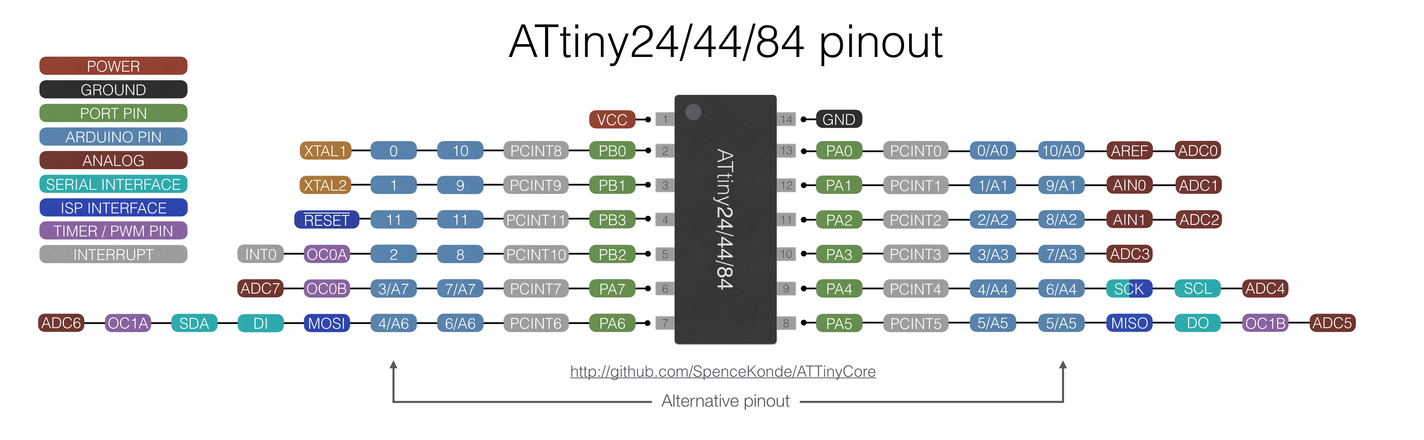 ATTiny44 pinout
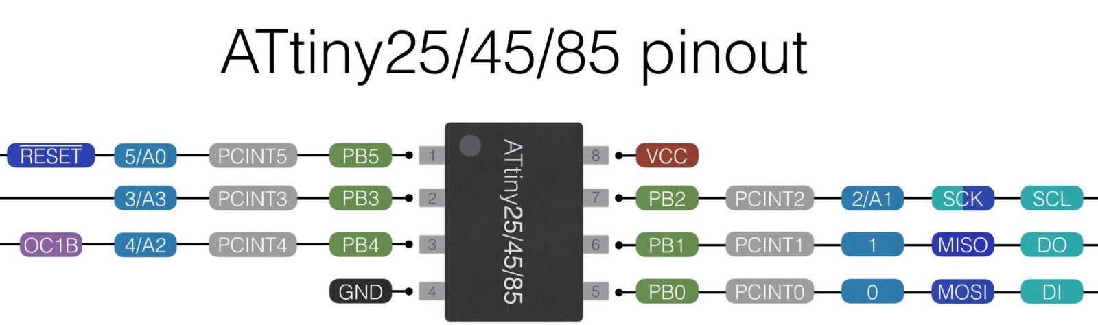 ATTiny85 pinout
I realized that for the two nodes the TX and RX are just the other way around. I confused myself in the code. In the end it was an easy fix.
Node 1
- RX: pin 1
- TX: pin 0
Node 2
- RX: pin 0
- TX: pin 1
Working with node_id
I rewrote the code to work with a node_id because I thought that would fit more to the assignment of this week. However when I uploaded the file to my board it didn’t work. It turned out that the serial.print function send a char in stead of a number. So I added the brackets ‘1’, this worked.
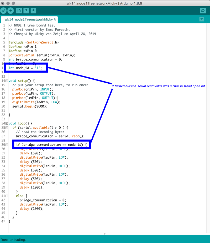 Changing the node_id in the code
Turn off Neopixel
I had some problems of turning of the Neopixel as the digital.write(low) option didn’t work. I edited the example sketch for Neopixels, strandtest, by Adafruit. While looking at the part of the code I realized that it sets the colors and I thought that if I would set all colors to zero this would work. So I added
colorWipe(strip.Color( 0, 0, 0), 0); // off
to the sequence and this turned off the Neopixel.
What I learned
How to setup a small serial network
This week I learned a lot about networking and communication and how to setup your own network. I decided to keep it simple which worked out really nice for me. Because this way I created my own small network, and I see possibilities how to add this in my final project and how to tweak this myself.
How to manage time
This week I was short in time because I was still catching up with the molding and casting week and I realized we had one day less to finish this week due to May first. In the end I still I spend a lot of time trying to figure out the code from the step response which was frustrating as I found it difficult to understand how to add the serial communication. Till I decide that time wise I should shift my focus to my own (skill) level to make sure I could finish this weeks assignment.
How to tweak given code
This week I also learned how to get an understanding of the given code or of example code. For the version of the Step Response I wasn’t able to tweak it in the way I wanted. I learned to fit the code to my skills and looked at the example code by Emma and versions of the Adafruit Neopixel code. This worked nicely and I’m more confident about how to change the programming part of my boards.
What made me proud!
I’m really proud that I designed and programmed my Neopixel really fast. I’m really happy that I designed it in such a way that it’s easy for me to add more Neopixels. For now I use a prefab Neopixel string however for my final project I will use my own design for the placement of each Neopixel. This board gives me a lot flexibility and is useful for my final project.
![]() Neopixel board: easy to add more Neopixel with the use of a header
Neopixel board: easy to add more Neopixel with the use of a header
Credits and references
Emma Pareschi gave us more explanation about networking and communication this week, and help us with questions regarding networking and the design of our board. Klaas-jan helped me this week to keep the assignment realistic for me to be able to finish in one week.