4. Computer controlled cutting
This week we laid our hands on the machines for the fist time.
Vinyl Cutter
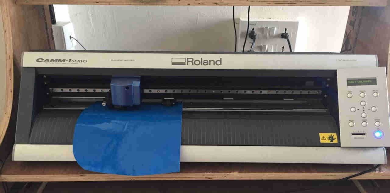
The machine here is Roland CAMM-1 SERVO.
 (Source -Original)
Vinyl cutter is analogous to our normal printer except that the printing tip, which is a sharp cutting pointer. Vinyl, Copper and Epoxy can be printed. The material can be fed to the machine as rolls(just like paper in normal printers). The moving arm of the machine moves on predefined patterns set by the computer. The moving arm holds the sensor and the cutting tool. The cutting pen can be removed and fixed. The speed and force of arm can be calibrated and adjusted for optimum use.
 Source -Original
 Source -http://fab.academany.org/2018/labs/fablabtrivandrum/students/akhil-hari/4week/week4.html#1
Bitmap
I learnt that in computing bitmap is a way of mapping from data in the image to bits, the type of data required for tool path generation. An image may be made of fixed number of pixels. Each pixel can be mapped for its value in terms of colour, saturation, etc. by bits of data. This data can be easily employed to find edges/paths for the CNC machines to create a tool path. This is acheived by various softwares like Inkscsape. Say here I have used the picture of a football. It was imported onto Inkscape and its Bitmap was traced from it.
(Reference: Wikipedia)
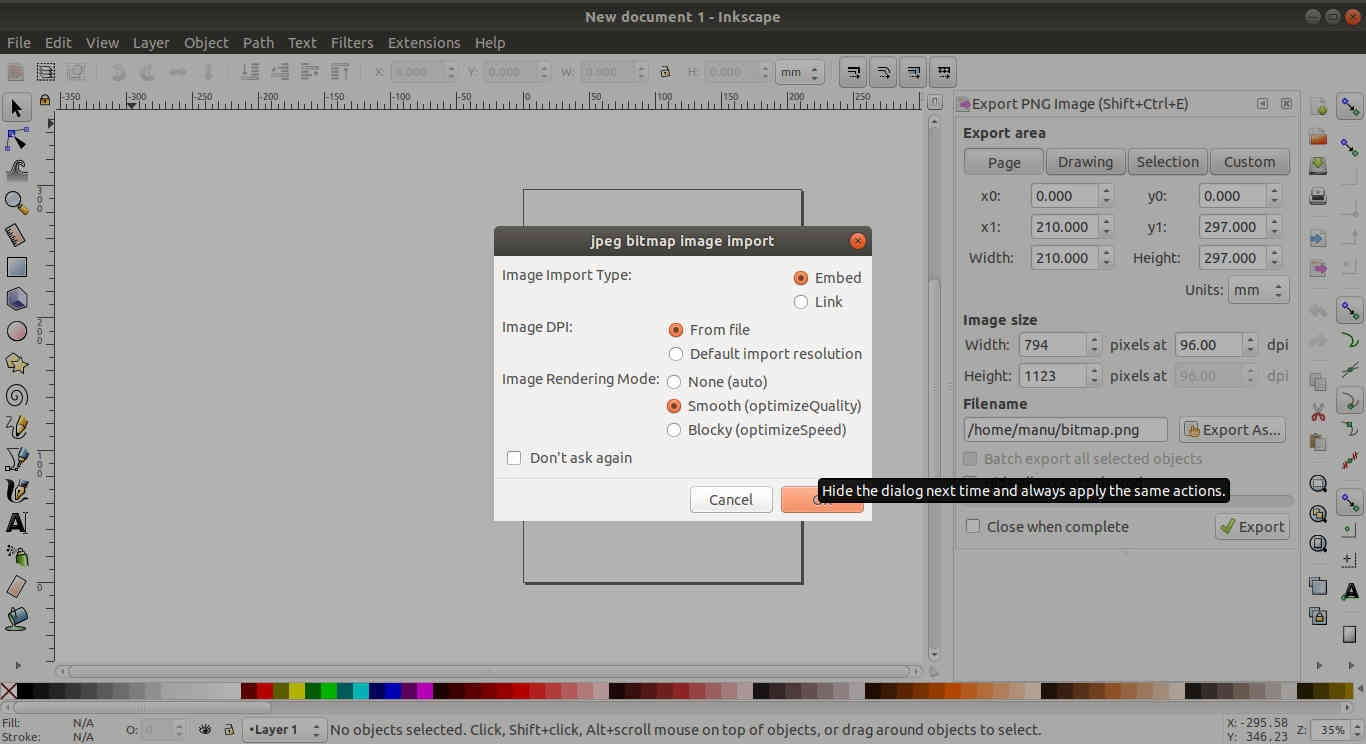 Importing the image using
 Trace Bitmap tool
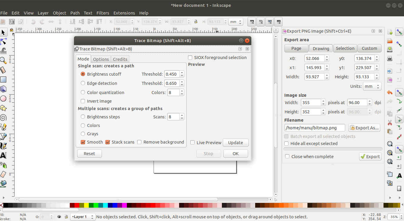 There are various options. Brightness cutoff, where the variation in brightness is found and boundaries demarcating the prescribed cutoff thresholds is chosen as path.
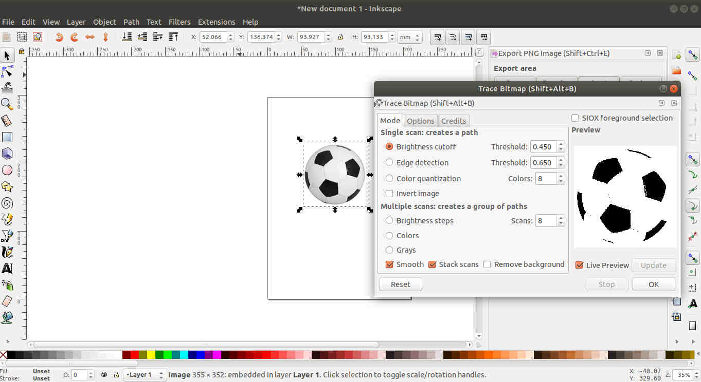 When Brightness cutoff was used
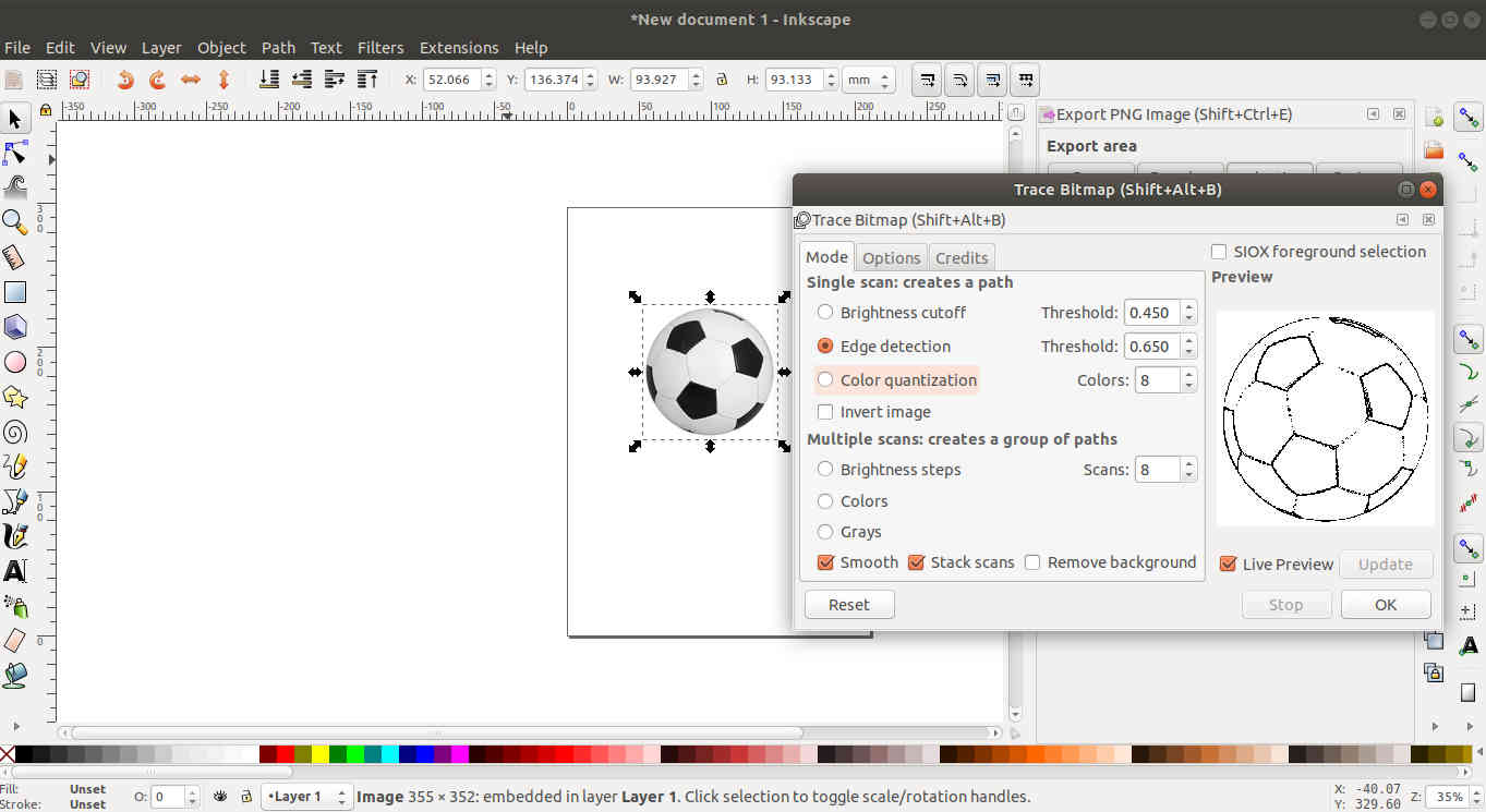 Here we used Edge Detection.The bitmap image is very different from the previous one. But this is not the one we want.
The sequence of my work is here below
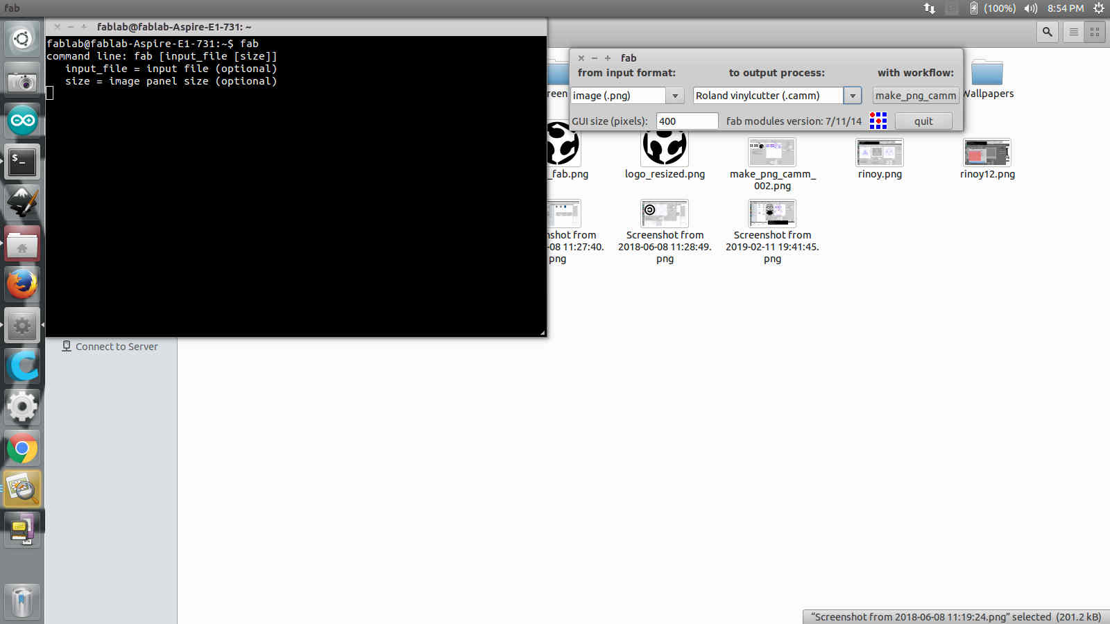
1) Used Inkscape to convert the picture to a bit map image using Trace Bitmap with a suitable scanning procedure. This is essential as the machine can best understand the vectorized format of the picture. Saved the image for 150mmX150mm size in .png format. The image is to be read in .camm format.
Original file
Vector file
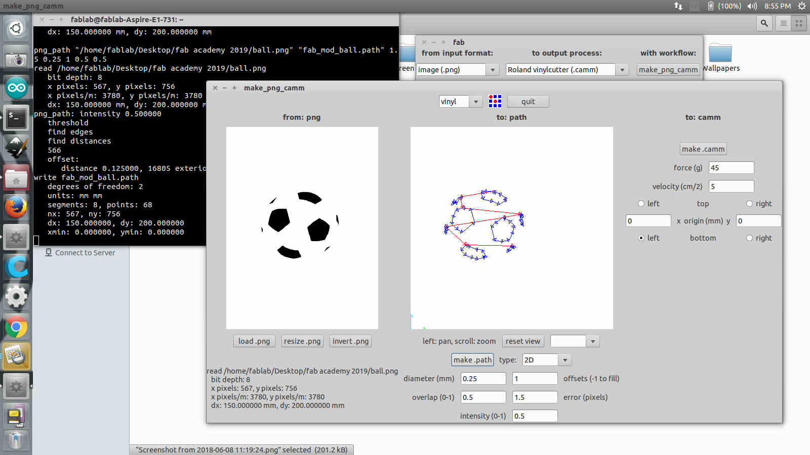
2) Open the machine configuration to load the image. Here I found that the machine has laid a cutting path in blue and red lines over the vector image in the preview window, indicating its passes and path. The efficacy of the cutting depend on the resolution of the image. Clearer the resolution clearer the paths. Also it is here that we specify the dimensions of the output.
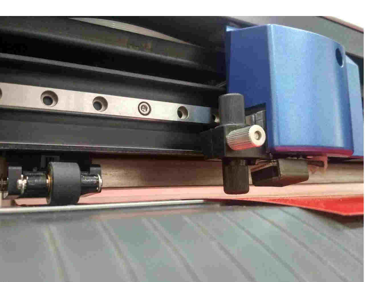
3) Load the roll/ piece of Vinyl and lock it using the latch at the back. The roll/piece type of feed can be changed in the machine. Along side the feed roll there are two rollers that can be adjusted along the length of the machine. These two are to be kept seperated only in the white bands given.
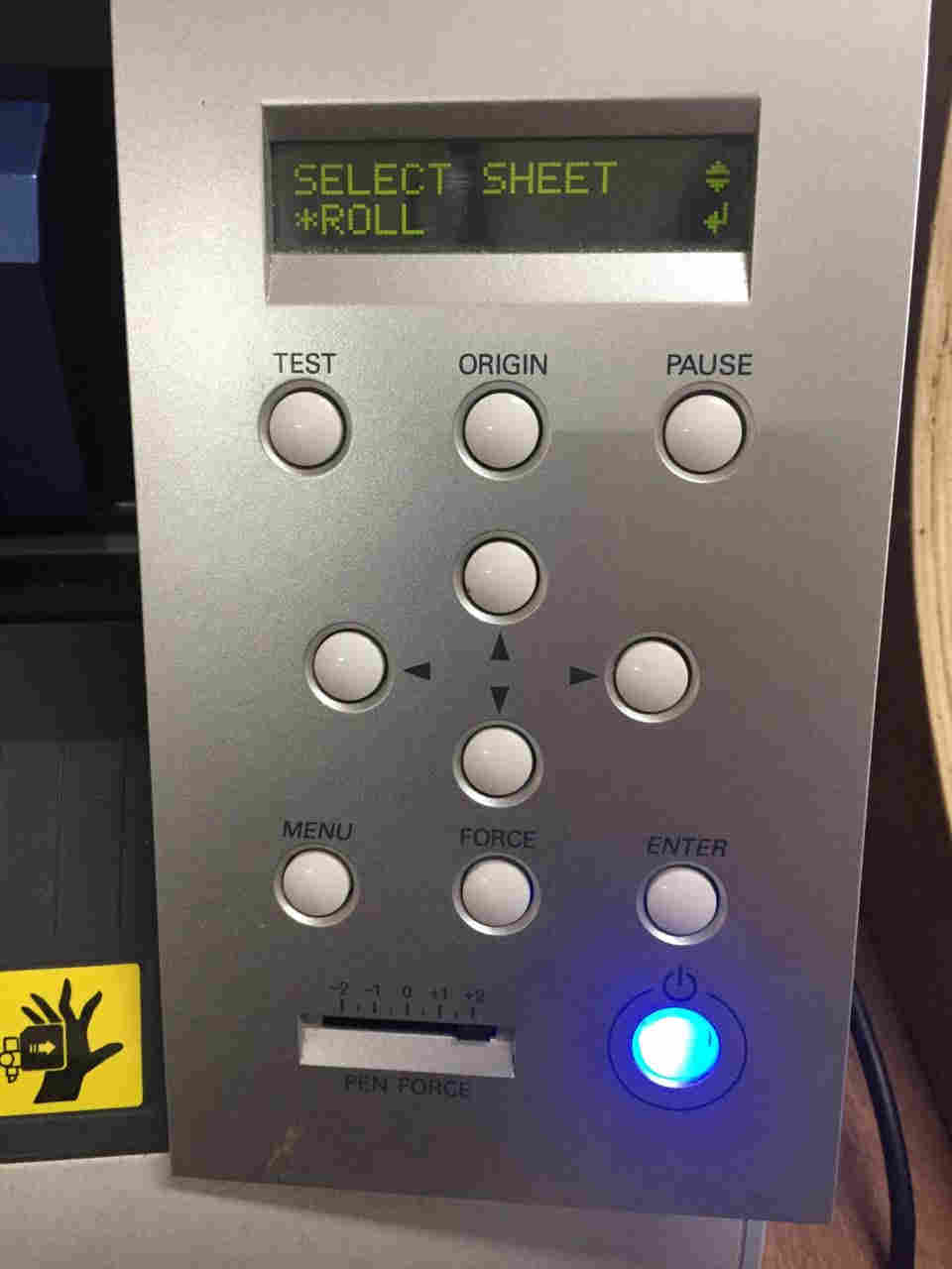
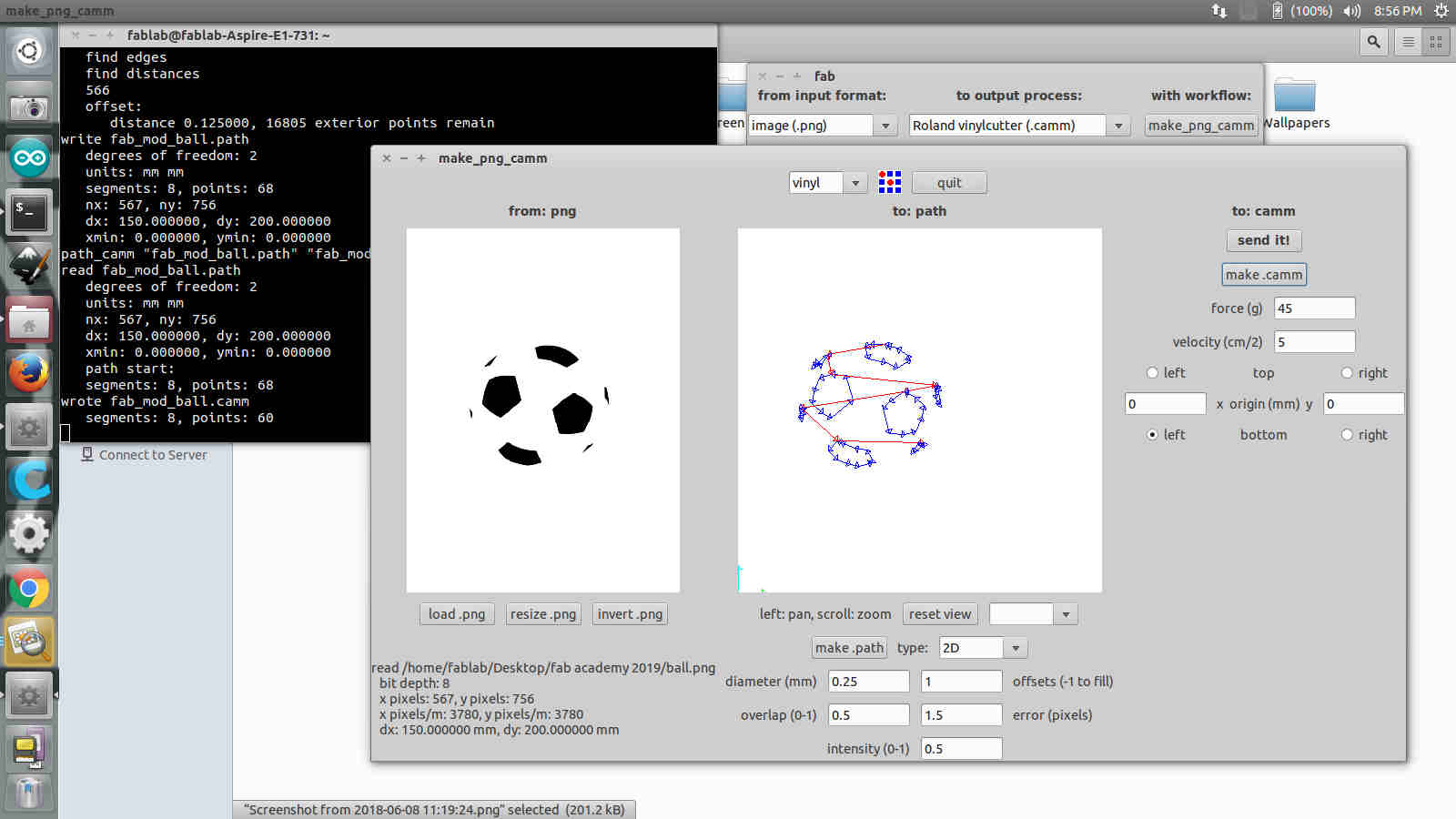
4) Set the origins by pressing the origin button for 2 seconds. The sensor can be sublty adjusted by the arrow keys. Once set we can send the image from the computer for printing by Send it.
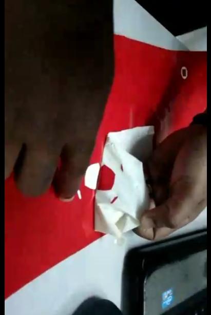
5) Weeding out the unwanted part was the most exciting part. Carefully the masking tape is pasted over the printed vinyl and slowly sheared rather than pulling out perpendicularly and applied on my laptop.
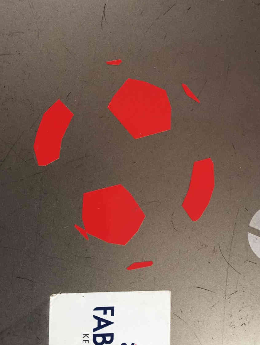 The Heroshot !
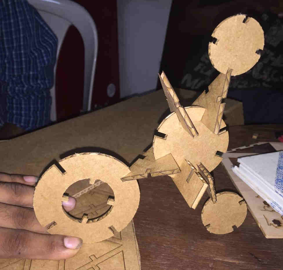
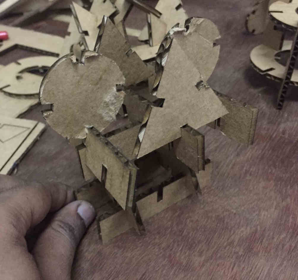
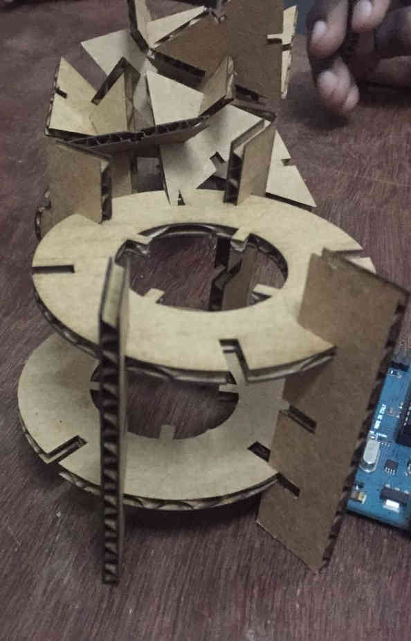
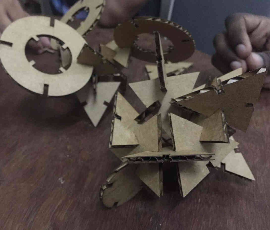
Press and Fit Construction assembly
This week the individual assignment was making a construction press fit assembly (like Lego) . The components are to be cut from a thick quality cardboard. For that our patterns/blocks are to be prametrically modelled and fed tot the machine. Parameters could be anything from thickness of the material to the kerf. Here we define the dimensions of our design as functions of basic parameters. These basic parameters can be created and edited. Once the designs are ready they can be cut using the LASER cutter. The advantage of parametric modelling is that once designed, we can change the dimensions in the design without reworking the entire model using newer changed parameters.
What is Kerf ?
Whenever laser cuts through the material, it burns away some material. The thickness of lost product in a single cut is called Kerf. This comes important when we design slots and tabs. As slots will be more wider and tabs will be shorter than our design if the kerf is not accounted for. The kerf is specific to the laser machine, type of material etc.. Our group assignment was standardizing kerf for various materials.
As the LASER machine in our lab is down we were told to prepare the designs and be ready for this week.
Parametric 3D modelling
Autodesk Fusion 360 was used to model the basic shapes in the construction kit. A grooved circle, triangle and a rectangle was designed parametrically. The basic dimensions of these shapes were kept functions of thickness and kerf. Fusion 360 allows us to construct shapes in sketch module. There are various constraint tools like coincident, colinear, perppendicular etc.. that can be used to generate basic shapes. Parameters can be defined from the Modify tab.
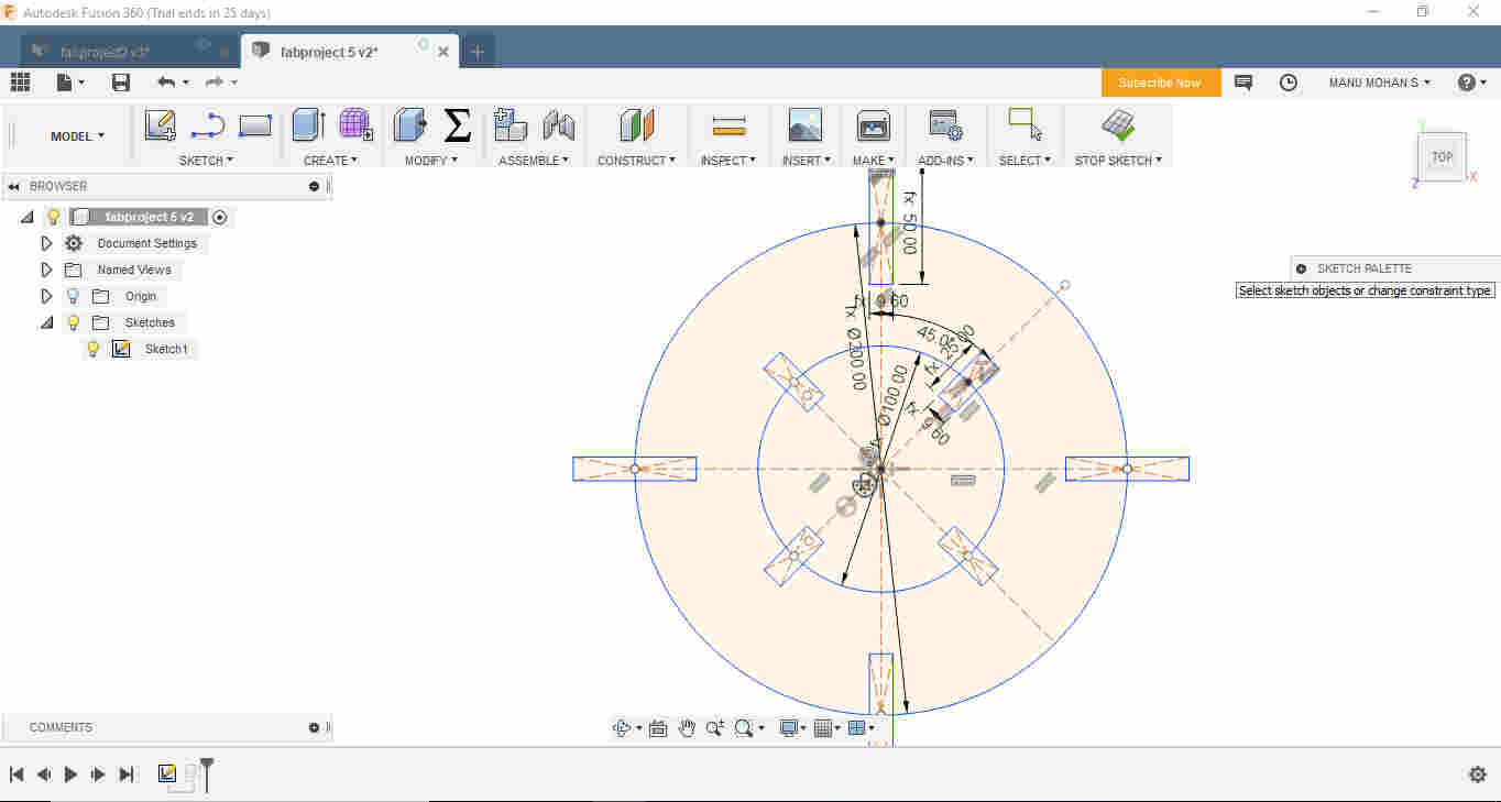 Creating circle in the Sketch Part
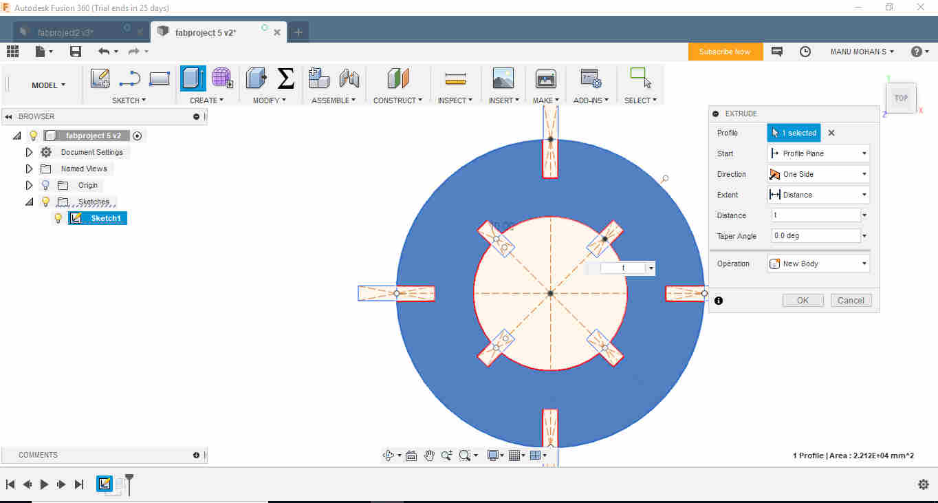 Using
Using Extrude to develop the thickness
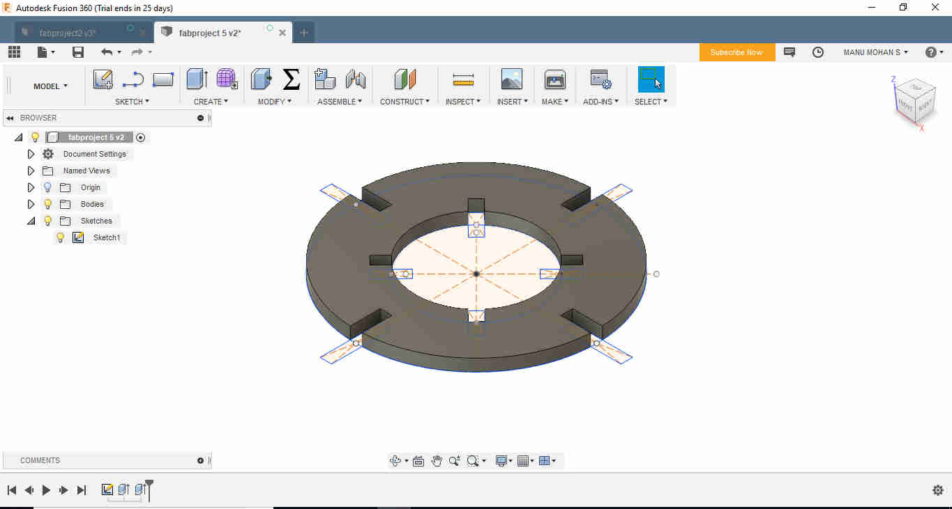 Slotted Circle
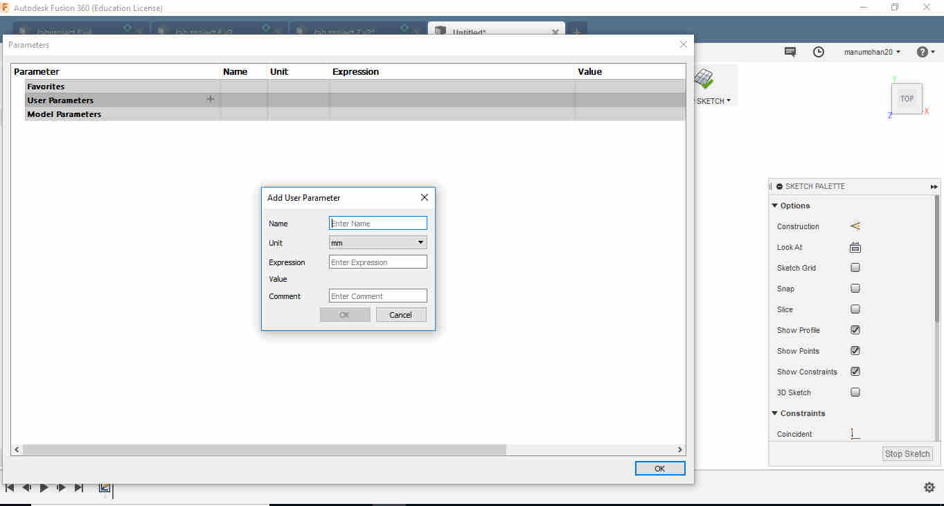
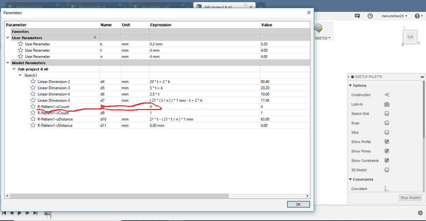
Parameters defining. Here slot width was taken as (thickness-2xkerf)
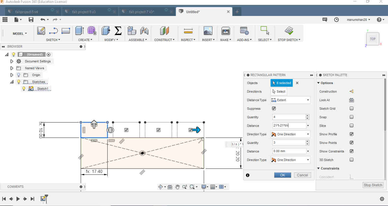
 I had used n a parameter to fix the number of tabs. However for process of replicating the rectangle tabs a command as
 Rectanglar Patternwas used in Sketch. The number of repetitions could not be given parametrically. Need to find a way around it.
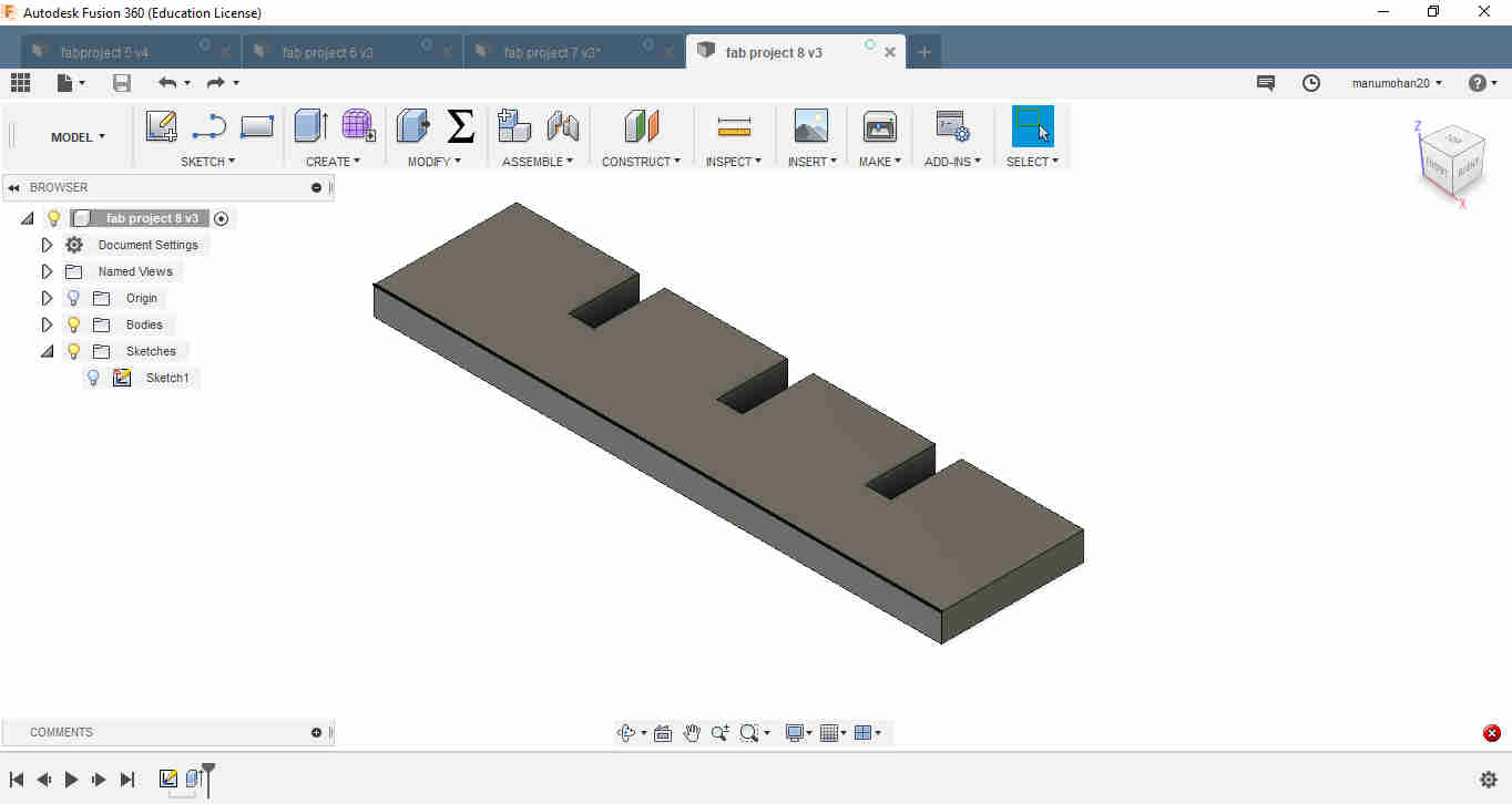 Slotted bar
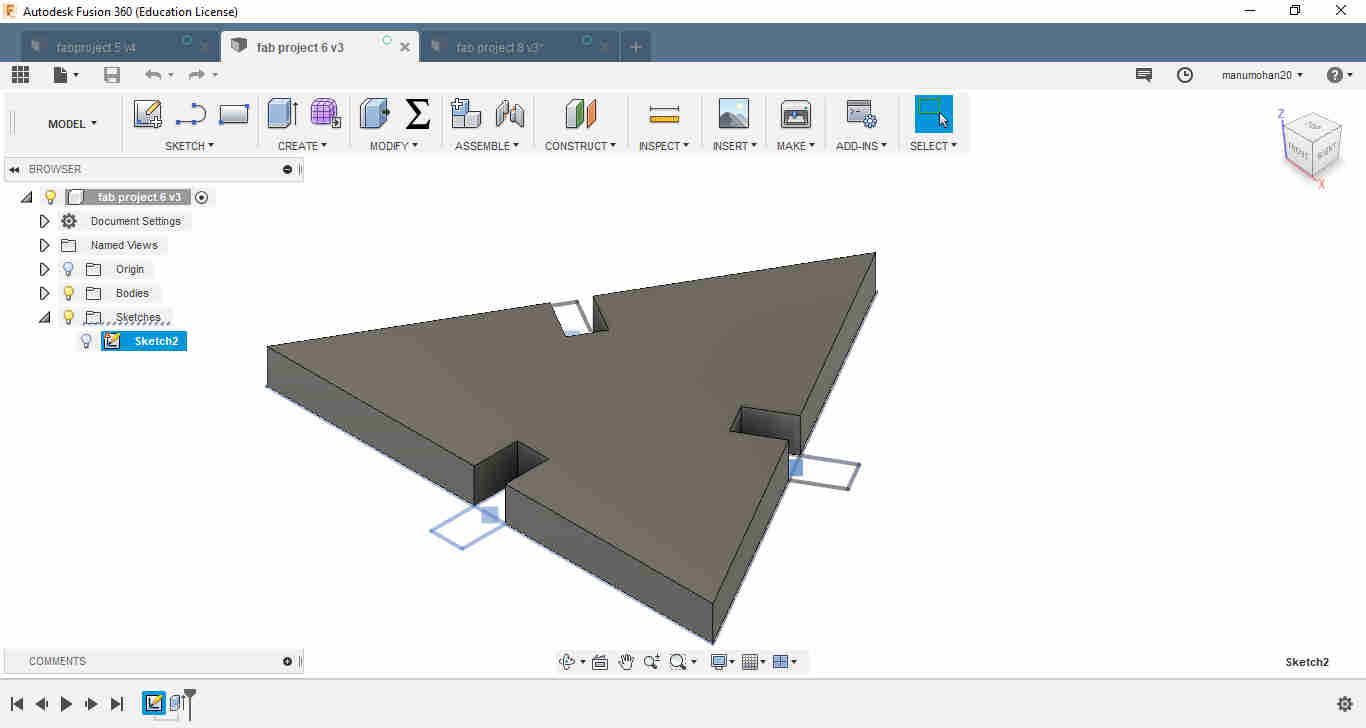 Slotted triangle
LASER Milling
The machine that we have in our lab is Trotec. However the machine isn’t working. An alternate arrangement was made to use Epilog Mini 24. It has a bed size of 24”x12”. LASER uses highly powered and foccused LASER beam to cut materials like Acrylic, Plywood(1/8” t0 1/4 “) etc.
Characterisation of Epilog Mini 24
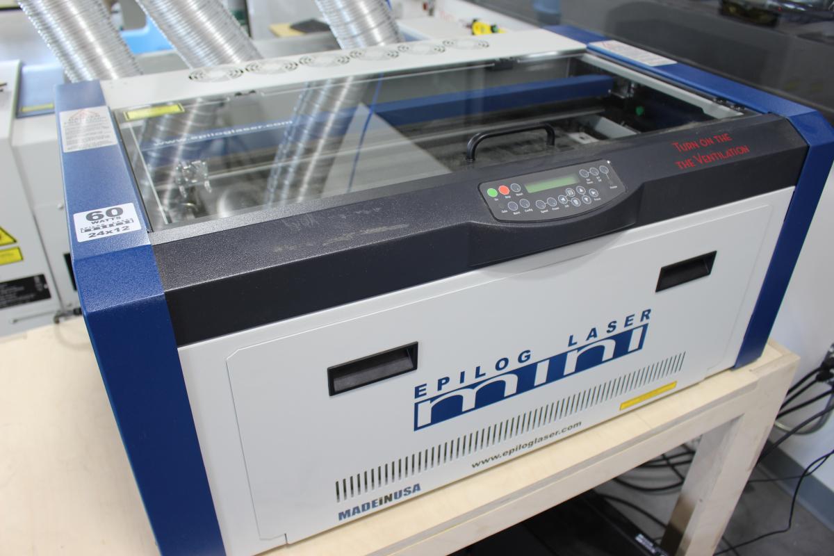 Source:https://innovationstudio.unl.edu/epilog-mini-24-laser-cutter
The various characteristics of a LASER cutter are Speed,Power and Frequency. This varies for different jobs and material. Job can be either cutting or engraving. Inorder to understand the behavior of the machine test cuts were made in 3 different materials available at lab. For guidance the settings was referred from the manufacturer’s catalogue.
Manufacturer’s Catalogue here
To find kerf test cuts for 50x50mm squares were cut out from various materials like thin veneer craft plywood,cardboard and 3mm acrylic. After cuting the sides were measured to find the loss of material in one side. Sides were found to be less than 50mm. The difference in lengths will give 2*kerf for both the cuts on both sides.
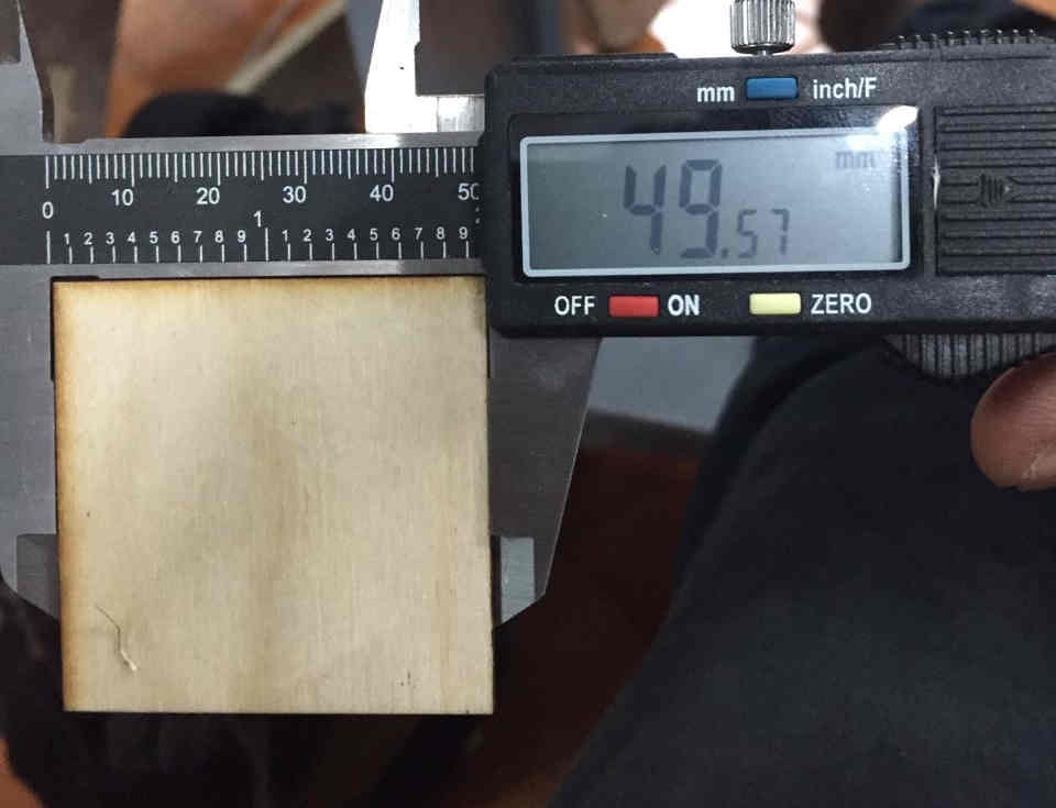
It yielded the following results
3mm Acrylic : approx .15mm
3mm craft plywood:.12mm
4mm cardboard:.15mm
The next process was to find the optimum fit for press and fit assembly. For that a comb shaped structure with slots for fitting different sized pieces are made.
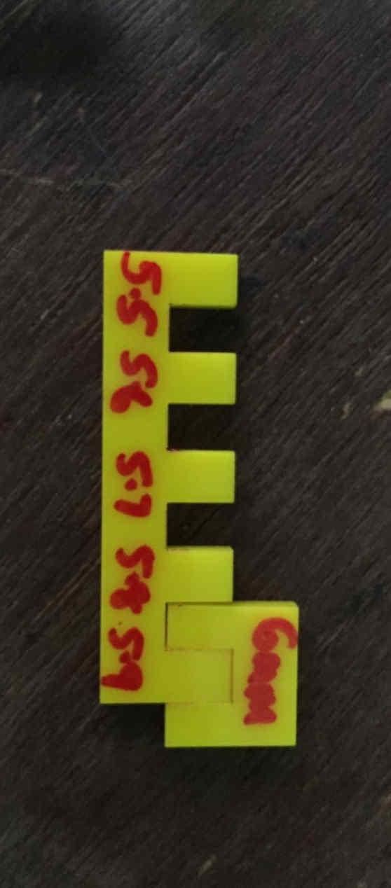
Acrylic tabs for different sizes were checked for slot with 6mm. These slots ans tabs are designed after accounting for the kerf in the parametric equation of the design. It was found that 6mm would fit tightly for a tab of 5.9mm, which means that 0.1mm is the allowance for pressfit in acrylic in this machine.
Ventilation and Air assist
It is very important that the fumes generated during cutting are to be sucked out and filtered out. Also built up burn debris may reduce the accuracy of the lens. Airassist of the Trotec machine works using air compressor and a filter. The output of the pummp is fed outside.
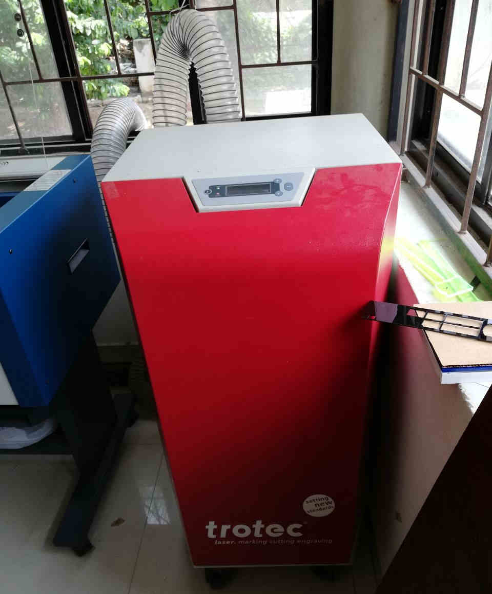 Airassist
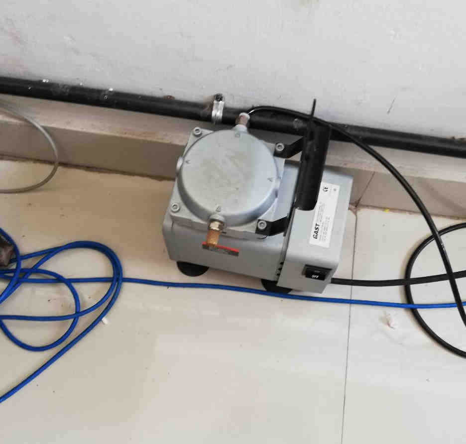 Airpump
Working
The LASER has a source and it is reflected by the lens in the LASER head orthogonally like a prism and focussed on to a small area for cutting operation.
Like any other CNC machine this machine’s zero has to be set. The machine’s bed can be lowered or raised using the conveyor belt/keys. The attachment as shown below is kept on the laser head and bed is raised such that it touches the surface of the cutting material. This way the Z axis is set.
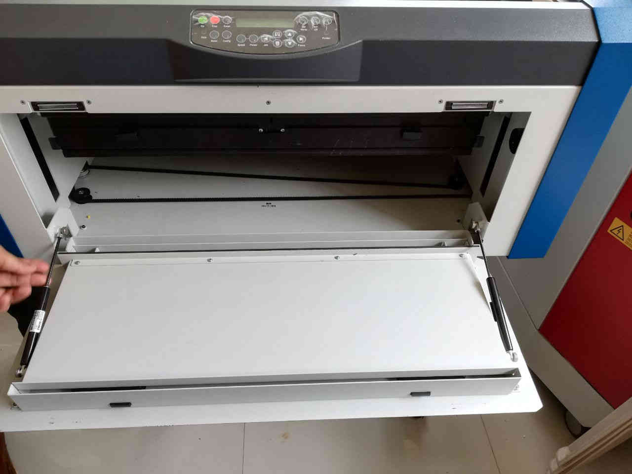 Adjusting the bed by pulling the conveyor belt
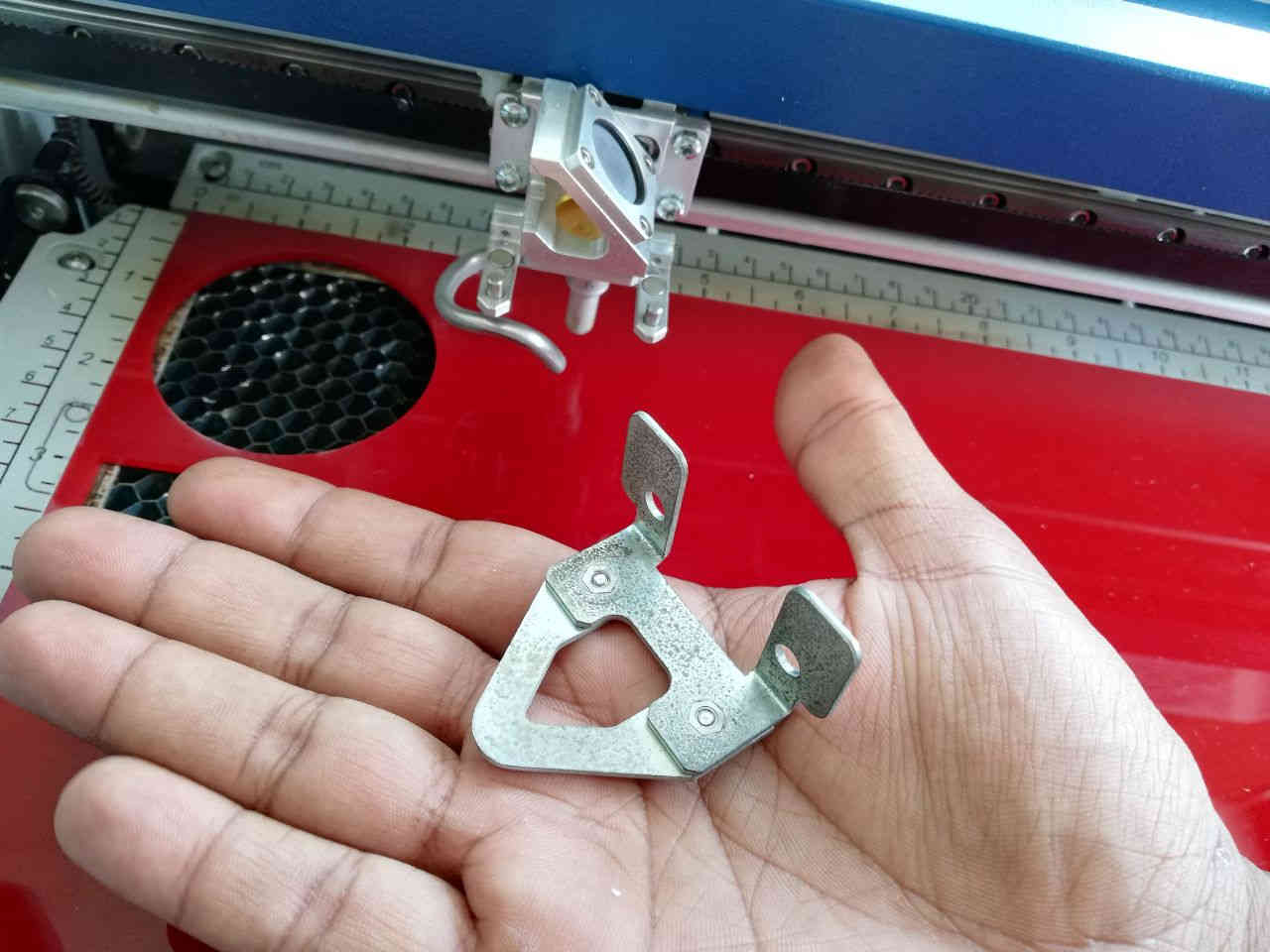 This clamp is attached to the laser head for zero setting
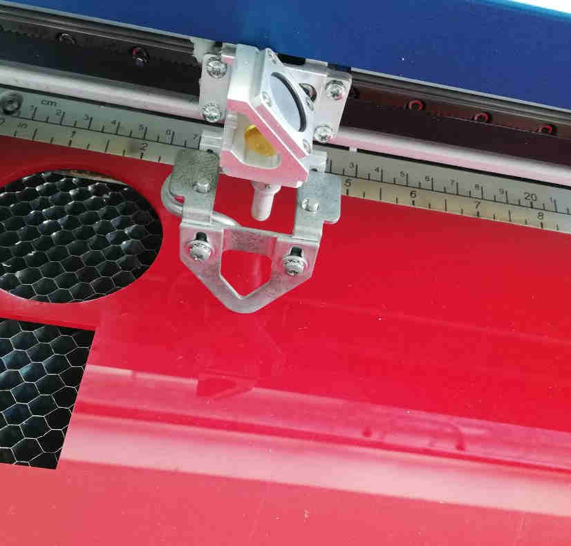 Clamp in the LASER head
After settting the Z axis, the X and Y axes are to be set to zero manually using control panel.
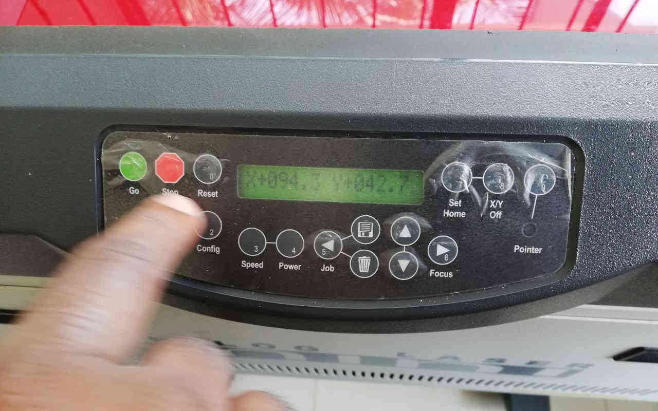
Once the file is sent for printing from the computer, it will be shown in the control panel display. The X and Y axis is set using X/Y Off button and manual moving the laser head.
Sending the file for Printing
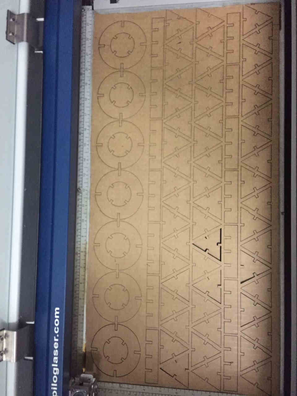
The design files are exported as .dxf and are sent to Rhinocerous for cutting.The shapes are stacked closely to avoid wastage of space.
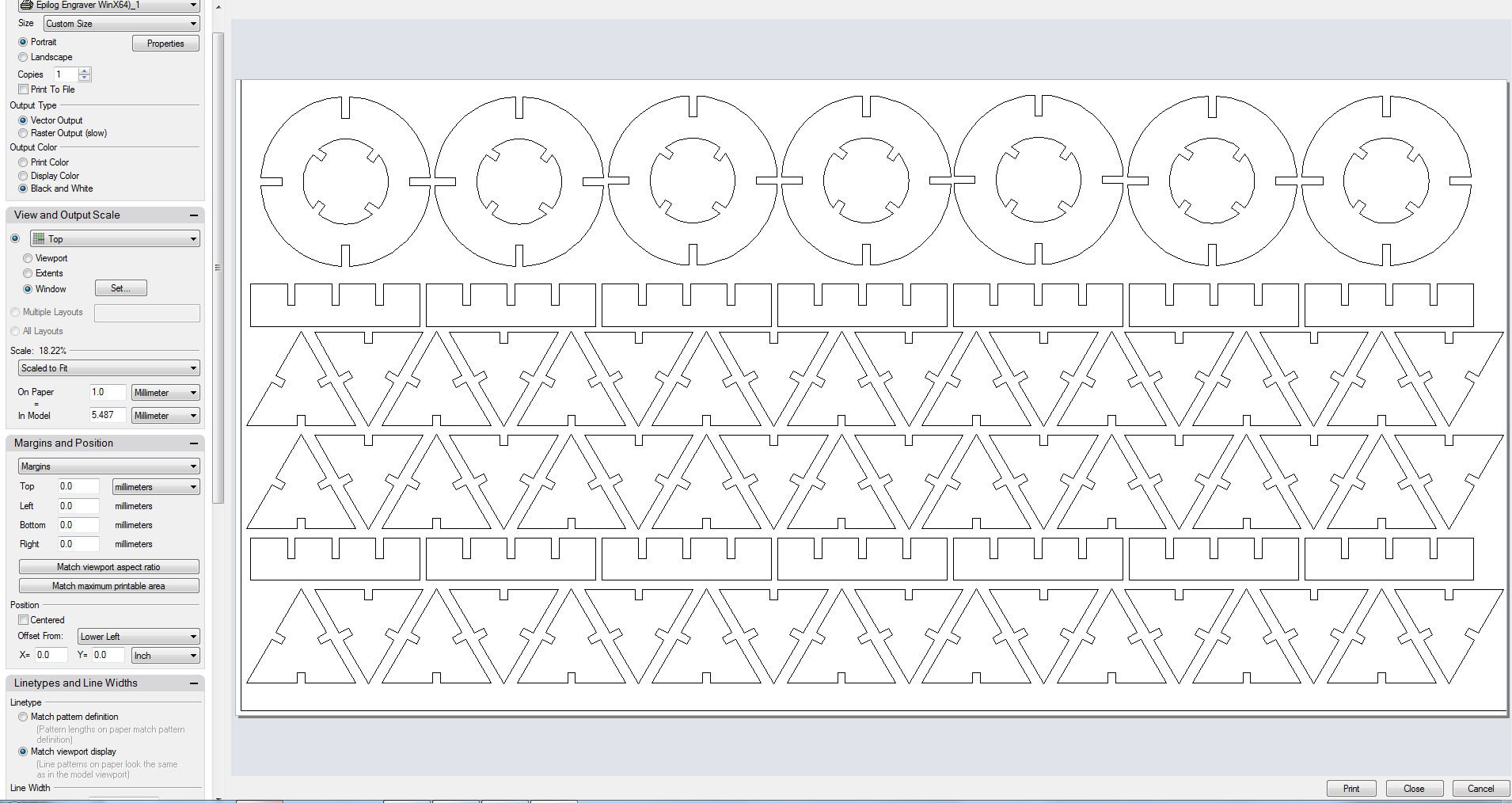 Rhino interface, the Eplilog Mini is interfaced using a printer driver plugin. It is ensured that the scale is set to 1:1.
The cutting settings are adjusted in the properties.
Rhino interface, the Eplilog Mini is interfaced using a printer driver plugin. It is ensured that the scale is set to 1:1.
The cutting settings are adjusted in the properties.
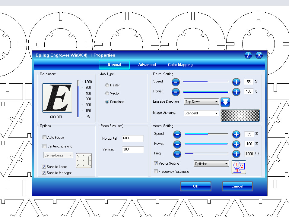 The settings are selected from the manufacturer’s catalogue above and they vary for job and material.
Laser DXF file
Working Video
References
1)Kerf