6. 3D Scanning and printing
3D Printing
Introduction
This week we learnt the basics of 3D printing. 3 dimensional printing is nothing but an additive manufacturing process whereby material is fused and deposited layer by layer by a moving extruder head based on inputs received from the CAD model.This soldifies to give the desired shape of the material. Chuck Hall in 1983 invented this technology while working on photopolymers, a special material which on exposure to ultra violet light can fuse and solidify.
Different type of 3D printing based on the technology are
- Vat Photopolymerisation/Stereolithography
- Material Jetting
- Binder Jetting
- Powder bed fusion
- Material extrusion
- Directed energy deposition
- Sheet Lamination
Materials
The various materials used for 3D printing are
1. ABS (Acrylontrile Butadiene Styrene )
2. PLA (Polyactic Acid)
3. Polycarbonate
4. High density Poly ethylene (HDPE)
5. HIPS (High Impact Polystyrene)
6. PETG (Polyethylene Terephthalate)
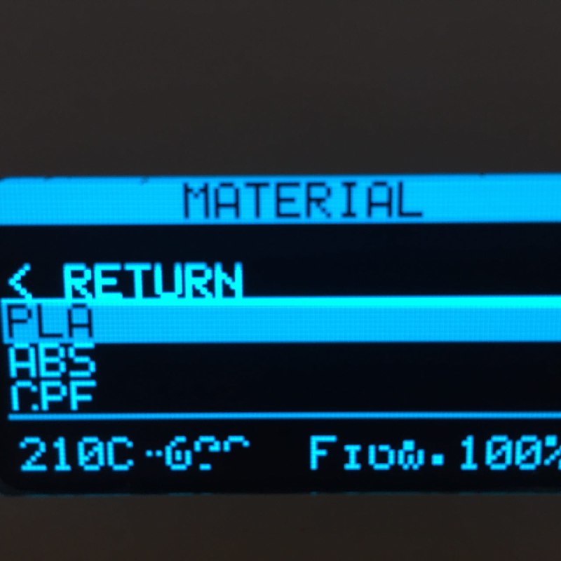
Here in the lab we used PLA for prototype printing. These come in spools
The most commonly used is Fused Depostion Modelling (FDM). Fused material to be printed is forced through an extruder to make the 3d shape layer by layer. The extruder head will be controlled by the machine whose motion is controlled by an input G code file of the respective CAD file. Usually the platform of the machine move in Z direction to build the layers. Thickness of the layer can be adjusted.If the layers are made thinner a better resolution of the printed object can be acheived. Similarly the fill of the material can also be changed Depending on the geometry of the model, support structures are also printed for supporting overhangs etc. These supports are later removed.
The following process are involved in 3d Printing
1. Designing the model
2. Slicing or Converting the 3d CAD model to machine readable language(G Code)
3. Printing
Our lab has two machines both work of FDM process.
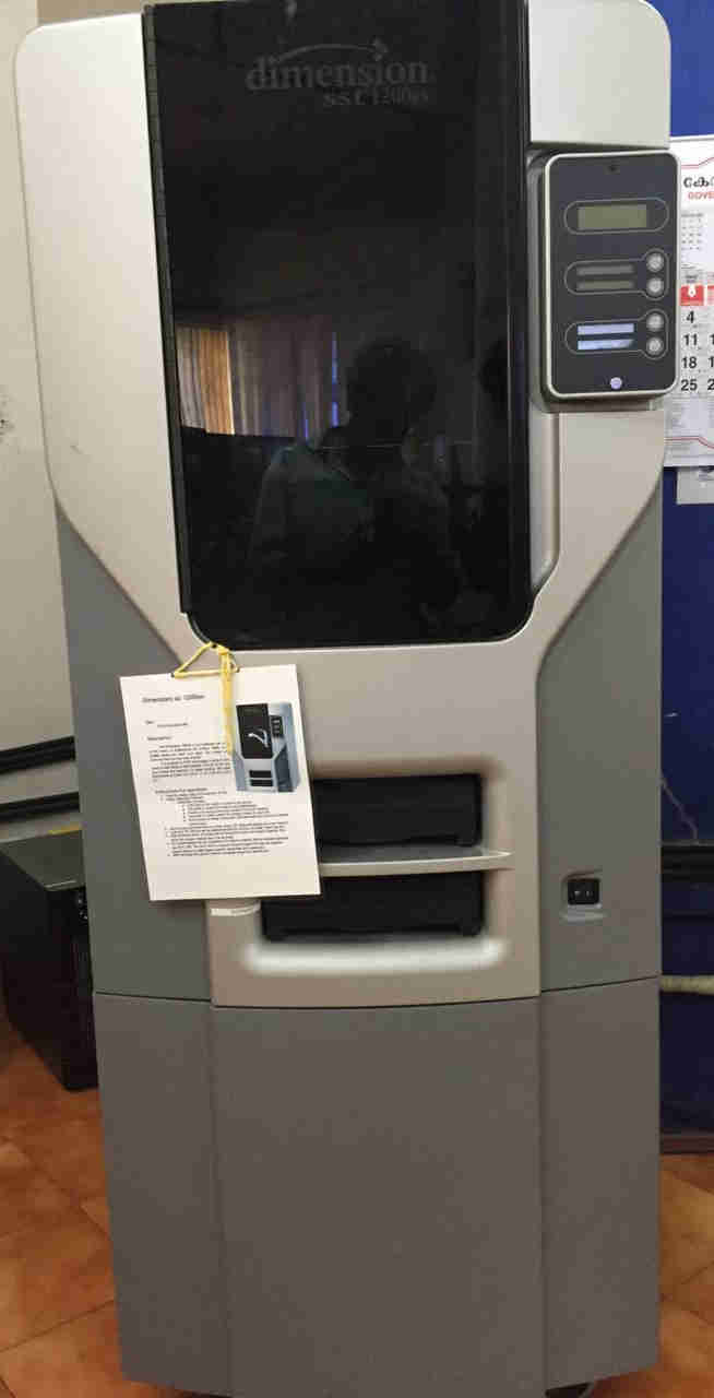 Dimension sst 1200es. In this machine the only print material that can be used is ABS.
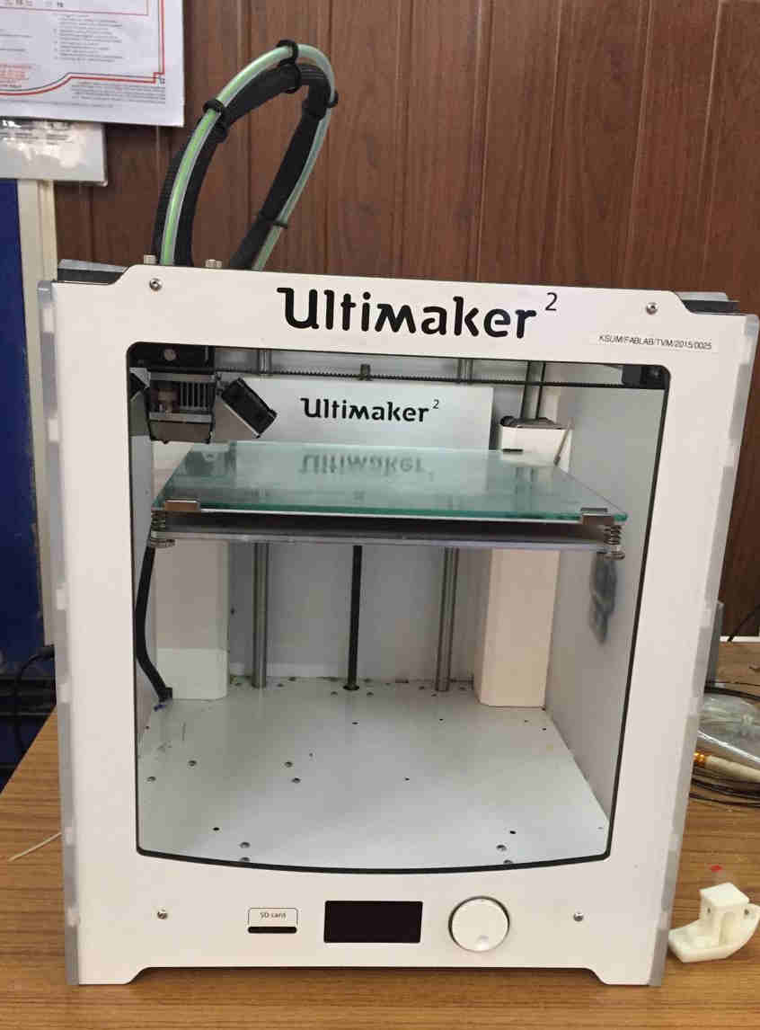 Ultimaker 2 (The extruder head can be seen at the top left part)
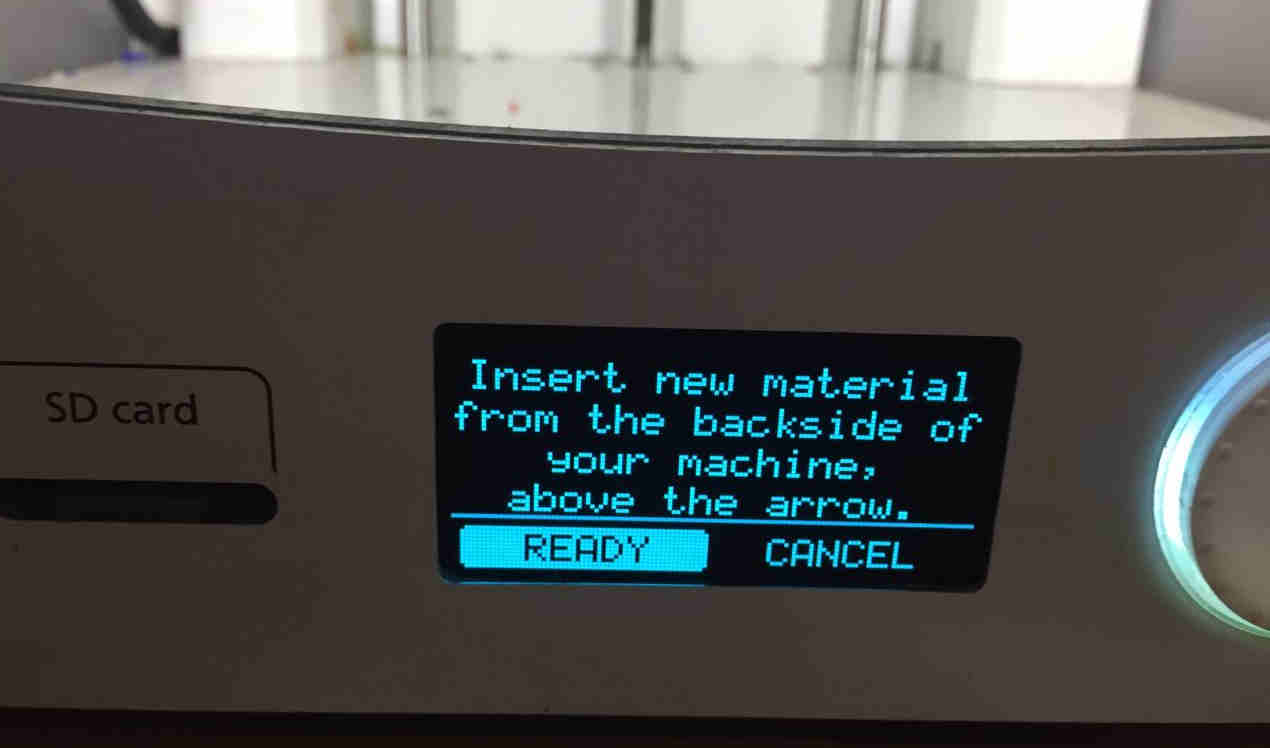
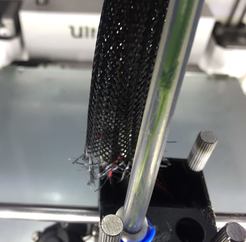
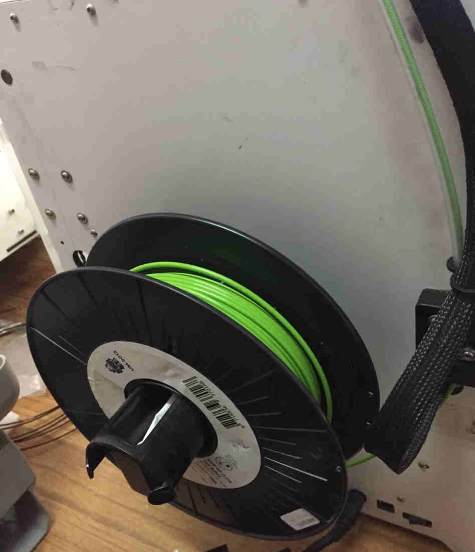 PLA Spool is mounted at the back of the Ultimaker 2. Beside the spool we we can see the filament passing through the conduits to the extruder head.
Assignment 1- Design rules for Ultimaker 2
Aim
In this assignment we fixed the design rules/calibarations for Ultimaker 2.
Ultimaker 2
The nozzle diameter for Ultimaker 2 is .4mm. The printer head/ extruder is heated and kept at 210 degree celsius so that PLA is plastic and can be extruder as fine threads. The design G code file is given as external memory card in the slot in the front part of the machine. The build volume is 223x223x205 mm. Ultimaker has an interface to select the functions like selection of print material, showing the status of the nozzle, its temparture, time left to complete the job etc.
Design Parameters
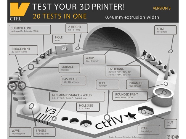
For testing the design file was downloaded from Thingiverse an opensource online 3d printing community.
The design files were downloaded from https://www.thingiverse.com/thing:1363023
- Quality -It determines the smoothness/resolution of the print. Smaller the layer thickness more smooth and homogenous would the print be. Here we set .15mm as the layer thickness
- Thickness of shell. In cases of printing shell like structures, these come into importance. Here we used .8mm as thickness of the shell.
- Infill density and pattern. Infill density was chose to 20 percent and grid pattern was chosen.
- Material properties- Whether to enable retraction
- Print Speed - Speed of printing of infill inner and outer wall, accleration of the printer head etc. It was set as 60mm/s.
- Cooling of the fan in the print head configurations.
- Support details- Supports are to be given /automatically designed by the slicing software for printing overhang parts. We change the parameters like support density, overhange angle etc. Here automatic support generation was turned off.
- Build plate adhesion
The software called Ultimaker Cura was used for the slicing purpose. Slicing process necessarily converts the CAD design to machine G code on layer basis.
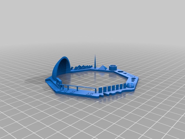 Model view rendered
 The model dimensions
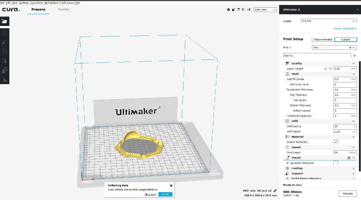 Cura Interface-adjusting the print Parameters
Finished print
Issues during Printing
Breakage of PLA feed material in the conduit.
 The printing process was paused and the material was extruded out manually turning the knob and snapping some of the PLA material. The extruder head was cleaned off of the excess PLA.
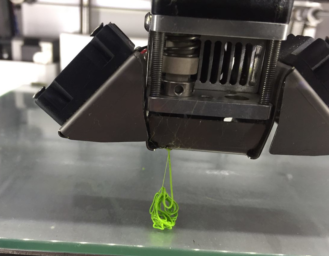 Excess PLA cleaning out of the nozzle
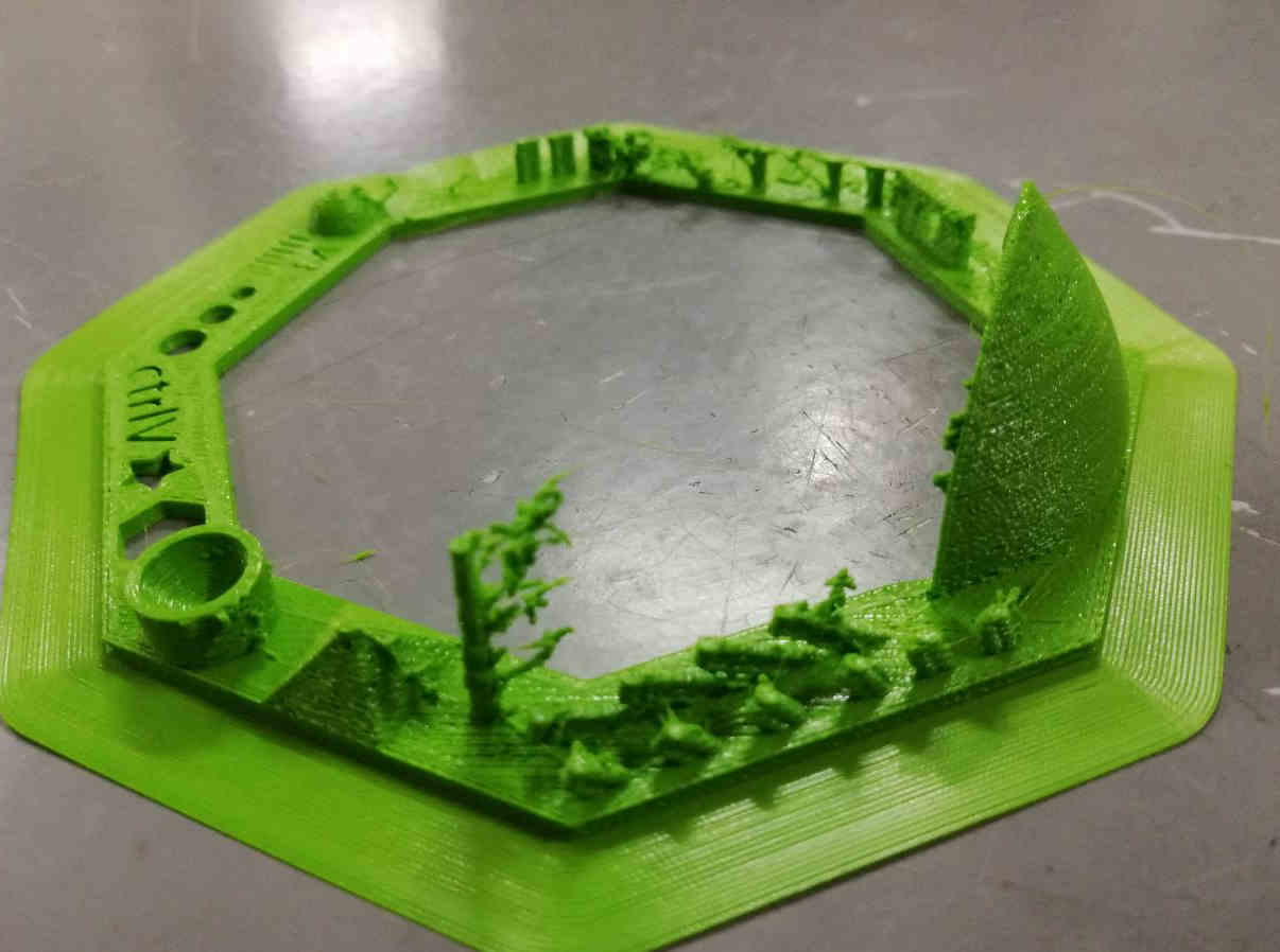
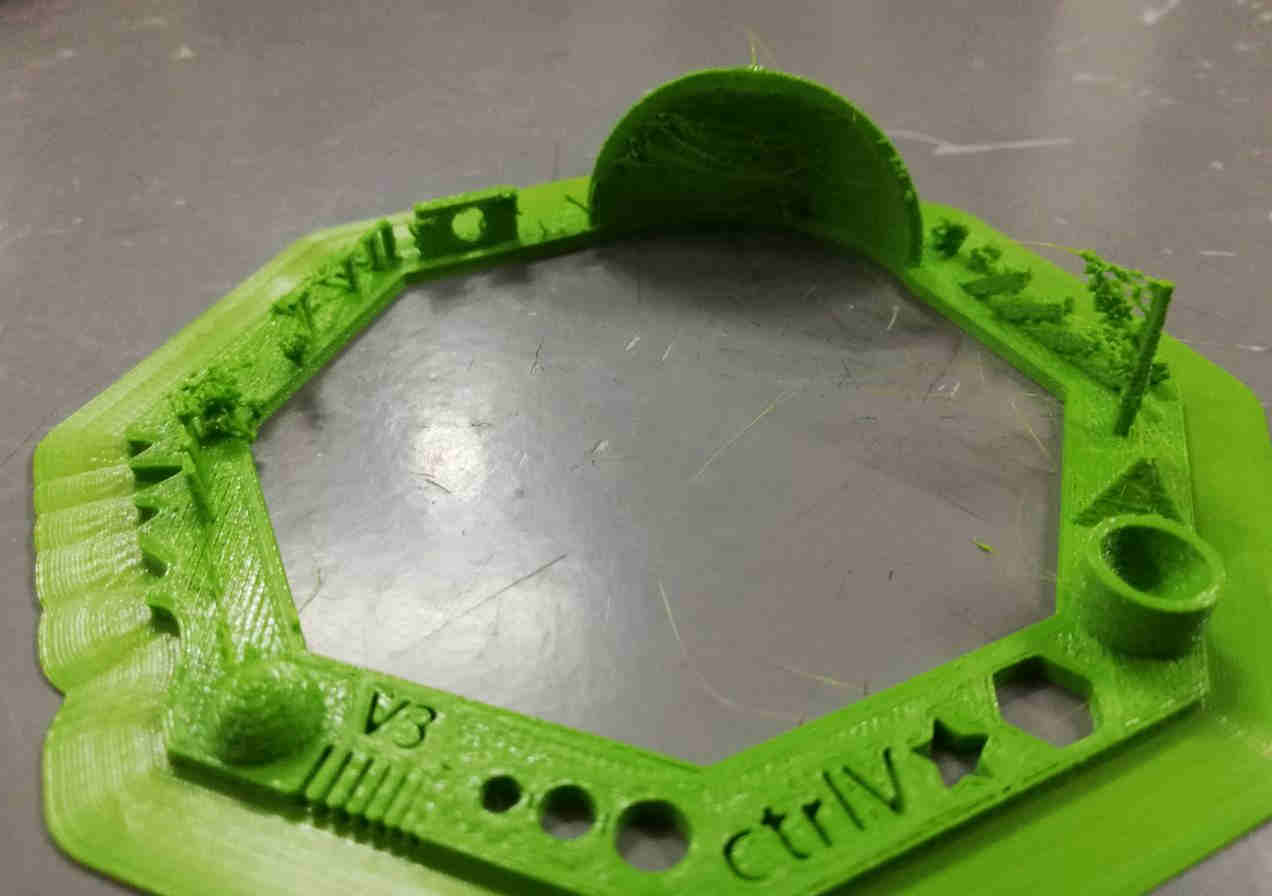
Issues with the finished print
- The warping formed was well but with traces of support material.
- The bridge part has ruptured.
- Overhang of 25,30,40,45,50,55,60,65,70 degrees were printed without support, with excess material on the surface.
- Rounded print was achieved around the wave.
- Spike was incomplete and got ruptured with excess PLA.
- Gap distance between walls were closed for width less than .3mm.
Assignment 2- Design and 3D print
Our aim was to design and something that cannot be made subtractively. A simple mechanical hinge was designed in Autodesk Fusion 360.
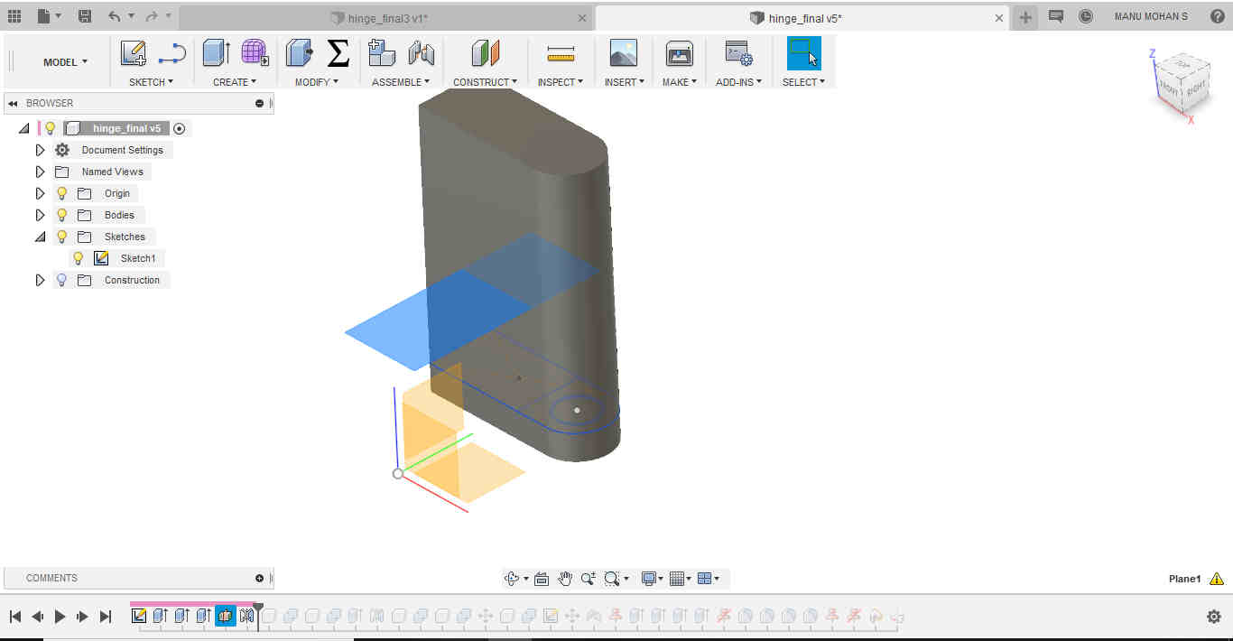
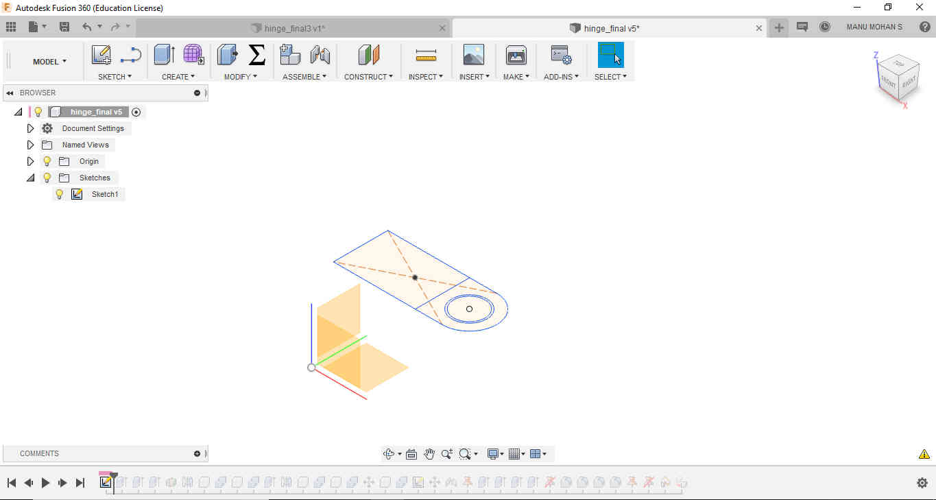 Made a sketch
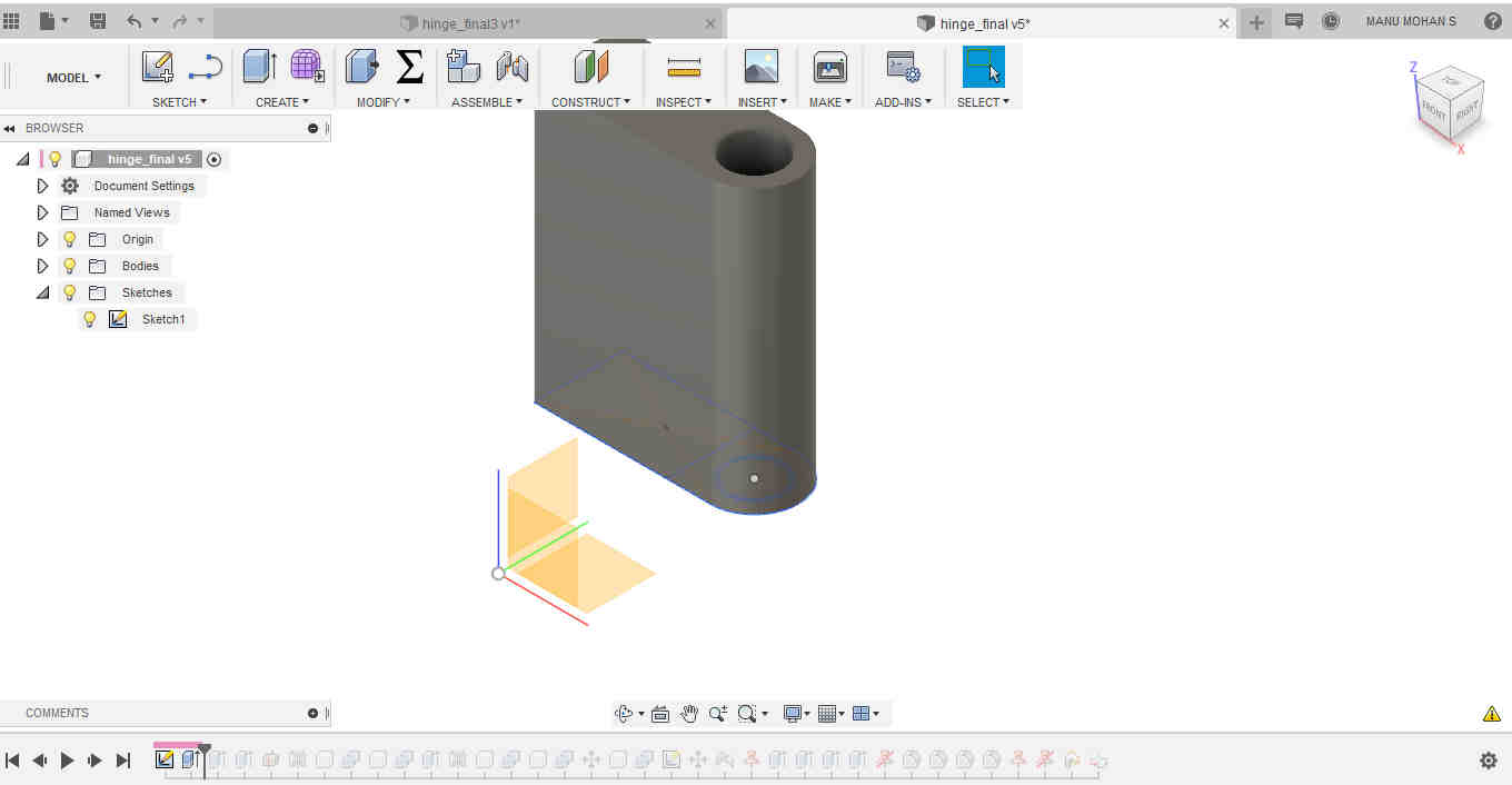 Extrude
 Extruded downward to have a closing part at the end
 Extruded a cylinder inside the hole seperately. This is useful to be combined with the other part of the hinge.
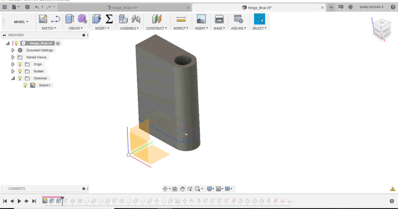
 Used mirror to add the symmetrical closing part at the end to the top side
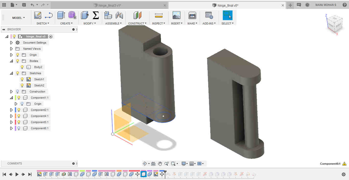 Used Move tool to copy the other part of the hinge. The shaft was combined to this new part using Combine tool.
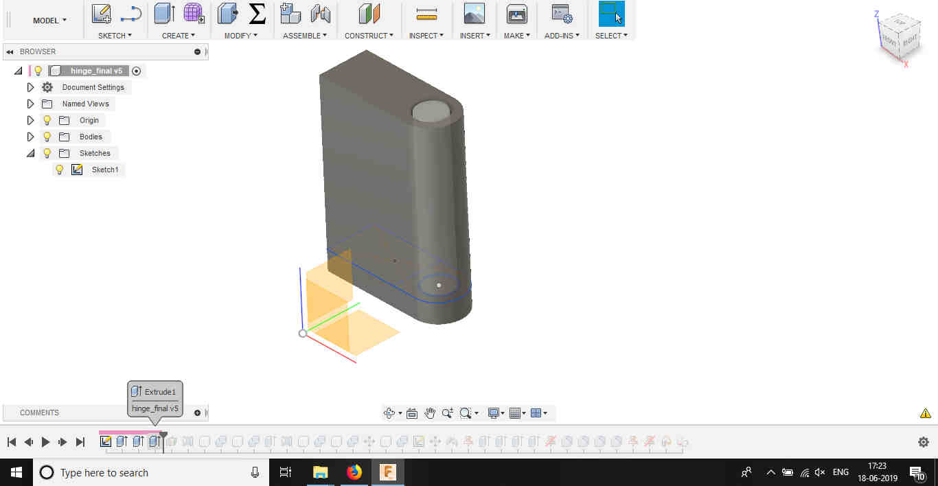
 Used Fillet to round the sides
Allowances were kept for the turning part(.8mm). The two components were made as components seperately and then assembled.
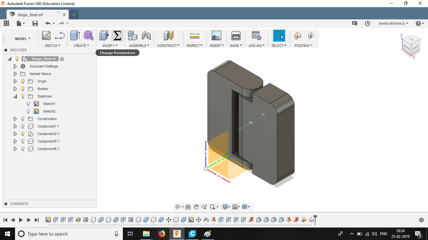
The two parts are joined using Joint tool and selecting rotating as freedom.
The design was exported to stl format and opened in Ultimaker Cura. The animation of the layer by layer building is shown by a slider in the right side of the drawing. The print parameters can be changed in the right side.
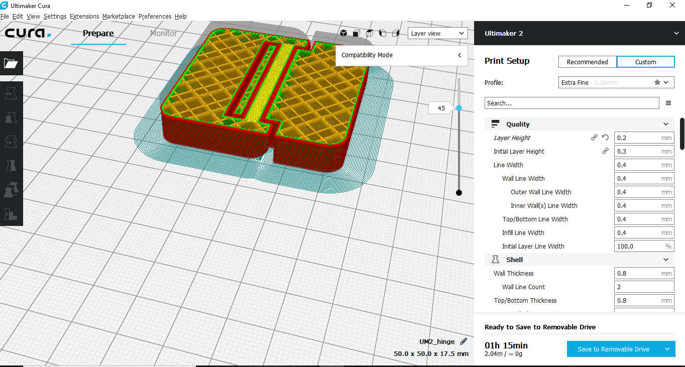
The parameters for printing were
- Layer height -.2mm
- Support density- 4 percent
- Infill density- 20 percentage
- Wall thickness -.8mm
- Infill pattern- grid
- Print speed - 60mm/s
- Retraction- Enabled
- Support pattern- Zigzag
Files here
The files are uploaded in Thingiverse
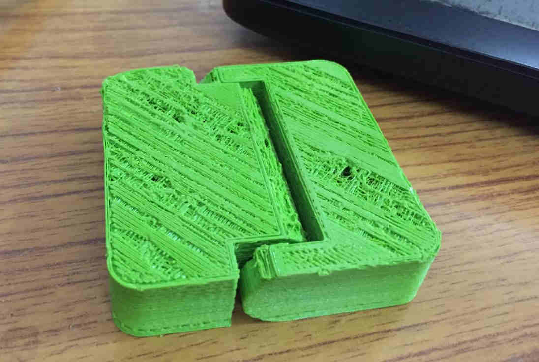 The print
We can see that the surface is not smooth. I think the non uniform heating of the PLA must have caused this. Also I could have set the layer height to minimum to ensure the smoothness of the layer. !
Hinge Working-Video 
3D Scanning
Here we used Microsoft Kinect sensor to scan 3D objects. It consists of an infrared sensor, a RGB VGA video camera which finds the distance from the sensor to the 3D point in the surface of the 3D material.Photos are taken serially by rotating the 3d object. The camera detects the red, green, and blue color components as well as body-type and facial features. It has a pixel resolution of 640x480 and a frame rate of 30 fps. This helps in facial recognition and body recognition. The depth sensor contains a monochrome CMOS sensor and infrared projector that help create the 3D imagery throughout the room. It also measures the distance of each point of the player’s body by transmitting invisible near-infrared light and measuring its “time of flight” after it reflects off the objects. Here we tried to scan ourselves. 3D surface of the object is generated from these photos. Kscan 3D is used to scan the 3D object. Finally the scanned images are combined in the software to prepared and exported as stl.
At a high level, there are two methods you can use in order to capture scans: the single scan method and the batch scanning method. Both methods feature a number of adjustable parameters to suit your preferred way of scanning an object.
The Single Scan Method
The single scan method allows you to capture scans one at a time. This method allows you to take as much time as you need to reposition the sensor and/or scanning object.
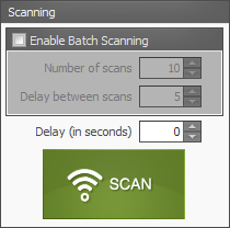
Courtesy: kscan 3d Wiki page
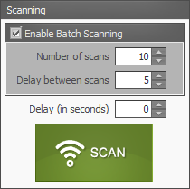
The Batch Scanning Method
The batch scanning method allows you to capture multiple scans.KScan3D will begin capturing scans one at a time, pausing between each scan according to the specified time delay, until the total number of specified scans have been captured.
Here batch scanning method has been adopted.
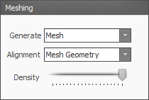
The settings in the Meshing and Point Cloud Meshing panels provide options that may influence how you choose to use the batch scanning method.
The stl file is imported in Cura and sliced to 3d print it.
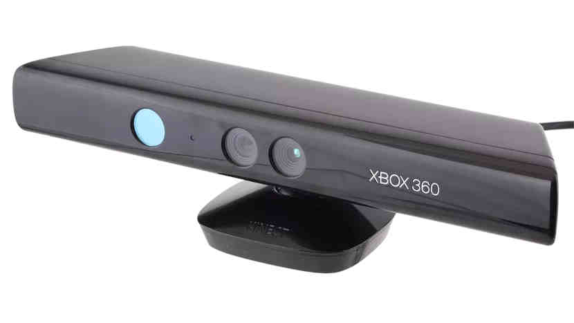 Microsoft Kinect sensor
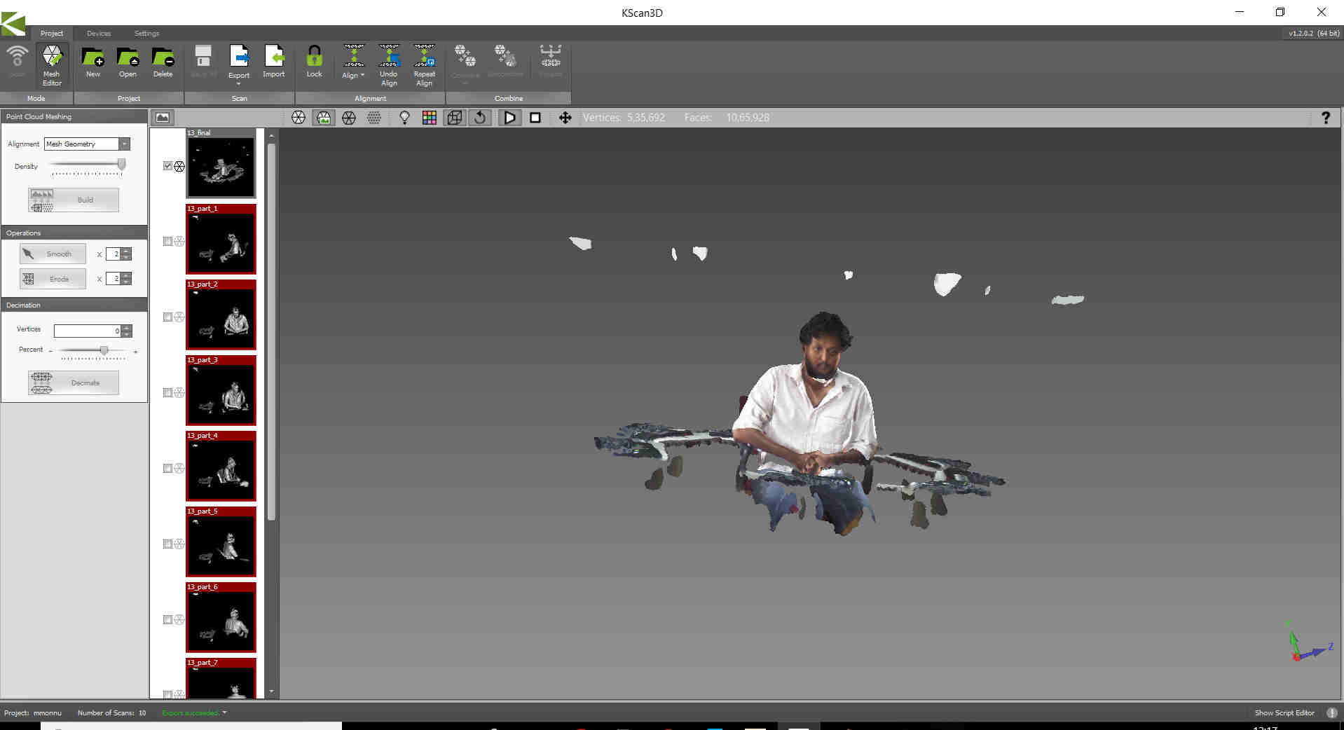 Scan preview in Kscan 3D. The images on the left pane shows various images taken continously by sitting on a rotating chair.Finally these images are stiched together to get the required 3D projection file.
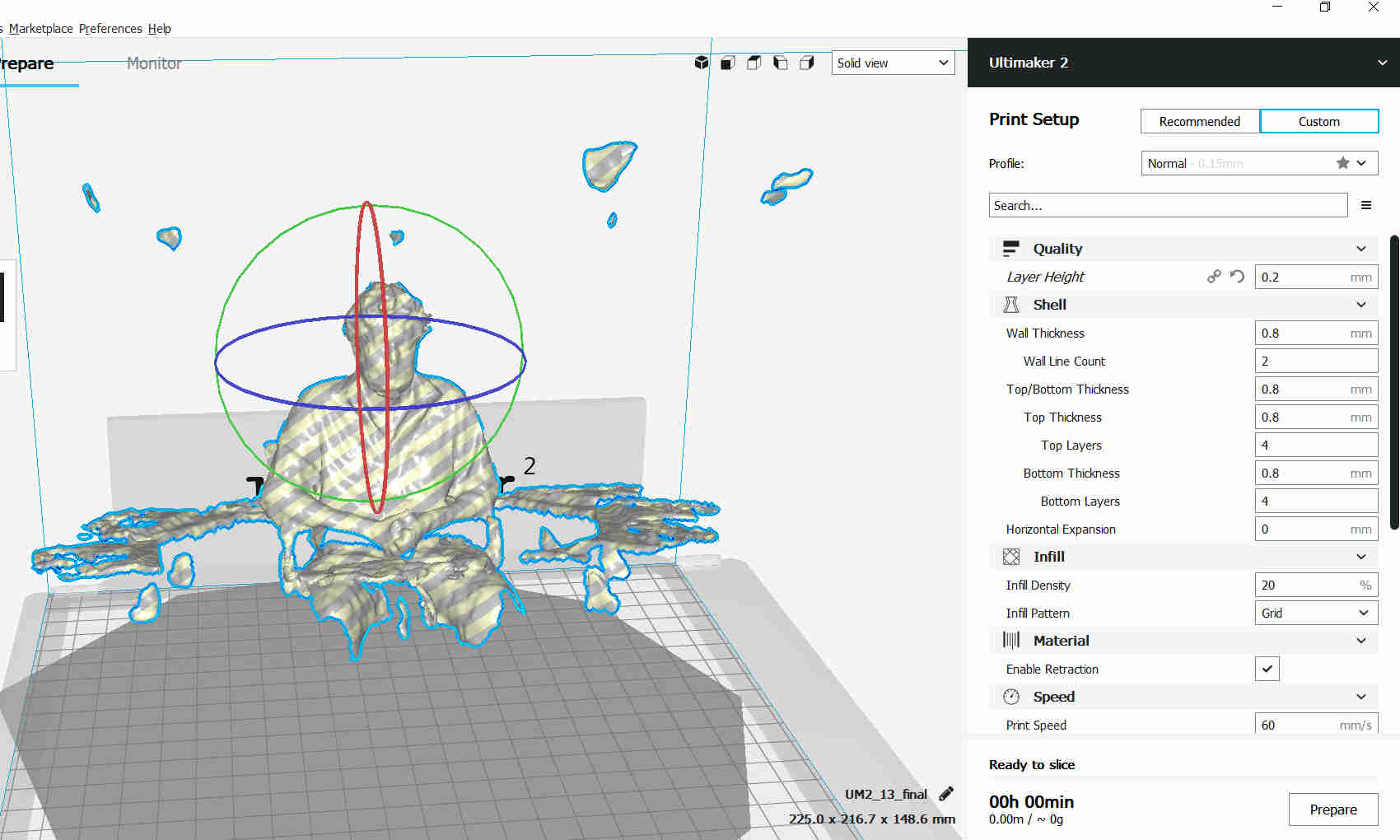 Image sliced in cura