5. Electronics production
Introduction
This week the aim was to make a PCB or Printed Circuit Board by ourself. With this we made an incircuit programmer for using it in coming weeks.
The Milling Machine
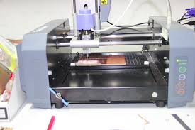
Source : http://wiki.fablab.is/wiki/Roland_Modela_MDX-20
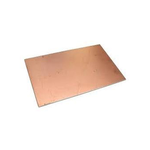
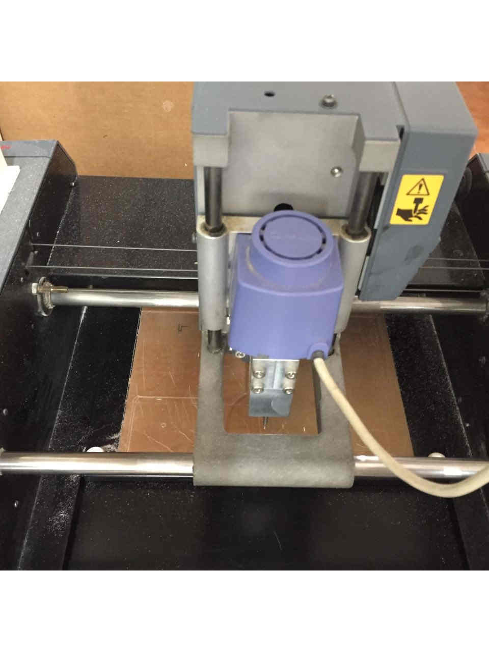
The machine that we used for milling process is Roland MDX-20.It a 3 DOF milling machine.The PCB is engraved as per input design on copper coated boards to create traces of the circuit. Spaces are predesigned in the circuit for placing the components. Circuits are milled in copper coated boards/blanks using an endmill of various tip dimensions. There are various types of PCBS, mainly FR1, FR2,FR3 and FR4. We have used FR1 board for milling. Roland MX 20 is my favourite machine in the lab.!
Source : amazon.com
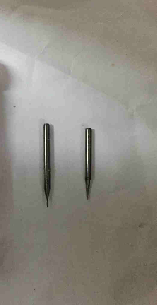
A V shaped bit (1/64) and 1/32 bit used.
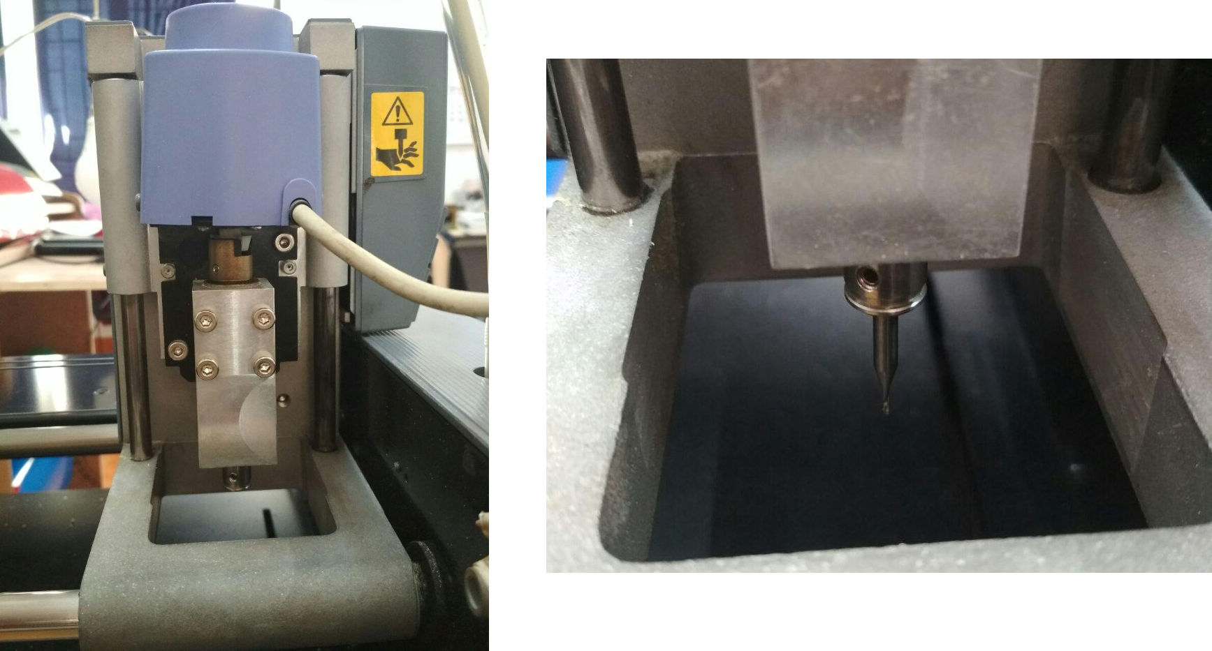
On left in blue is the end effector. The shaft in steel is connected to the collar.In right its shown the rotating shaft with the endmill.
Source :http://fab.academany.org/2018/labs/fablabtrivandrum/students/akhil-hari/5week/week5.html
It consists of a rotating end mill socket. The endmill with its socket is mounted to an end effector. The end effector moves on guided bars in X direction. It is made possible by pulling tightly drawn wires drawn between the sides. The base of the machine has a moving plate on to which we will paste the copper board during milling operation. The base plate along with the board is allowed to move in Y direction. Also the endmill tip can move in Z direction which decides the depth of cutting required.
Working
The machine is another numerically controlled machine. The realtime motion coordinates for the machine endeffector, the base plate are fed into the machine. These motion coordinates tell the machine to go where from where. This ultimately depends on the motion path designed by us to get the most optimised motion control. These motion plans are generated by Vector based softwares. Here we have used mods based machine control interface designed by Centre for Bits and Atoms MIT USA.
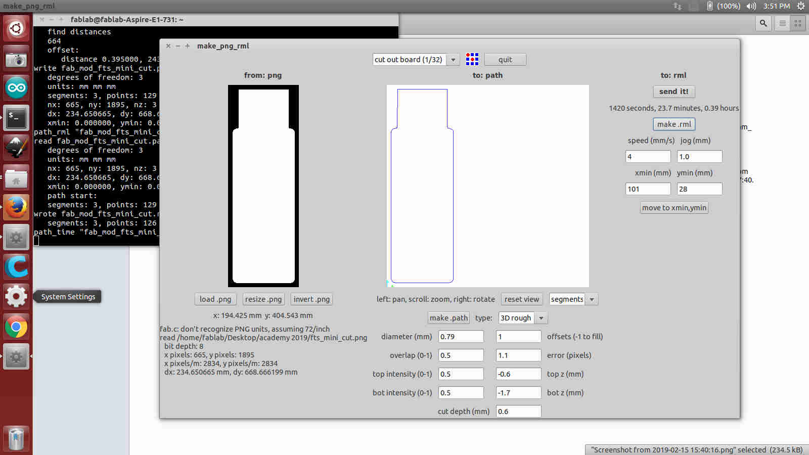
To begin we import the monochrome png of the circuit designed in Eagle. The mods use various Edge Detection algorithms to find the optimised cut path for the image.
To start we set the zero of the machine. We move the endeffector in vertical direction until sufficient space is left between the base plate to drop and screw tight the endmill. Before staring the milling,ensure that the cutting limits are within the board size.
The motion in one dimension of the endmill.The end effector along with the tip moves on guiding bars kept. The second motion is allowed in the base of the machine. Together they create the required motion in the 2D plane.
For milling, monochrome black and white png file of the cicuit board has to be given. The machine has a spindle unit that can move in 3 directions. The end of the spindle is attached to a collar. The bed of the miller moves in Y direction only. The bed shall be checked for any bends. We use solid carbide end mills for cutting the board. We used 1/32((1/32 of an inch -diameter of bit) and 1/64 mills for cutting the drills and cutting the traces respectively. These end mills are tightened to the spindle using Allen key. The machine has controls for moving the spindle up and down and a view option to move the bed towards the operator.
A sacrificial layer is attached to the bed using a double sided tape. The copper blank is then kept over this using the double sided tape. The image is sent to the machine using the FAB module.
Assignment 1- Characterisation of the Milling Machine
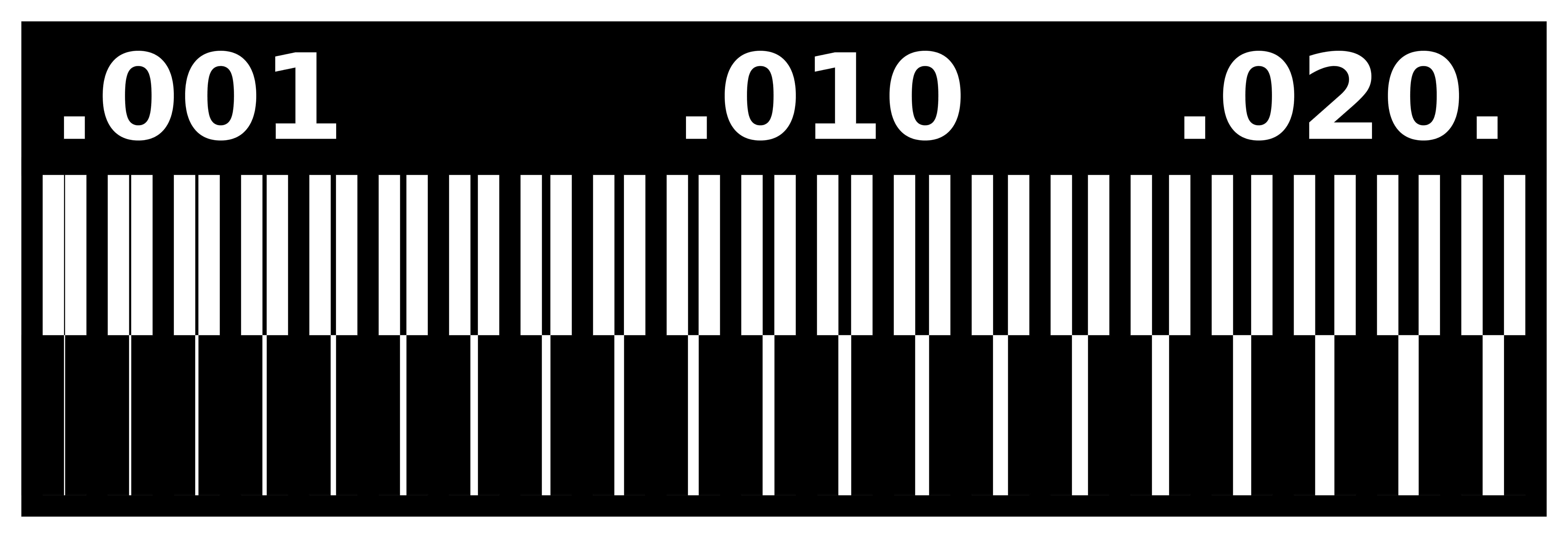
The real intention is here to mill a pattern to learn what should be width between traces and thickness of the trace. The machine reads the data as .rml file. The fab module will convert .png to .rml.
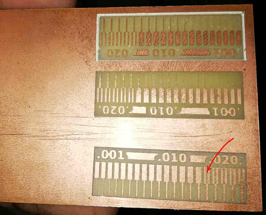
A monochromatic png picture file of good resolution (1000dpi) of the milling pattern is send to the FAB module of the machine. Both traces and the outer line of the PCB is milled seperately with different end mills. Here below the following images are used to mill the test board.
Settings were speed at 4mm/s and offsets at 4 and overlap at 50%.
 interior
 outer
outer
After milling
Issues
Since v bit used was broken at the tip, more of the depth portion was milled off in the first two cases. The v bit was repalced and then milled to give the bottom printed one. It can be seen that traces were milled when the gap between the traces is .016 inch which is equal to 1/64 of an inch or 16 mil, the end mill diameter.
Assignment 2- Making Tiny ISP
It involves following steps.
1) Mill the board as per the circuit.
2) Surface mount the electronic components by soldering.
3) Programme the PCB with another programmer using firmware source code avaialble in Brian’s page.
ISP
An ISP or In Ciruit Programmer is a device that can program other circuits. In future we would be using the PCB made here for the works. To make that we used the circuit diagram from Brian’s page.
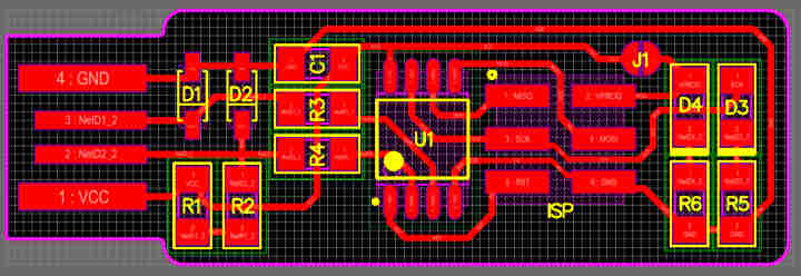
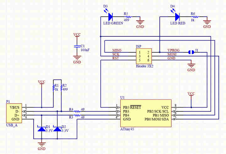 Schematic diagram
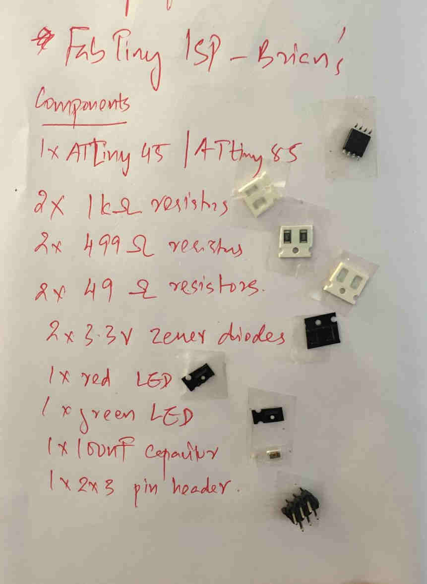
The list of items are 1. Micro Controller - Attiny 45 2. Resistor R1 - 1 KOhm 3. Resistor R2 - 499 Ohm 4. Resistor R3 - 49 Ohm 5. Resistor R4 - 49 Ohm 6. Resistor R5 - 499 Ohm 7. Resistor R6 - 1 KOhm 8. Zenor Diode D1 - 3.3V 9. Zenor Diode D2 - 3.3V 10. LED D3 - GREEN 11. LED D4 - RED 12. CAPACITOR C1 - 100nF 13. ISP HEADER - 3x2
The required electronic parts as per the above circuit are collected and fixed in a doubled sided tape. I never really imagined these parts were such small !
1) Milling the board
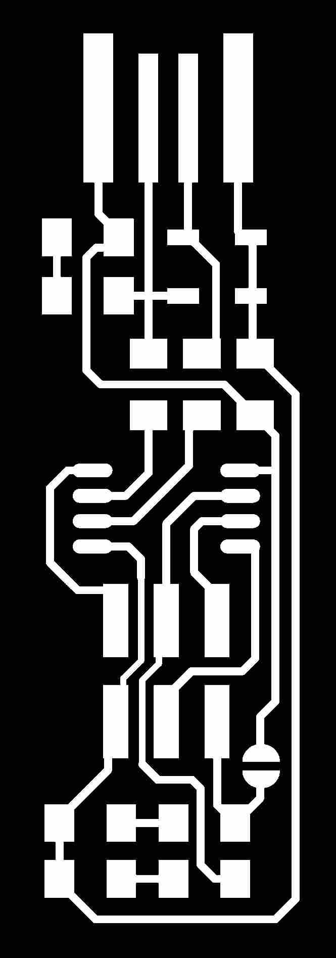 PCB trace milled with 1/64 end mill
 PCB outer milled with 1/32 end mill
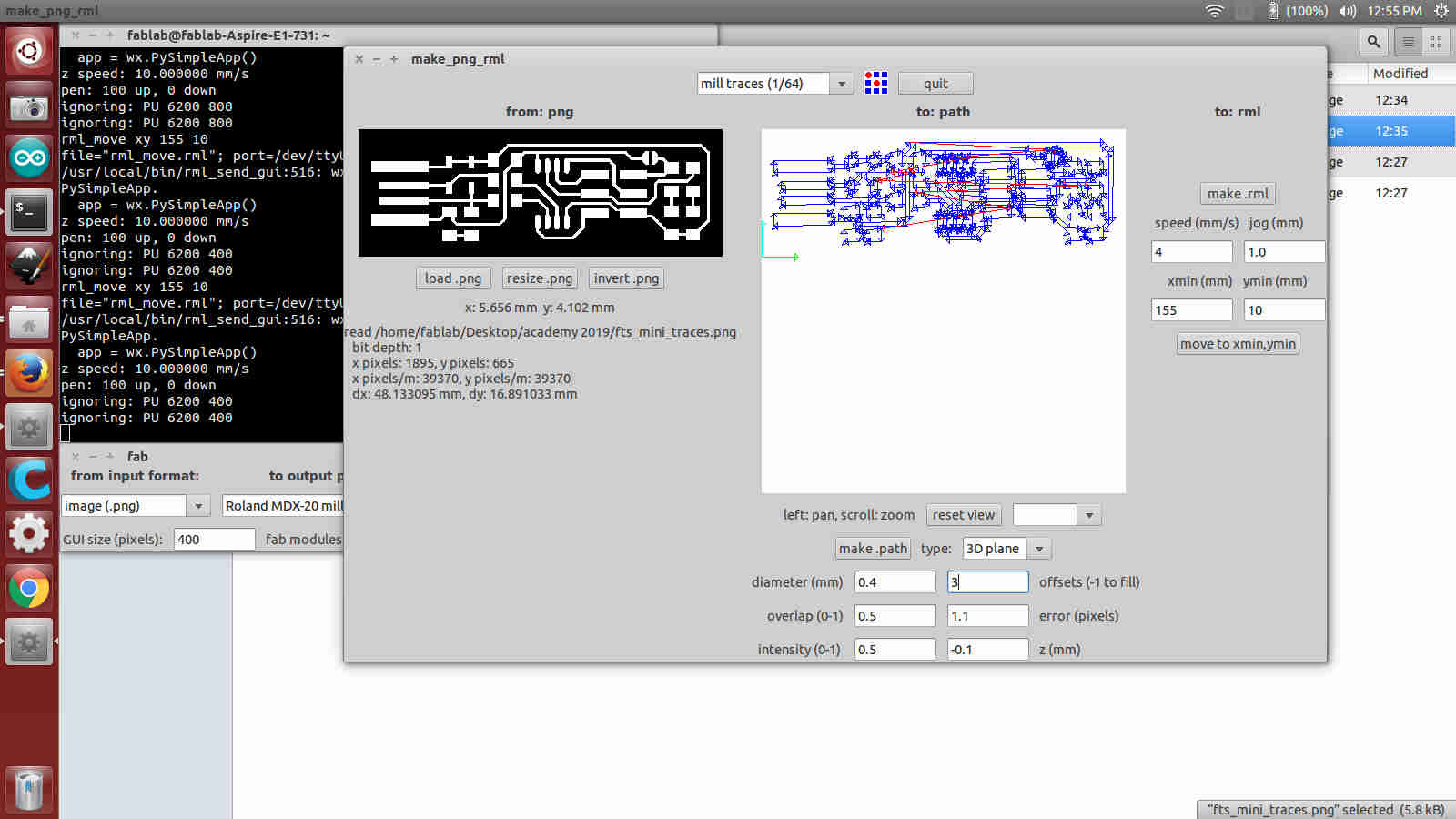 Trace Milling. The blue lines on the right shows the most optimised cut path generated by
 mods. It has to zoomed and checked for any possible break in the path. Red lines indicate the shift from one point to another.
The mill trace used is 1/64. Origins were selected. Number of offsets were adjusted to 3. The path of the mill arm is shown in blue. The depth of cutting is set as -0.1mm to make the trace. The speed is set as 4mm/s. As soon as the milling is over a vaccum cleaner is used to suck off the dust. Similarly the outer of the ISP is milled using 1/32 end mill as shown below.
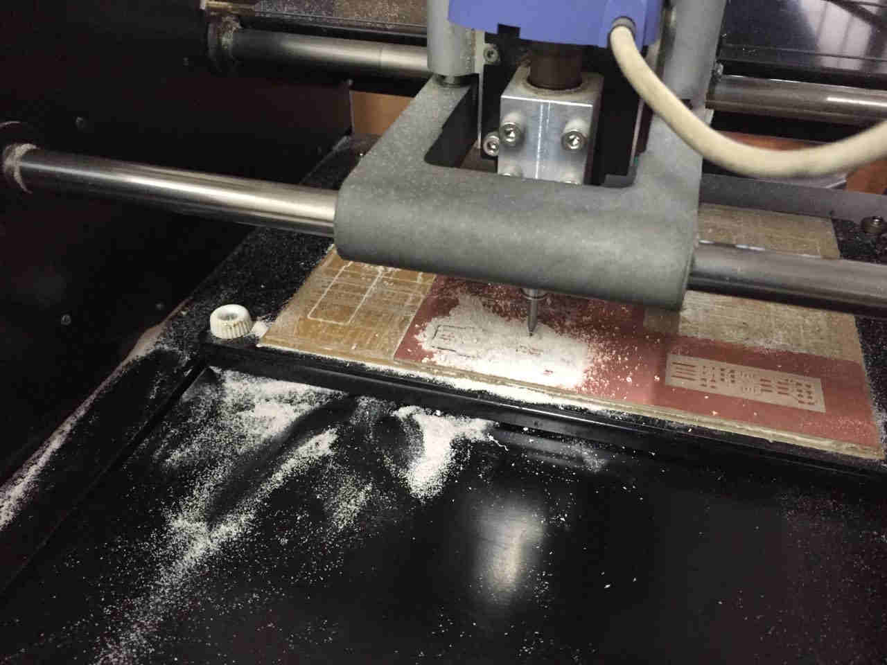 Milling in progress
Issues
Note: This is written in the final weeks. The milling that I did was not proper as we used V bit. The depth of cutting was slightly more as we can see large quantity of the milled up material.
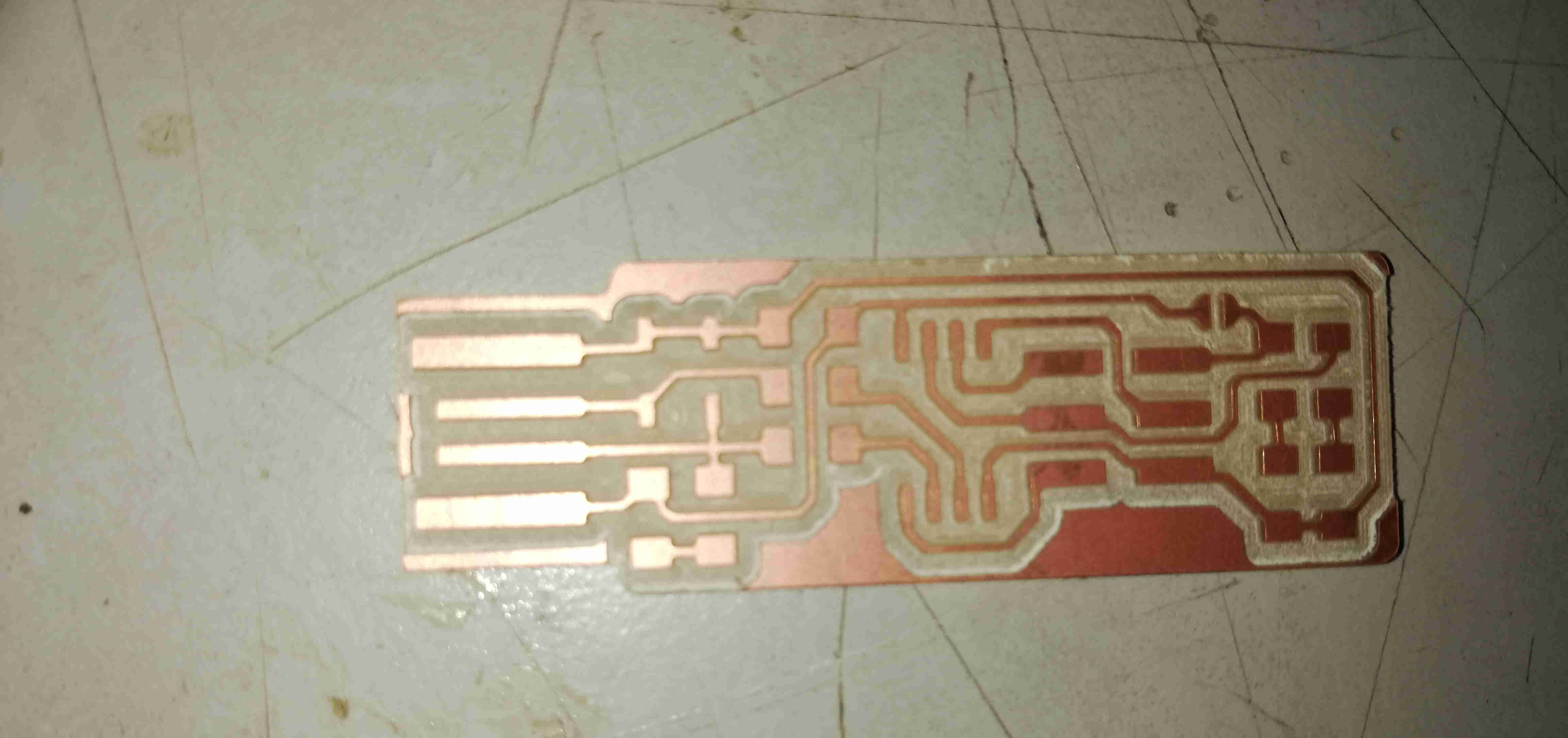 The milled board.
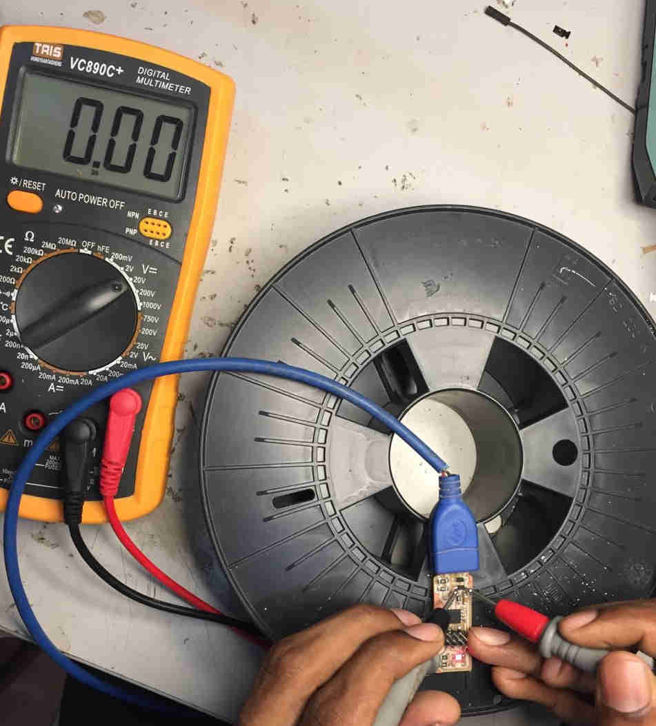
A multimeter is used to check whether traces have desired connectivity.
2) Soldering the components
The collected components were soldered onto the milled board. This was the most exciting part.
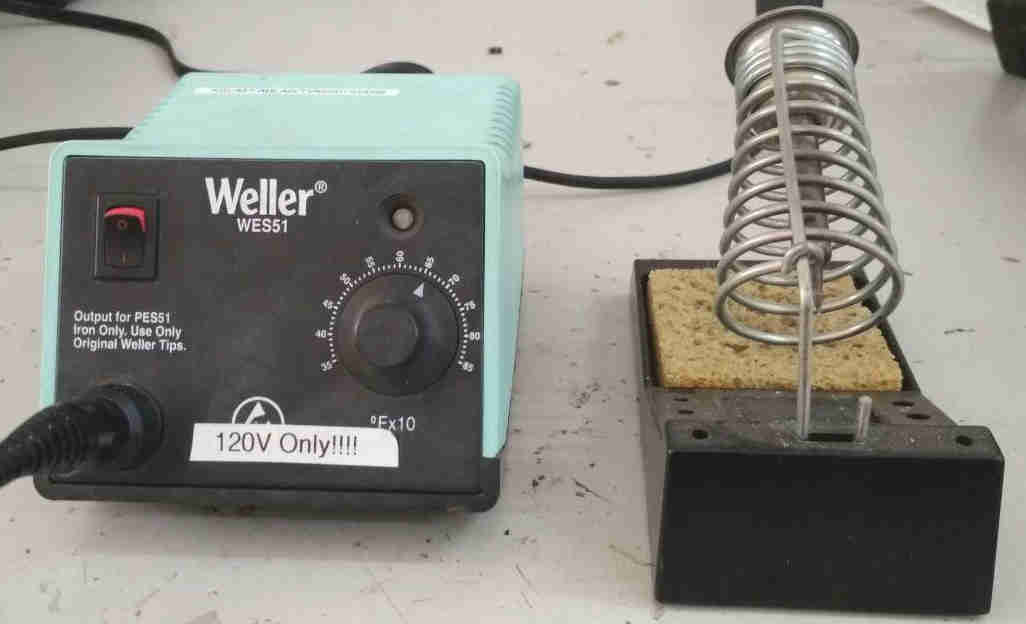 The soldering station enables us to keep the soldering iron at a constant temprature. There is a wet sponge to keep the solder iron’s tip shiny during soldering. Both solder and iron is kept at the place to be soldered. The solder after it melts will flow, which has to be creased and smoothened with the tip. Placing the component over this solder lump and again heating at its base will alow the component to slowly sink and settle in the hot solder.The soldering tips are to be kept shiny everytime before solder is applied, by rubbing with the wet sponge. During soldering there would be fumes, which can be vented out using a blower. For diodes and LED the signs were checked for the green line and connected accordingly.The top of the board was preheated and scraped gently to make the board’s surface clear for better contact with solder material.
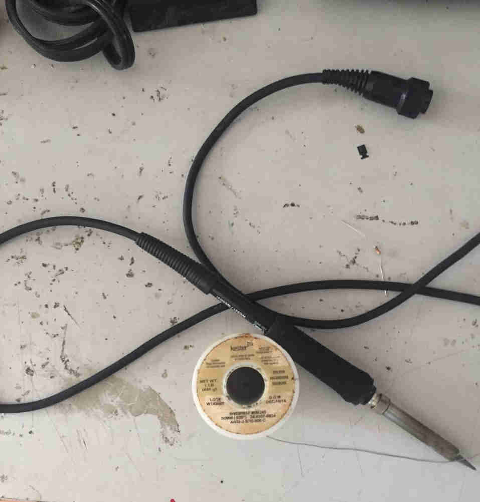 Soldering iron and solder material
 Blower with filter at its base
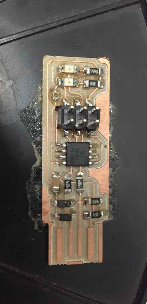
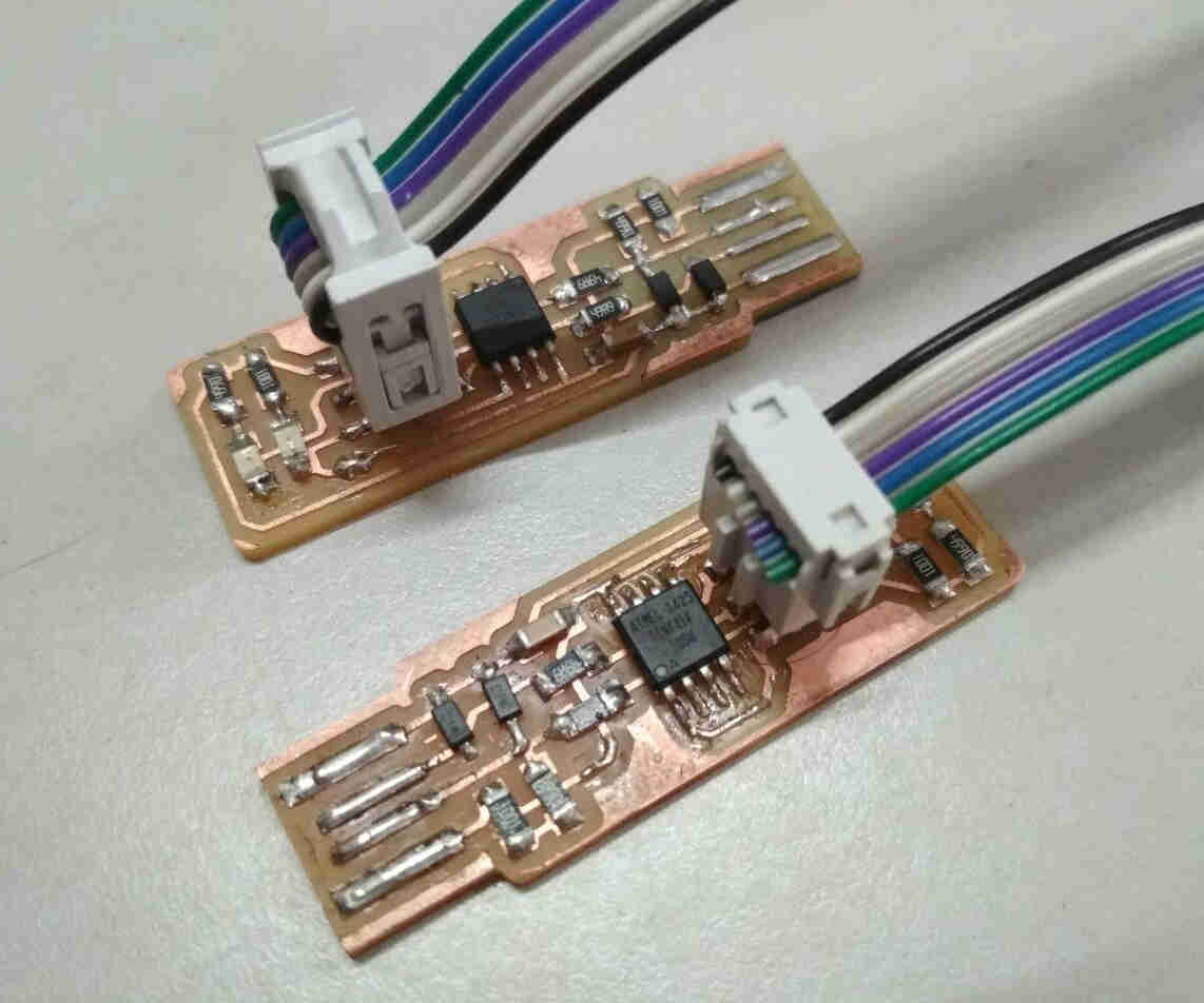
After soldering
Issues during Soldering
A multimeter is used to find whether the soldered connections are proper.
I found that the connection at the base of AT tiny has some issue that the solder at one of the base pins is short circuited.
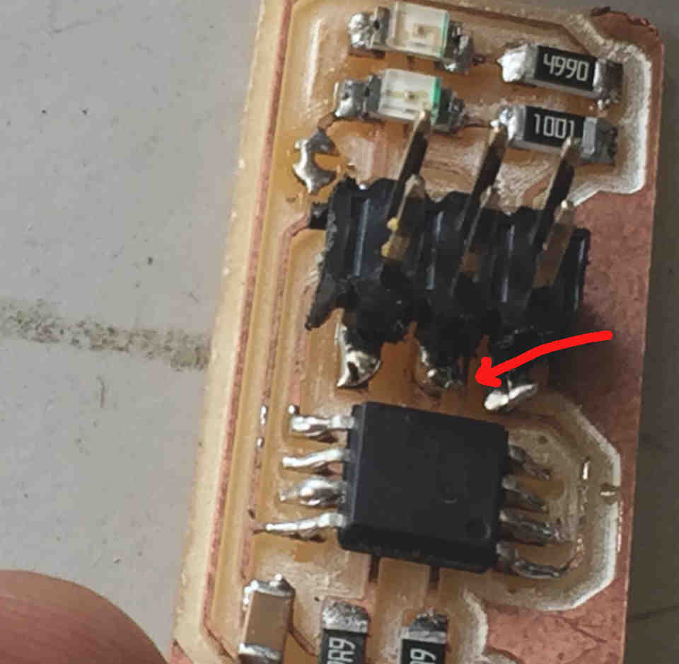 Crossover soldered at the base
It was fixed by slowly ripping off the extra solder by the tip of soldering iron and it worked !
Crossover soldered at the base
It was fixed by slowly ripping off the extra solder by the tip of soldering iron and it worked !
3) Programming the USBtiny
A programmer previously programmed can be used to connect our usbtiny to the computer using an ISP cable.
 Source : http://archive.fabacademy.org/2018/labs/fablabtrivandrum/students/akhil-hari/5week/week5.html#2
1)Download the firmware by command sudo apt install avrdude gcc-avr avr-libc make in the terminal.
2)Connect the programmer which is another usbtiny to our usbtiny and plug the programmer to the computer. This time the red LEDs in both the programmer shall be on.
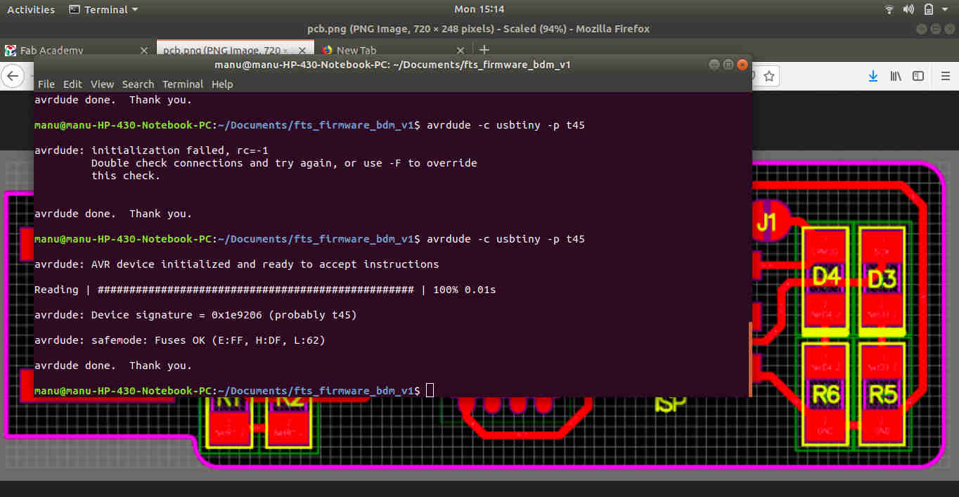
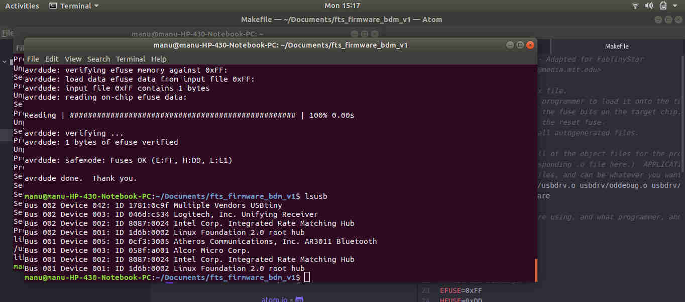
3)Extracted the folder fts_firmware_bdm_v1.zip.Opened a terminal in the above folder and gave command avrdude -c usbtiny -p t45 to initialise the AVR device.
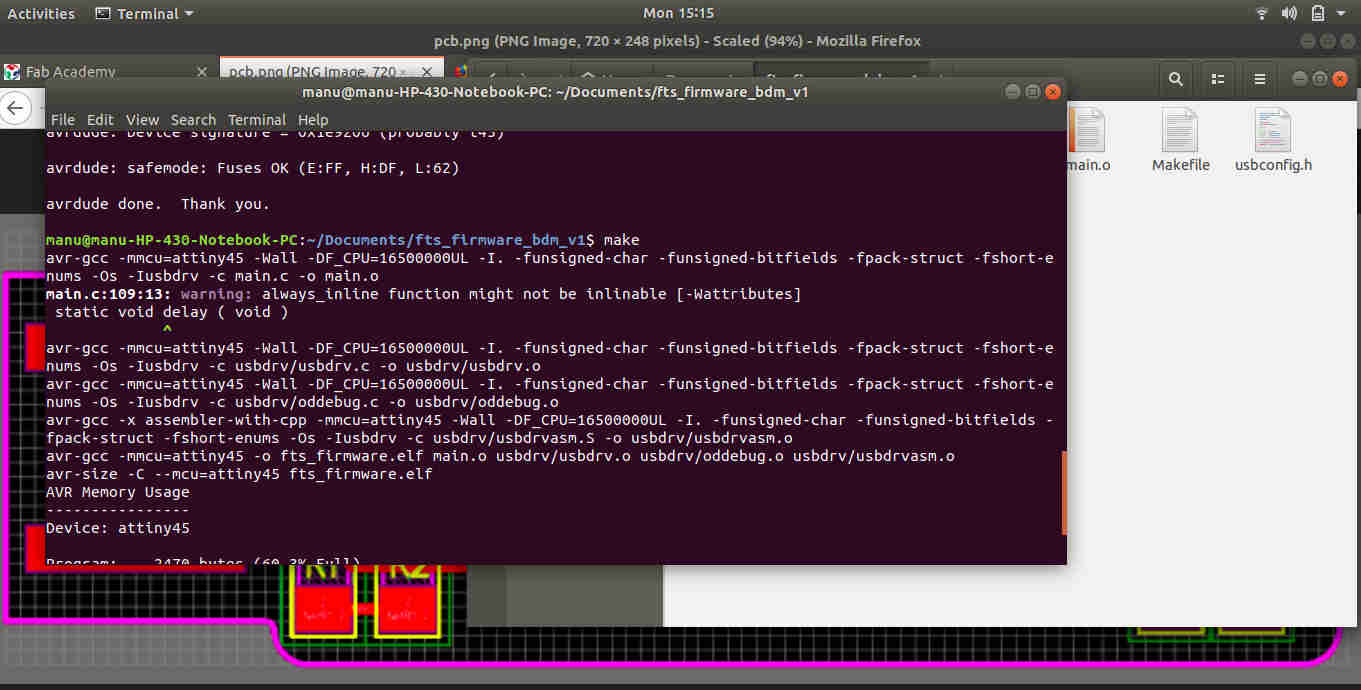
4) Command make generated necessary .hex file for flashing the firmware on to the microcontroller AT tiny 45 in our usbtiny.
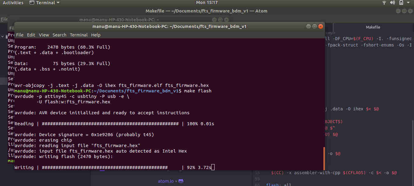
5)make flash will flash the necessary firmware on to our microcontroller.
6) make fuses to make fuse bits in the chip. Unplug the programmer and now plug directly our usbtiny to the computer. To check whether it’s detected by giving command lsusb in the terminal.
 7) Use
 rstdisbl to disable the reset switches.
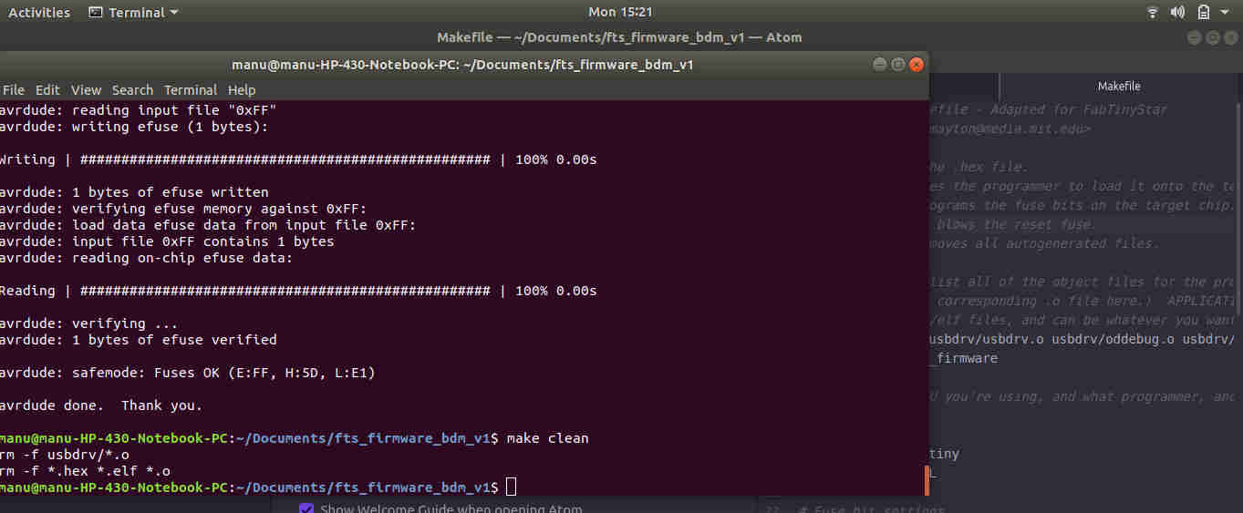
 8) Clear the files by
 make clean
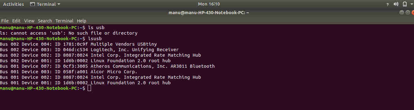
The usbtiny is finally programmed.
Issues with the USBtiny
Though I could program the usbtiny, I found that this is not being detected in my pc.Tried checking the connections using a multimeter.I found that the zener diode is not working. Replaced and found that still the usbtiny is not working. It took and hour to find that improper soldering at the base of the 1kohm resistor was the issue.
 Ps: I thank Yedu Sharon for his help in debugging.