12. Output devices
Last week we had interfaced an input device/sensor. This week it’s an output device. Professor Niel’s lecture gave a bird’s eye view on the various output devices like LED, Stepper motor, Brushless motor, Solenoid, Speakers etc. I decided to interface an 16X2 LCD panel to the MCU circuit. Also I would be using an LCD display for my final project. This week’s working will allow me to familiarize with it.
Liquid Crystal Display
I have used a 16X2 LCD as the output device.
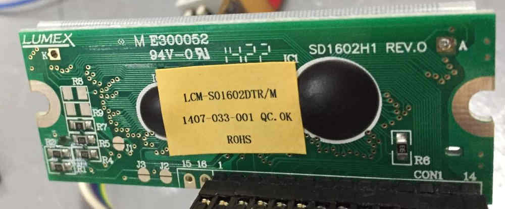
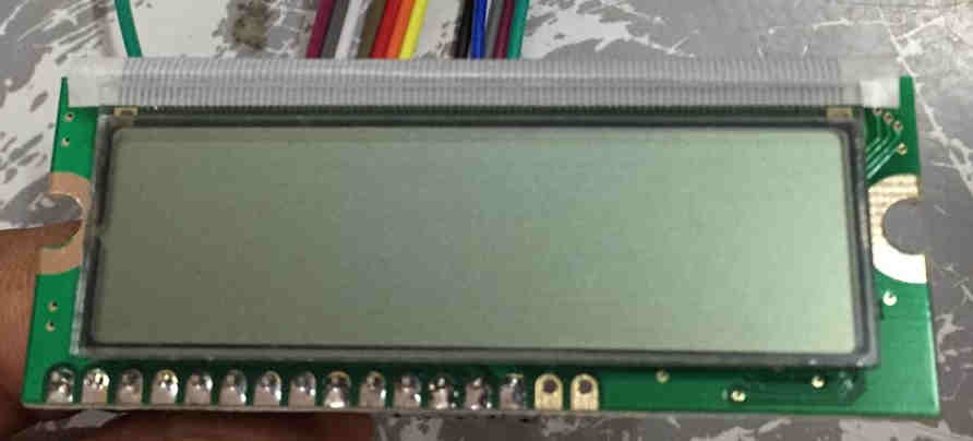 The display
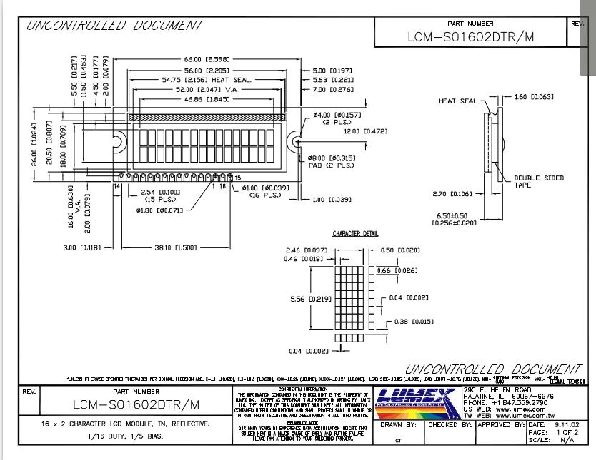
 The data sheet of the LCD
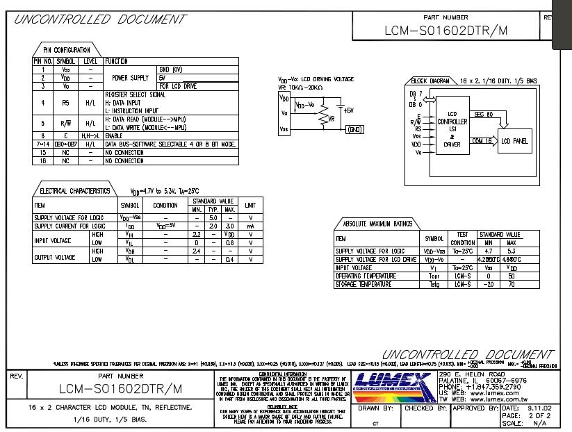
LCD module consists of 16 pins. The various pins are as follows:
Pin 1: Ground - PowerSupply
Pin 2: Vcc- PowerSupply
Pin 3: Contrast pin- A potentiometer is connected across to change the contrast. In this case we made it not variable.
Pin 4: Register Select pin. It determines the type of data send to the LCD. A high signal will be a data input and low signal is instruction input.
Pin 5 :This the Read/Write pin. This decides whether to cause LCD to read or to write. A low value will make it to read and viceversa. Usually we ground it to read it always.
Pin 6 : This is the Enable pin. Turning this pin on will make the LCD to start receiving instructions. This pin is connected to digital pin of the MCU.
Pin 7 to 14 :They are data pins.The states of these pins (high or low) are the bits that we are writing to a register when you write, or the values we are reading when you read.
The data sheet for HD44780U (LCD-II) driver enabled LCD display was referred. The Hitachi-compatible LCDs can be controlled in two modes: 4-bit or 8-bit. Presently we are trying to display text, which can be conveniently controlled using 4 bit operation. This means that only 4 data pins are necessary. Here we have used pins from 11 to 14.4 bit mode is usefull for saving pins, but only has a refresh rate of 74ms. 8 bit mode is usefull for a fast refresh rate (5ms), usefull for displaying custom character animations.
Pin 15 an 16 are used for controlling the backlight. Our LCD module doesn’t have that feature. Hence these pins are left not connected.
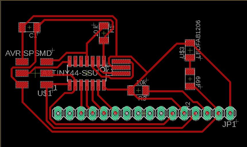
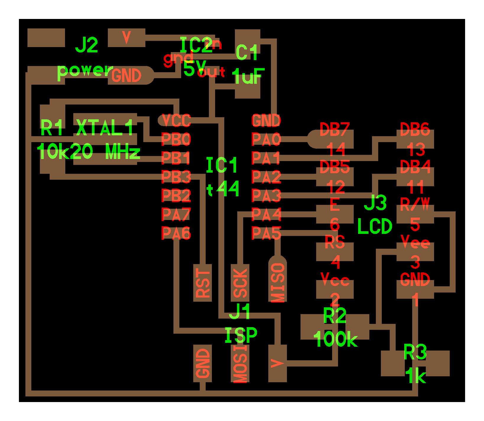
Designing the PCB
The circuit board was designed using Eagle software.
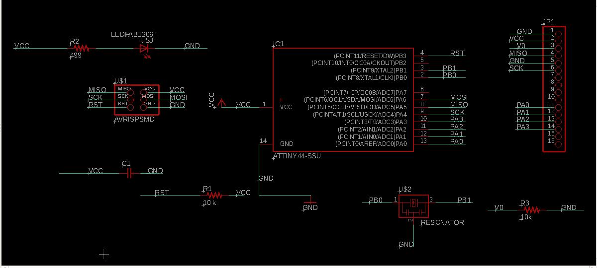 Schematic
 The 16 pin header was provided for connecting the LCD module. Though only 14 are required.
Data pins of LCD 11,12,13 and 14 was connected to the PA0,PA1,PA2 and PA3 respectively.
Error commited
After milling and soldering I just realised that I forgot to add potentiometer. This was later fixed by adding 100k and a 1k resistor across as per the Niel’s board.
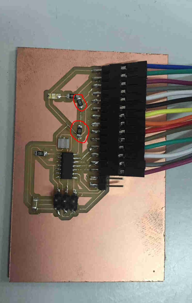 Additional resistors added
Files here
Programming the MCU
A program was written in the Aurdino IDE to print “Hello World”. The reference was obtained from this site.. The program was flashed onto the MCU.
      // include the library code:
      #include <LiquidCrystal.h>

      //initialize the library by associating any needed LCD interface pin
      // with the MCU pin number it is connected to
      const int rs = PA5, en = PA4, d4 = PA0, d5 = PA1, d6 = PA2, d7 = PA3;
      LiquidCrystal lcd(rs, en, d4, d5, d6, d7);

      void setup() {
      // set up the LCD's number of columns and rows:
      lcd.begin(16, 2);
      // Print a message to the LCD.
      lcd.print("hello, world!");
      }

      void loop() {
      // set the cursor to column 0, line 1
      // (note: line 1 is the second row, since counting begins with 0):
      lcd.setCursor(0, 1);
      // print the number of seconds since reset:
      lcd.print(millis() / 1000);
      }
It did work !
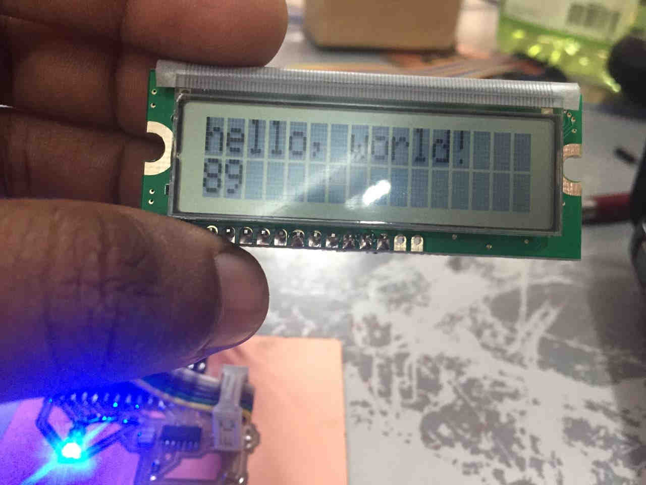 The timer started counting.
Video
Creating Custom characters in LCD
I learnt that custom characters can be printed by giving specific bit patterns. These patterns are found out by using the method of drawing the pixel array and assuming the bit value for the pixel which is ON as 1and the pixel which is off as 0.
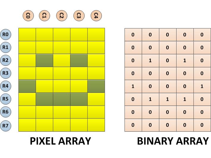 The 8 byte long character array for the above shown custom character can be defined in the code as given below;
          {

            0b00000,

            0b00000,

            0b01010,

            0b00000,

            0b10001,

            0b01110,

            0b00000,

            0b00000

          };
The function lcd.createChar() can be used to write a custom character to the required location in the CGRAM. The function has two parameters in which the first parameter is the location in the CGRAM memory where the character array corresponding to the custom character need to be stored and the second parameter is the character array itself.
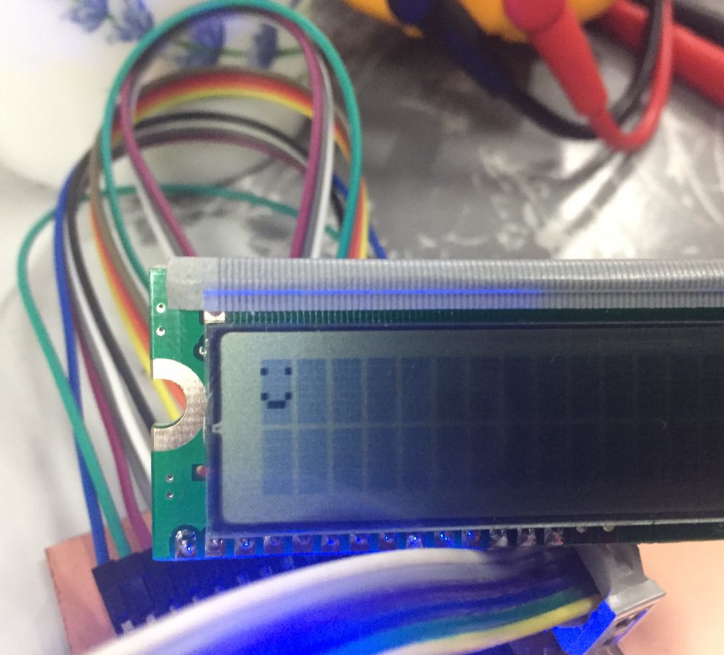
Tried with the following program to create a smiley.
// include the library code:
#include <LiquidCrystal.h>

// initialize the library by associating any needed LCD interface pin
// with the arduino pin number it is connected to
const int rs = PA5, en = PA4, d4 = PA0, d5 = PA1, d6 = PA2, d7 = PA3;
LiquidCrystal lcd(rs, en, d4, d5, d6, d7);
byte smiley[8] = {
  B00000,
  B10001,
  B00000,
  B00000,
  B10001,
  B01110,
  B00000,
};

void setup() {
  lcd.createChar(0, smiley);
  lcd.begin(16, 2);
  lcd.write(byte(0));
}

void loop() {}
lcd.createChar(0, smiley) creates the custom character array smiley and stores in the 0 th location of the CG RAM of the LCD controller from where it can be displayed by calling lcd.write(byte(0))
Click to download updated eagle files
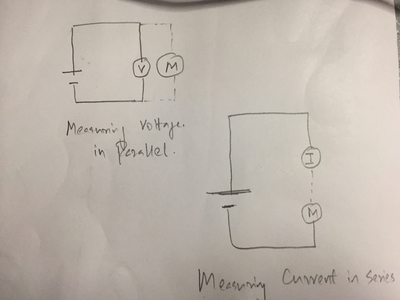
Group Assignment - To measure power consumption of an output device
Power consumption of a device = Voltage X Current
To measure current drawn in a circuit/electronic component a Multimeter has to be connected in series to the circuit. If we are measuring Voltage we connect the multimeter in parallel position.
The Output board was connected in series with the multimeter with the external power supply of 4.9V and the current drawn was measured using a multimeter in series.
Video of Testing power consumption of board
Power consumption of the board = 4.9v X 15.85mA = 4.9x0.001x15.85=0.0777Watts or 77.7milliWatt
Next the board was connected to LCD and the current was again measured as above
Video of Testing power consumption of LCD display
Power consumption of the board + LCD = 4.9v X 131mA = 4.8X.001x131 W =.642 Watts or 642milliWatt
Therefore power consumption of the LCD screen = 642-77.7 = 564milliWatts
References
- https://www.arduino.cc/en/Tutorial/LiquidCrystalDisplay
- https://www.engineersgarage.com/embedded/arduino/how-to-display-smileys-on-lcd-using-arduino
- https://www.arduino.cc/en/Reference/LiquidCrystalCreateChar