18. Wildcard week
Aim
This week’s aim was to produce something with material composites using the tools of digital fabrication that we have learnt over past weeks.
Composites
Composite materials are those materials that are made by combining two materials that has two different properties, but when combined exhibit the desirable properties of both the materials. The best example is reinforced cement concrete. Here concrete is best designed to take compression but is weak in tension.Reinforcing steel is weak in compression but is good with tension. These two are beautifully arranged to give a material that is both good in tenison and compression. Here with the available resources in the lab, I decided to work with jute and epoxy resin.
Jute and epoxy
The SDS and TDS of the Epoxy resin, that we used in the lab was not easily available. From amazon (link above) we found the following
1. Specially created aditya epoxy resin 33 to make transparent statues, murties
2. Less viscosity like water
3. Can cure in 30 minutes if heated at 65 degree centigrade and poured
4. Will cure at room temp in 24 hours
5. Non - yellowing
It has two parts part A and part B, those two are to be mixed in 2:1 proportions.Epoxy was handled with care. Extra caution was taken to avoid direct contact of the material with body.
Jute we used was available from the local market.
Boomerang
 Image Courtesy : https://www.australiathegift.com.au/shop/traditional-boomerang/
My idea was to make a boomerang from epoxy jute composite. Boomerang is an aerofoil that would return to the the thrower in a special return path. Typically a boomerang has two edges that enable it to develop the aerofoil action. These were used by Australian tribesmen for hunting. Modern version of these are available made of ABS, carbon fibre etc.
The plan was to make a booemrang that had jute fibres to make it light.
Inorder to have the aerofoil effect the boomerang has to have a round leading edge and sharp trailing edge. Upon motion through the fluid the aerodynamic forces will act on it. The normal component of this force is called ‘Lift’. This is the force that make the boomerang float in fluid or air. Every flying machine part will have flight components designed for aerofoil effect. Let it be wings of an aeroplane or blades of a helicopter. Inotherwords boomerang is an aerofoil blade without conenctions to the spindle. It rotates and fly on its own path.
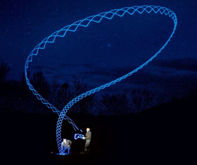 ImageCourtesy:https://www.reddit.com/r/pics/comments/65c3fi/long_exposure_of_the_path_of_a_boomerang/
The picture above shows the lit path of a boomerang taken with long exposure in a camera.
ImageCourtesy:https://www.reddit.com/r/pics/comments/65c3fi/long_exposure_of_the_path_of_a_boomerang/
The picture above shows the lit path of a boomerang taken with long exposure in a camera.
The design
The main hurdle with the design was that,the aerofoil shape cannot be made parametrically. It had always been a trial and errror process. Anyway I searched for any possible parametrical models for the boomerang.
Finally I found this one, Parametric Model for Boomerang and I decided to follow it. Atleast I can start with the work rather than working without a preconceived model.
As usual I began with the sketch outline in Fusion 360.
From the reference there were 3 methods for generating the shape. I chose the first one. Two profiles are made in the required thickness and Loft tool is used to connect these two to have a smooth and curved edge.
Steps in Design
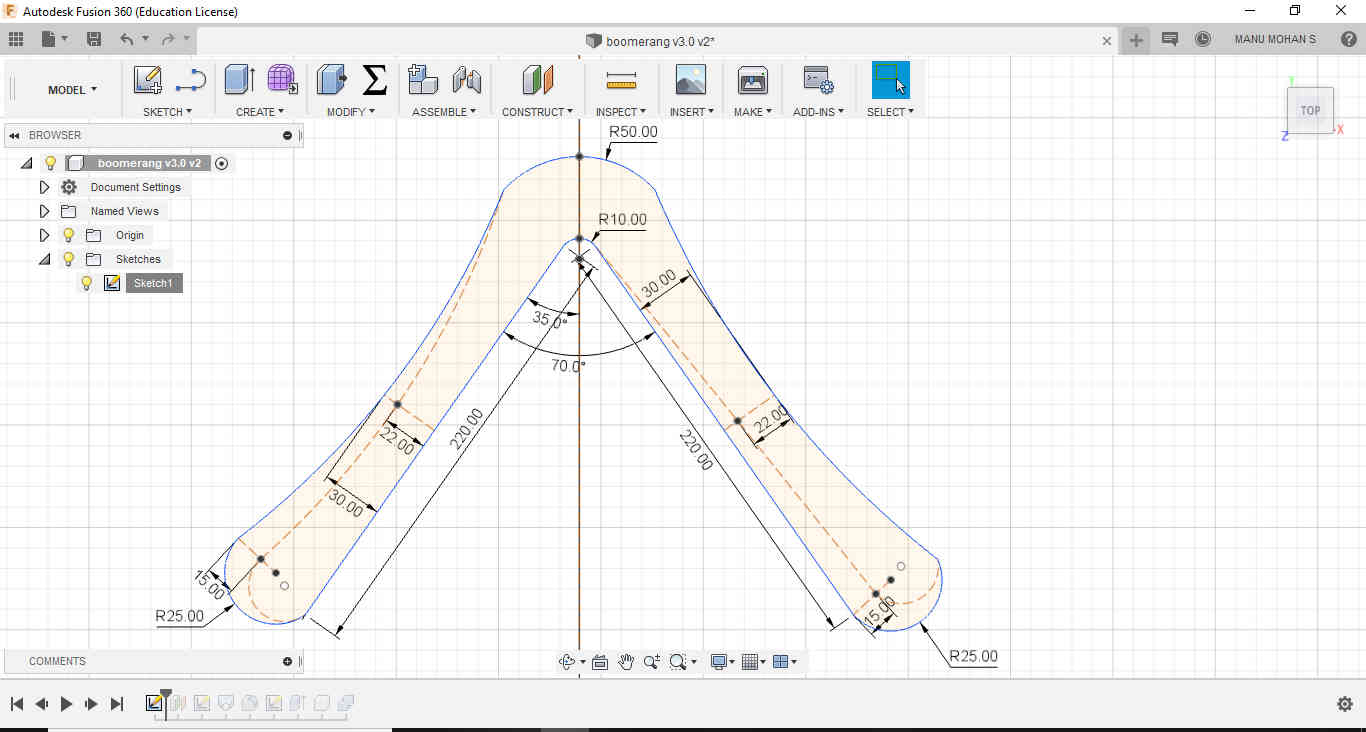 A primary outline sketch was constructed
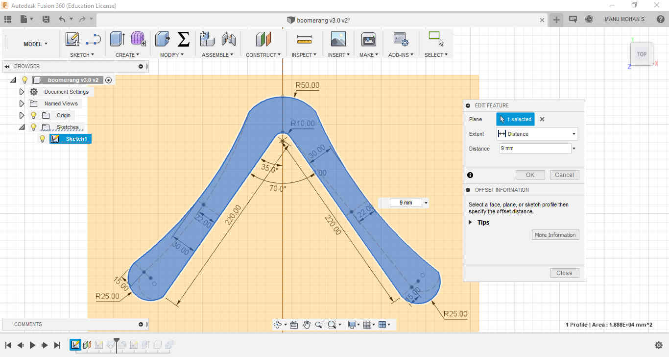
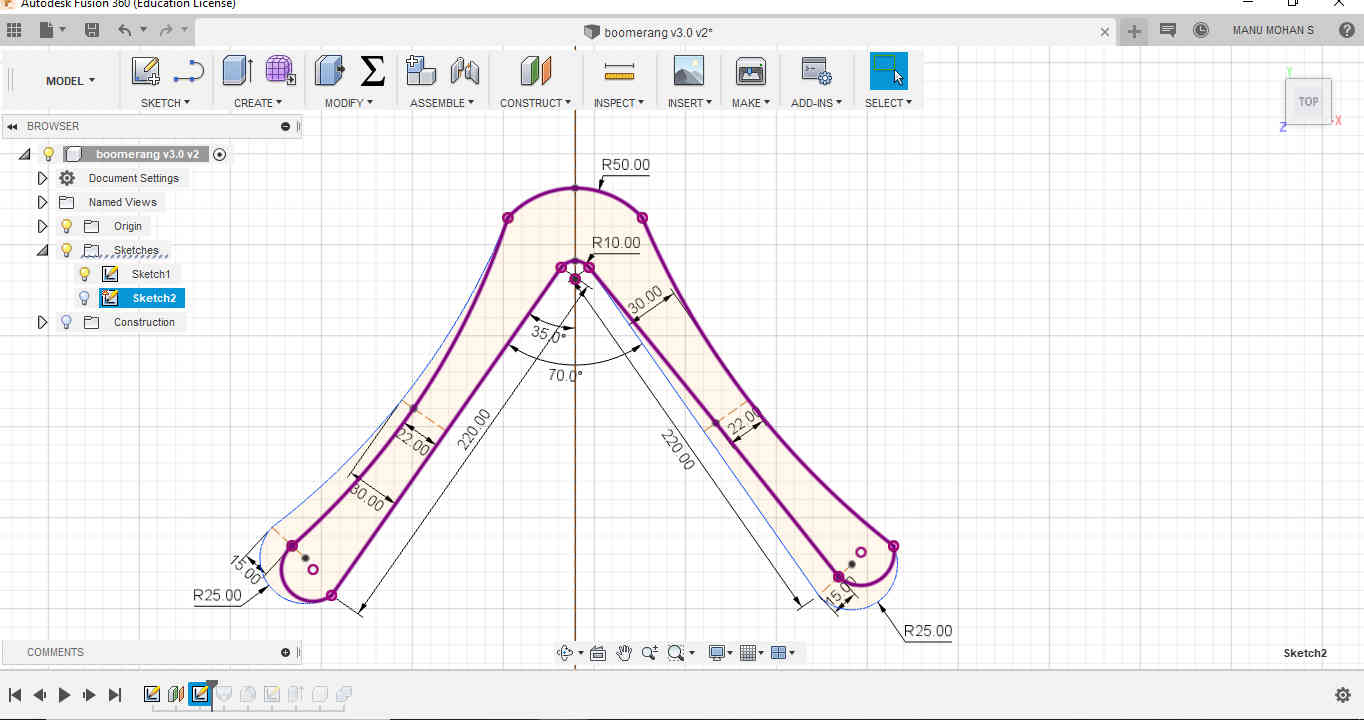 A secondary outline sketch was made on a constructed new plane at the intended thickness of 9mm for the boomerang.
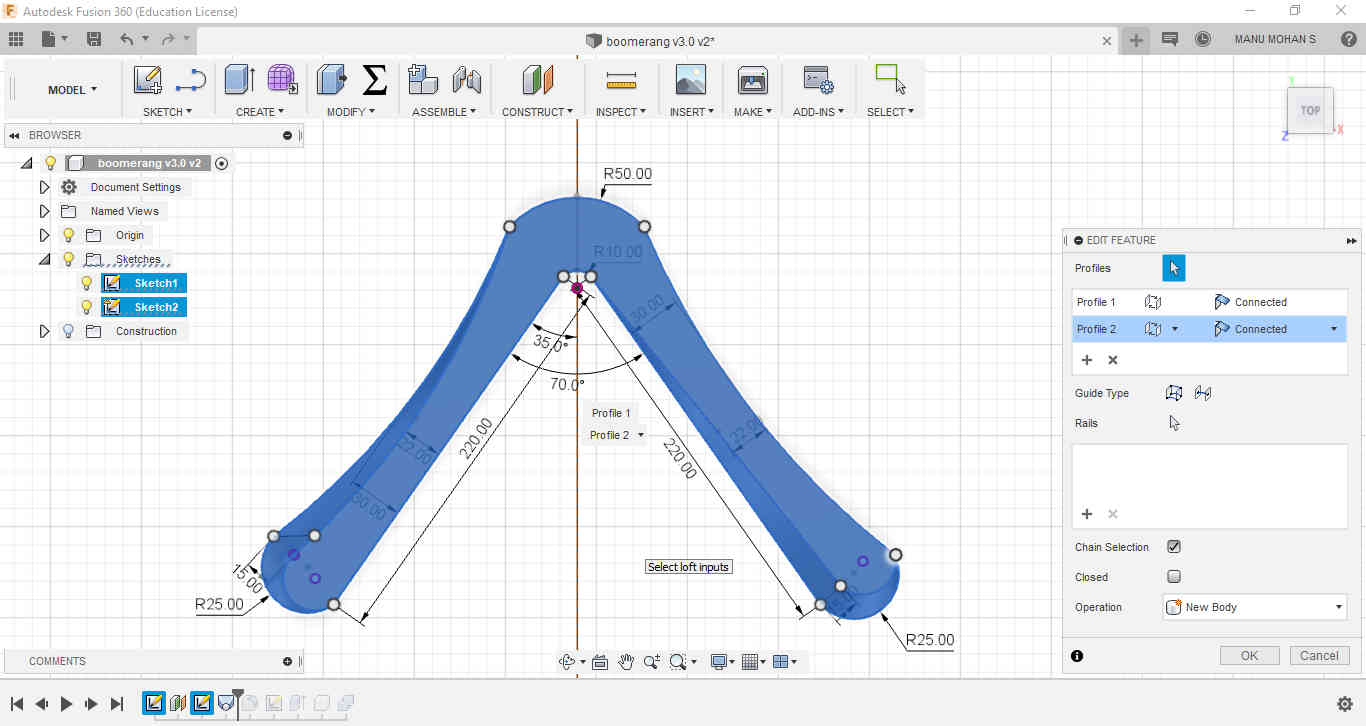 Loft was used to connect both the sketches
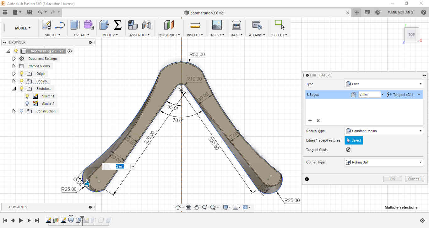 Fillet is used to round the edges of the Boomerang
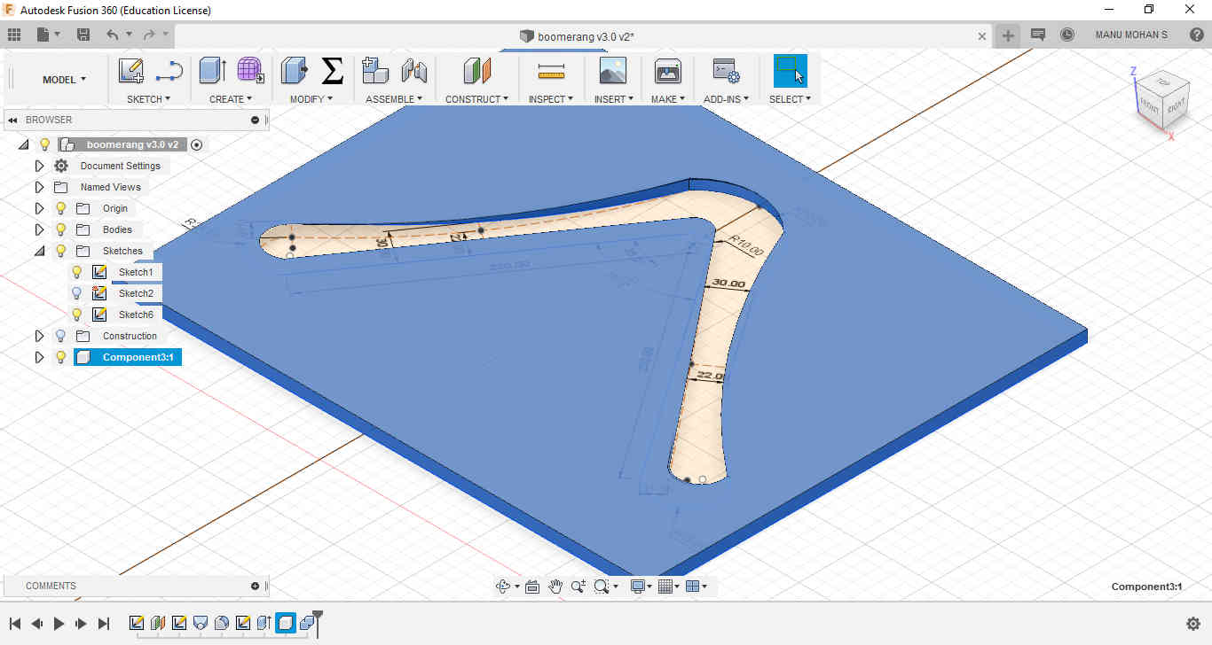 A box is made and Combine command with Cut function will give us the necessary mould for milling purpose.
files here
After this the design is exported as an stl file for milling purpose.
The mould is to be directly milled in the 18mm plywood stock.
For making CAM files a software called Vectric PartWorks was used. As usual the milling was done in two stages Rough cut and finish cut. Rough cut was made with 6mm endmill bit and finish cut with 3mm endmill.
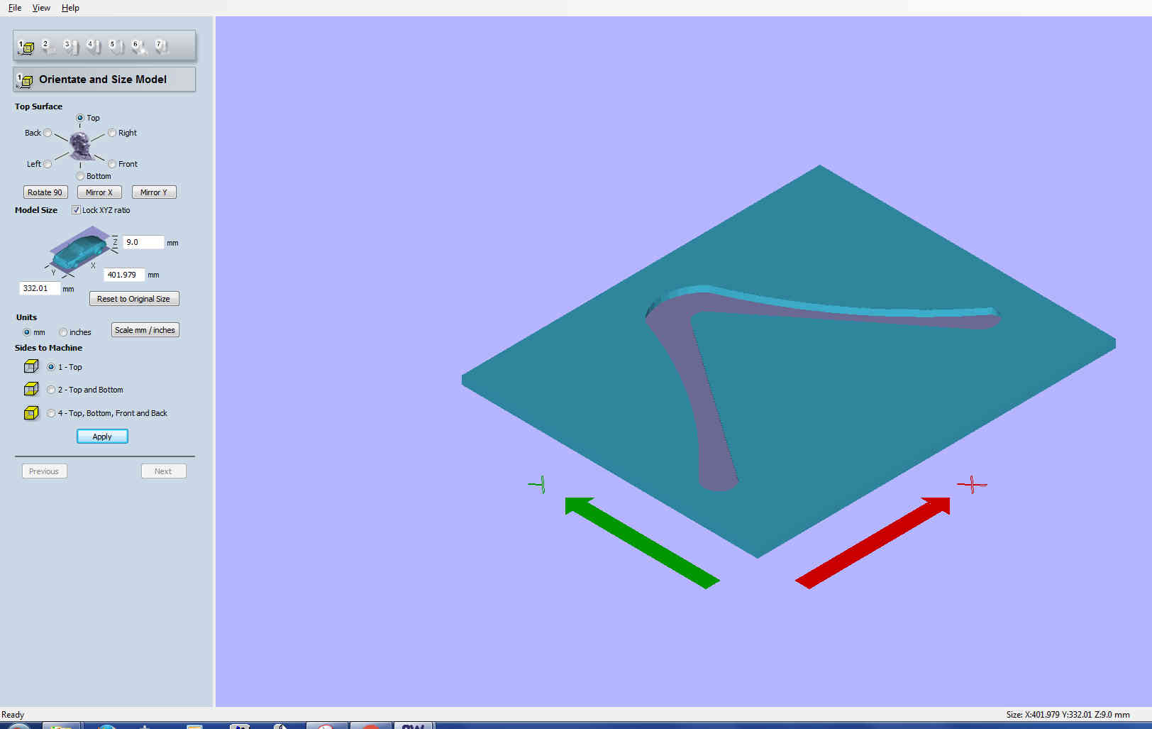 Orientation is set
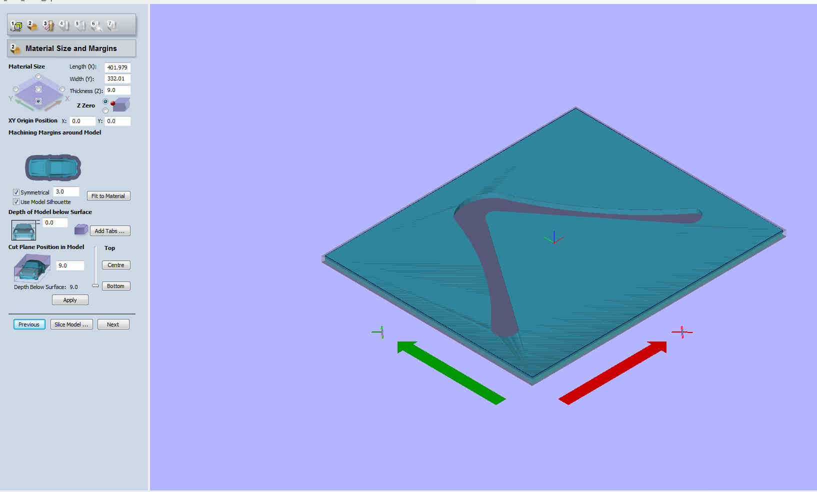 Material size and margins
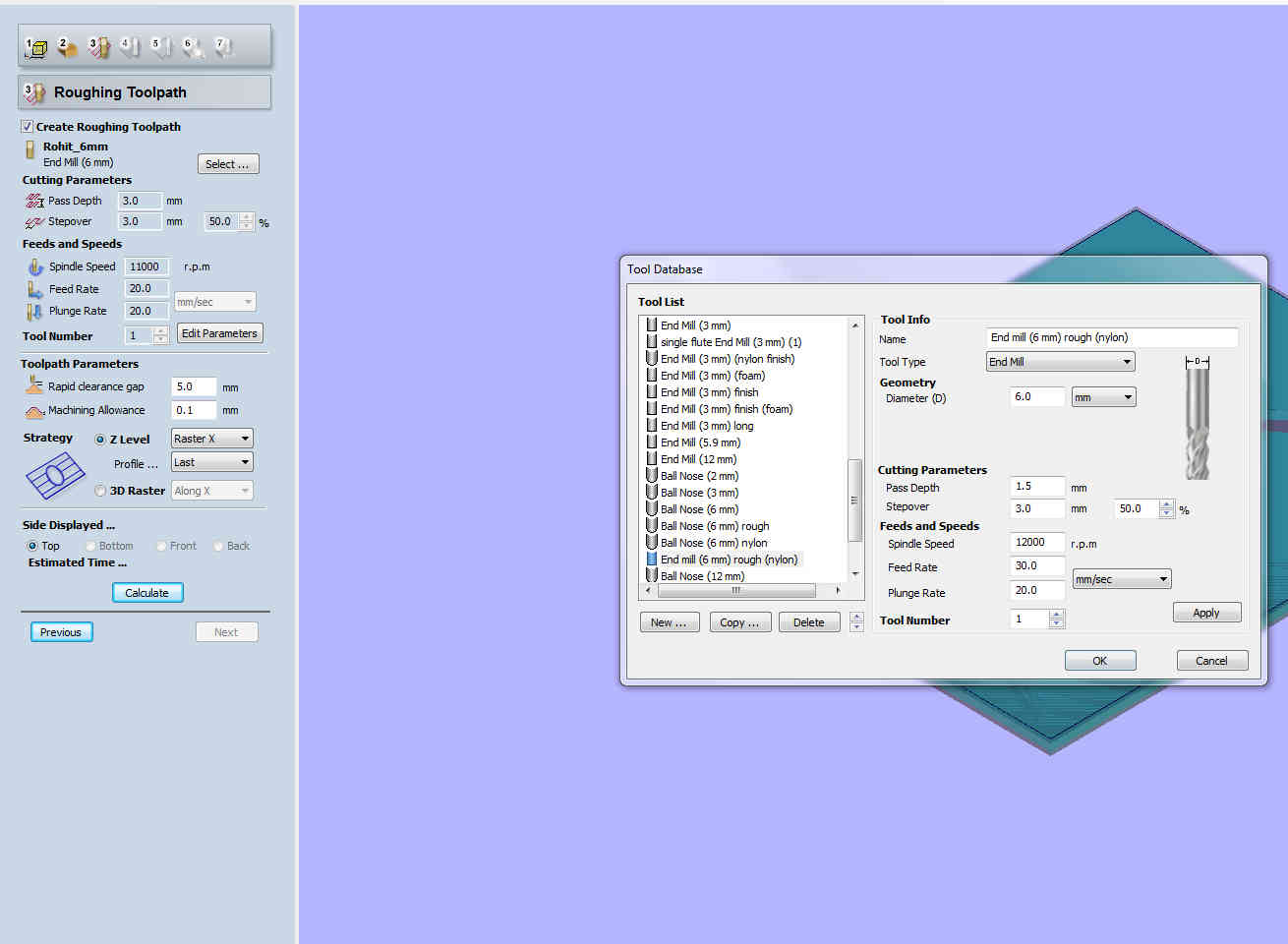 Defining path for Rough Cut
 Finishing Tool path is defined
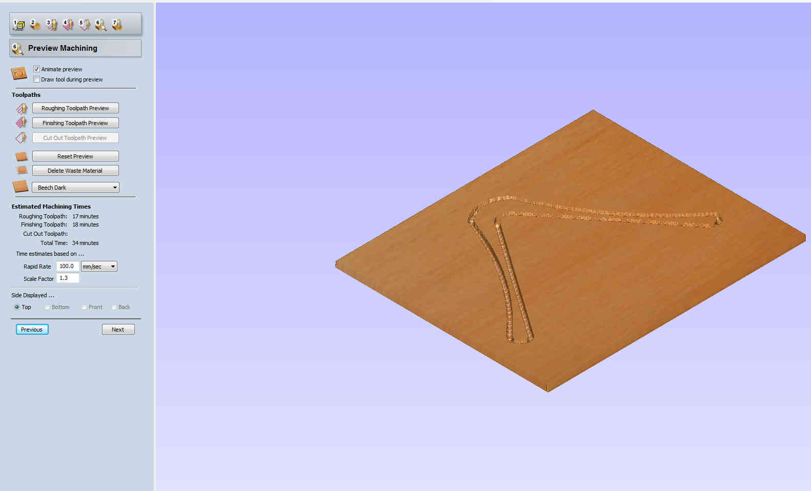 Model Preview
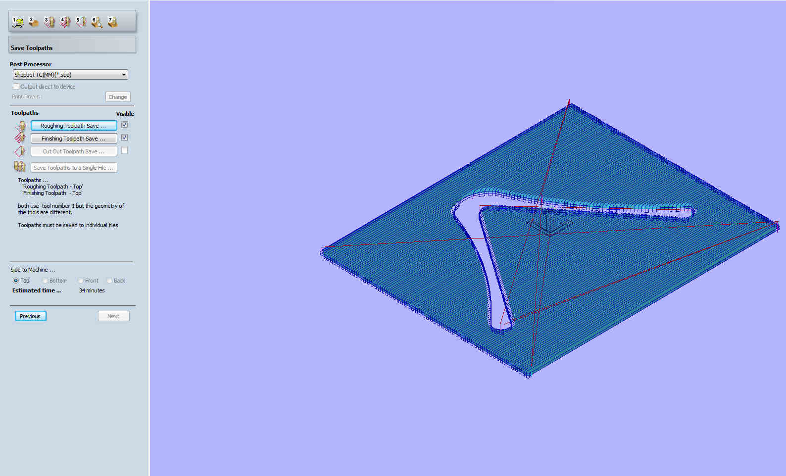 Toolpath Preview
Group Assignment: Making the test coupons
Before laying our hands on jute and epoxy we decided to make test coupons.
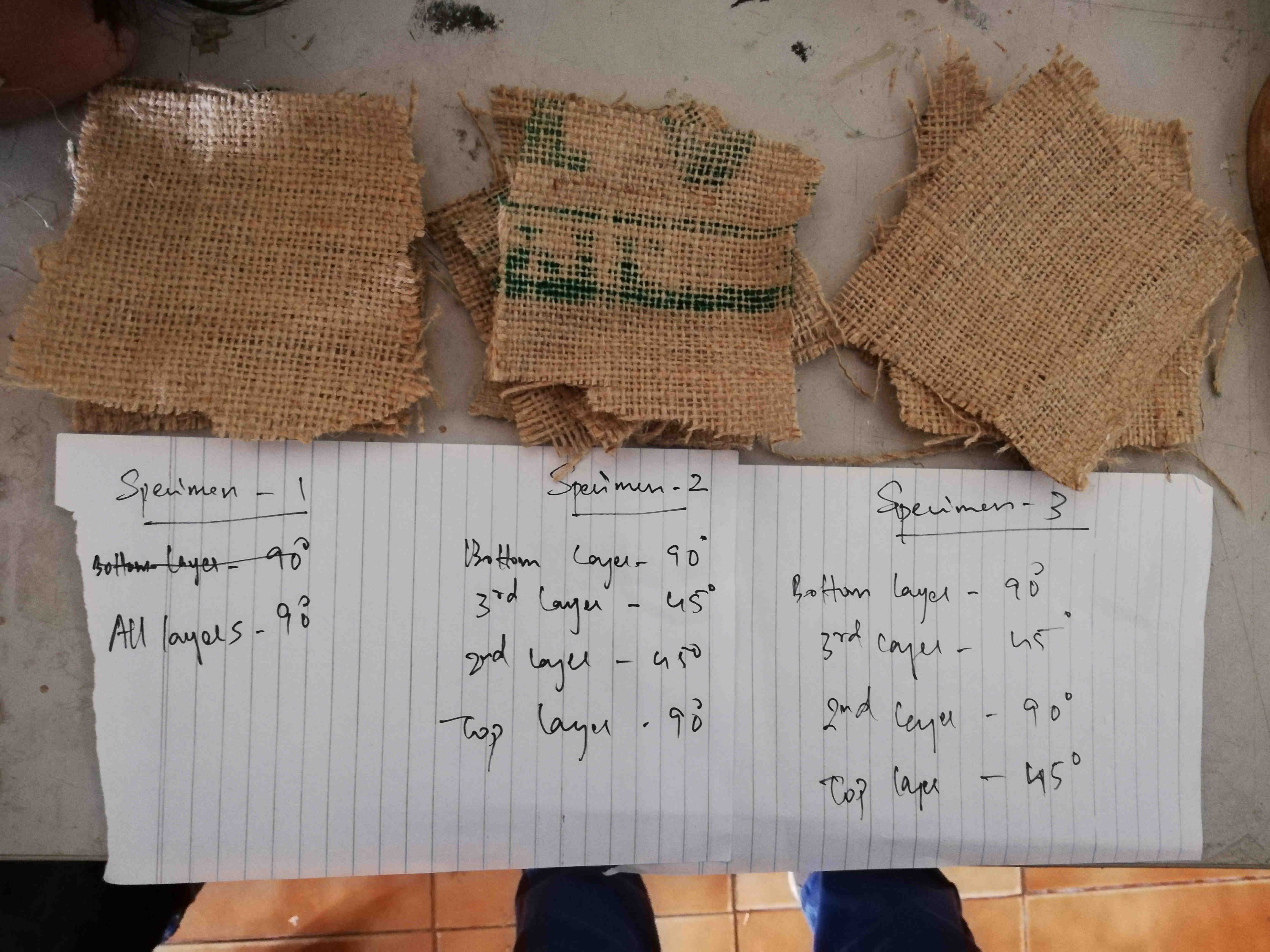 3 sets of layers of burlap were cut to the size of 10cmX10cm. In the first set all 4 layers of burlap are arranged in 90 degrees. In the second set top and bottom were kept at 90deg and middle layers at 45 deg. In the third set all layers were stacked alternatively with different orientation.
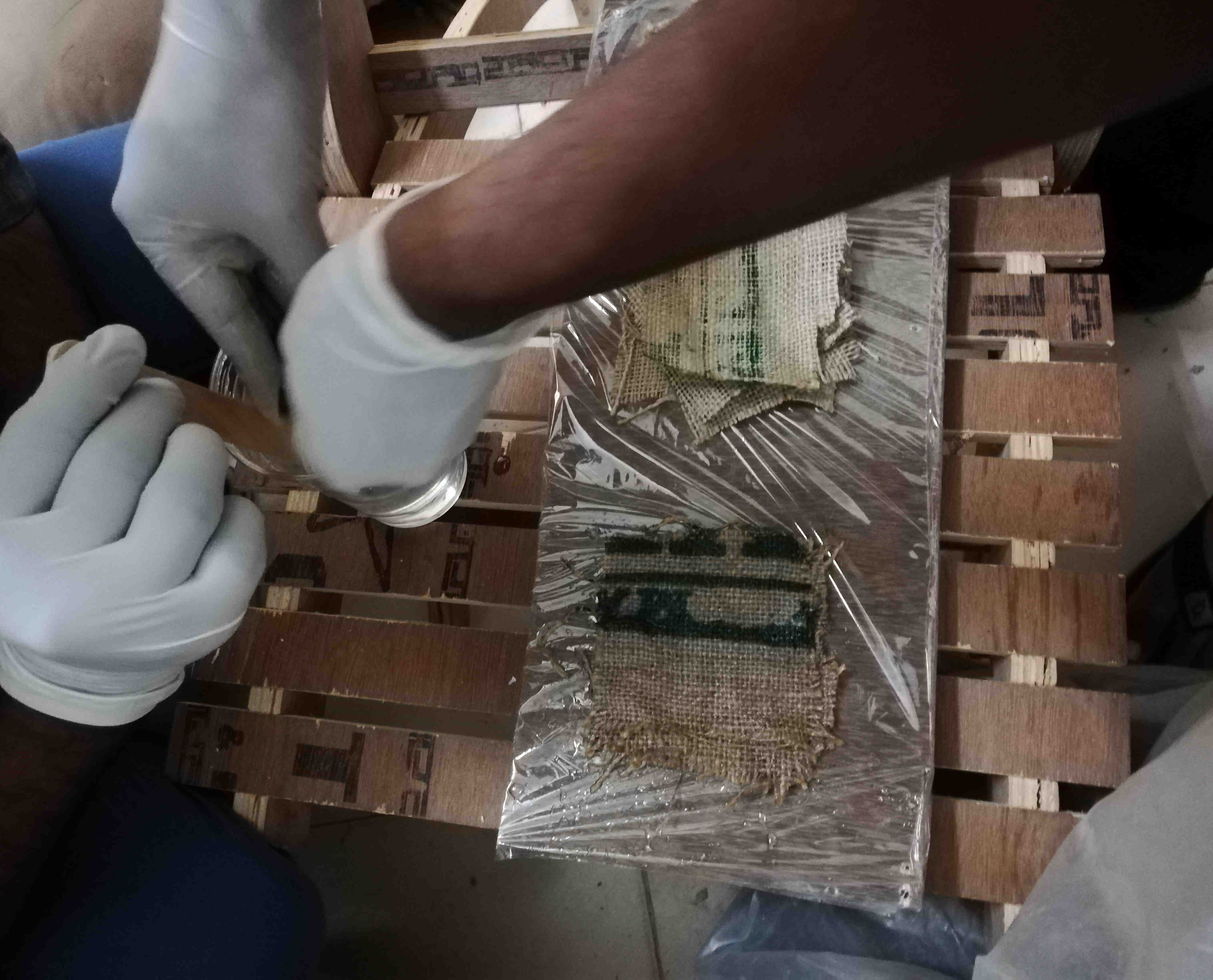
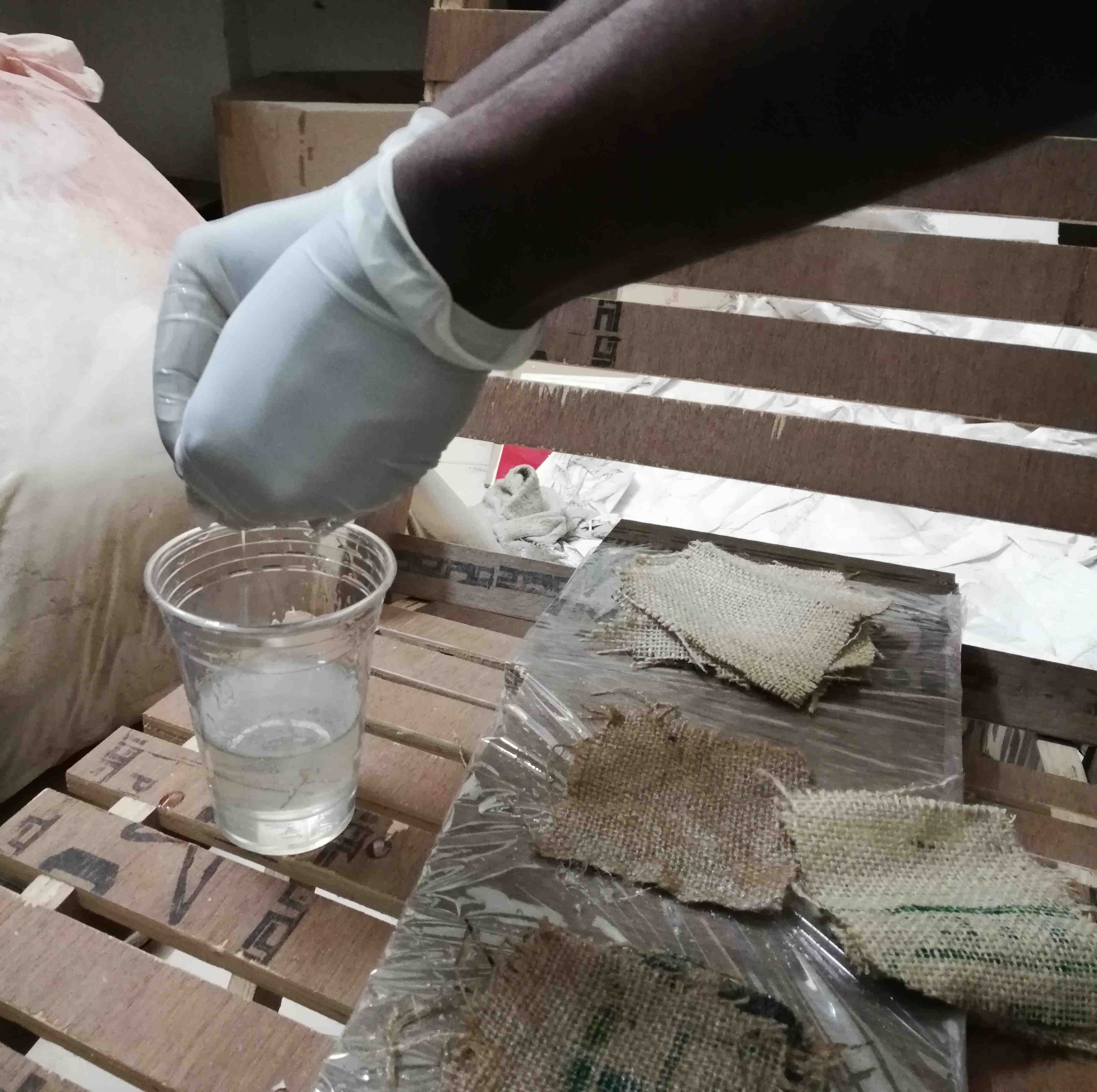 Epoxy was taken in measured quantity by mixing in different parts (Part A and B). Each layer of burlap was soaked and squeezed off lightly to wet the burlap with epoxy layer. Layers were stacked one over the other.
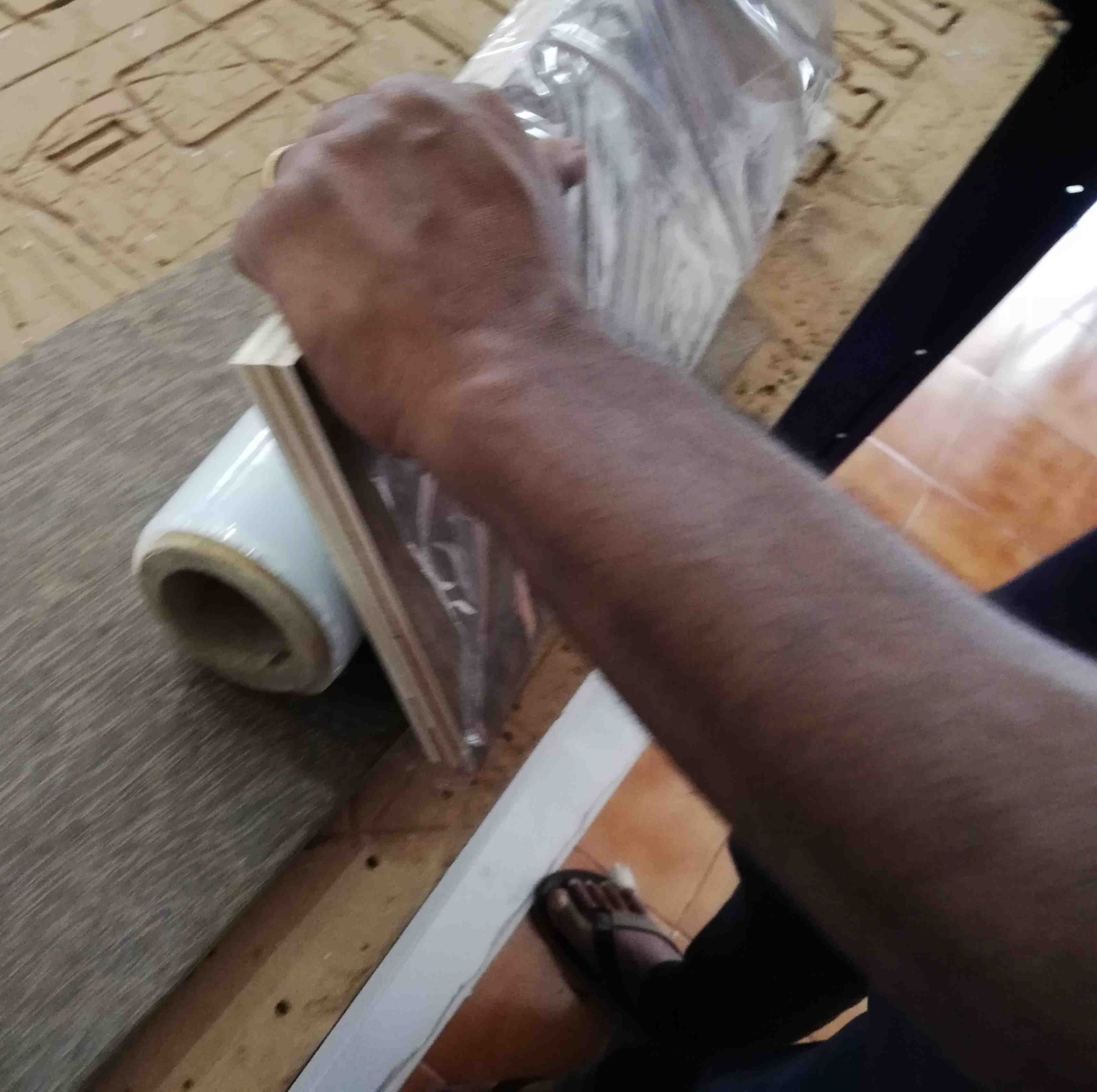 The stacked layers are to kept between two plywood boards. On one board the board is wrapped with food wrap plastic tightly to prevent adhesion of the pressed test coupon to the plywood board.
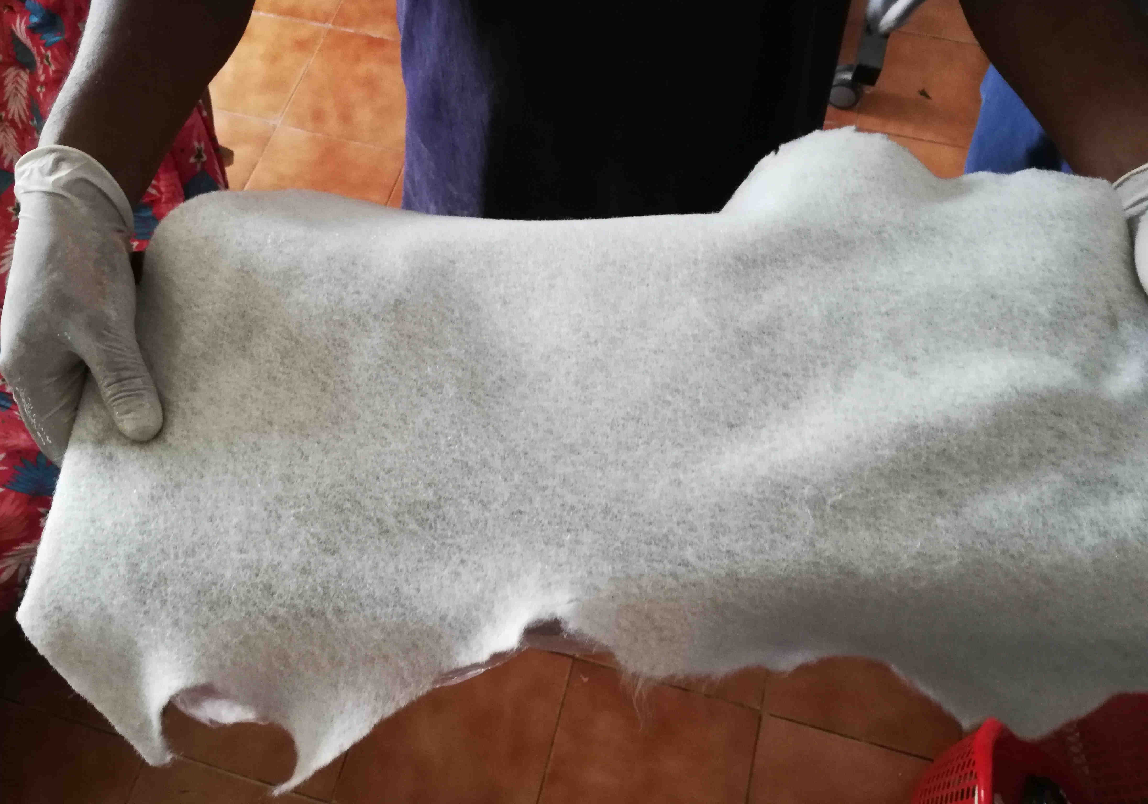 A breather cloth was kept over another plywood board to absorb excess epoxy.
 The layered coupons wet with epoxy is laid over the board wrapped with plastic layer
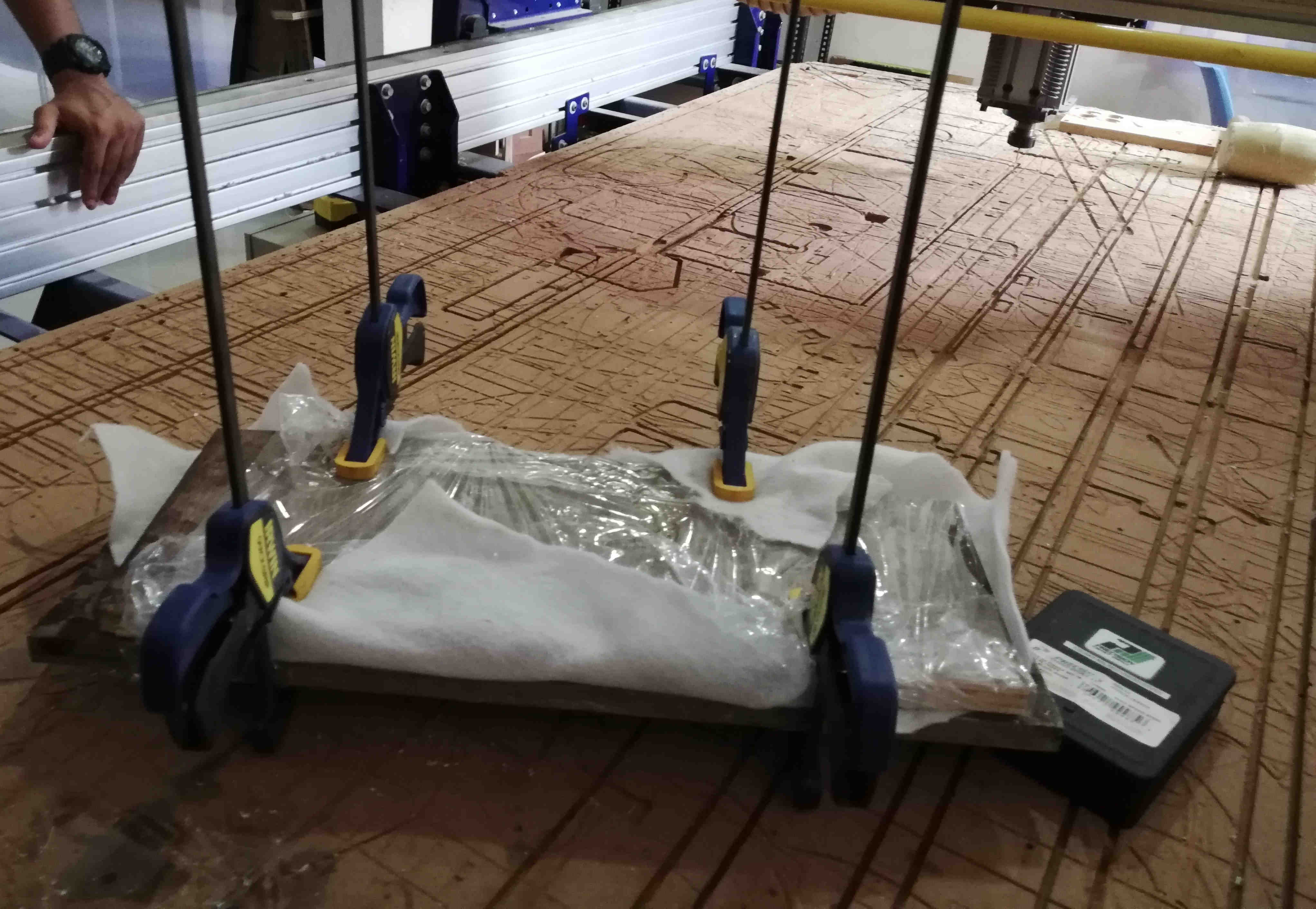 The coupons are kept pressed using press and kept for a day to cure
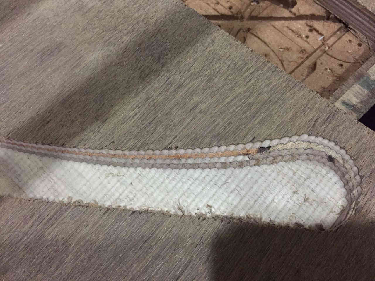
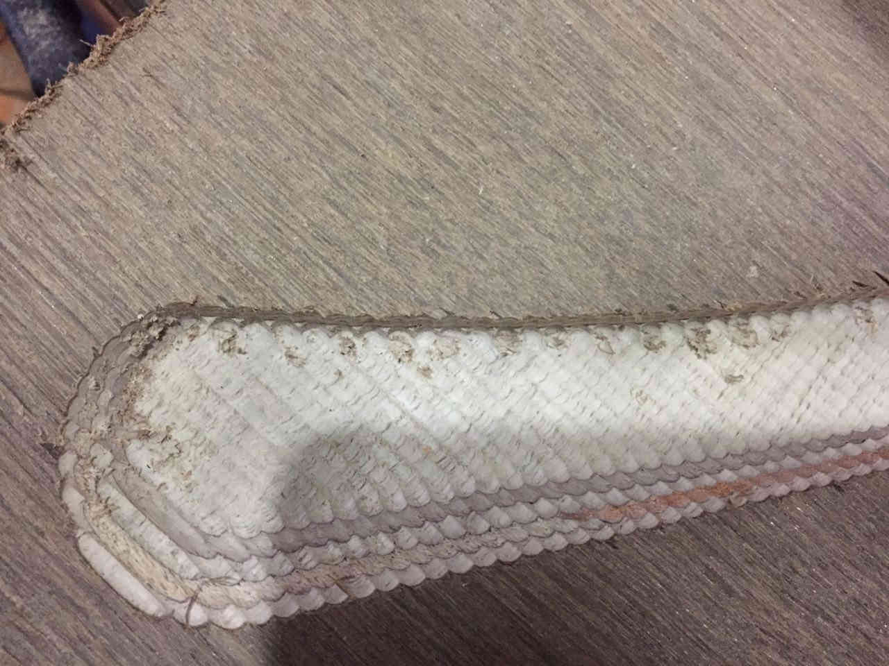
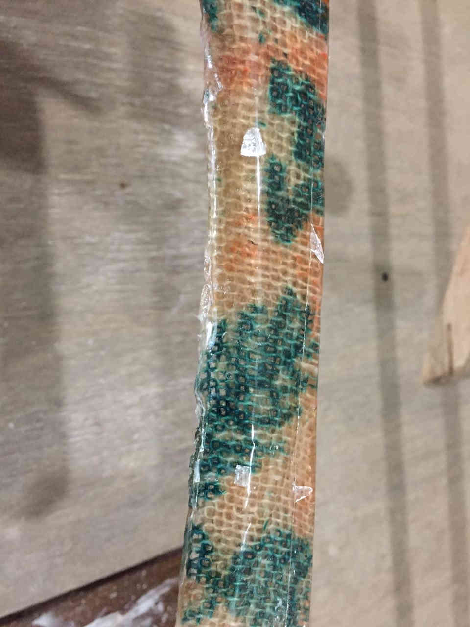
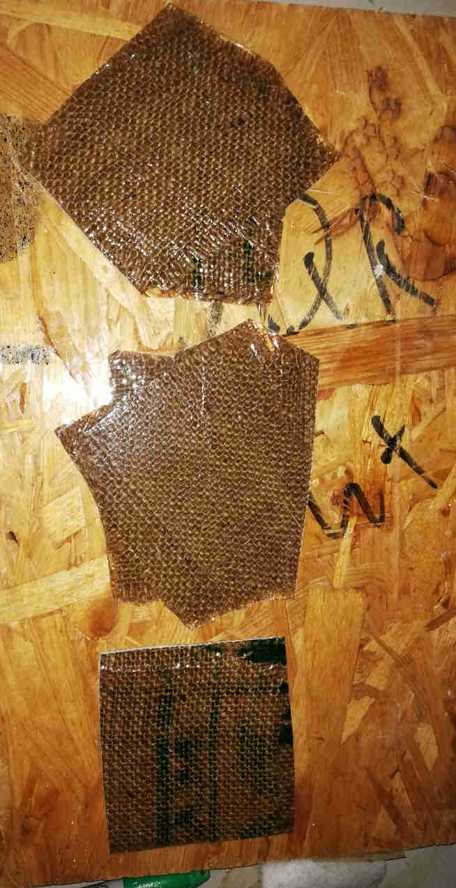 Coupons after curing. Clearly the burlap material with layers oriented alternatively at 45 deg and 90 deg was stronger in bending and tension.
Milling and preparing the mould
After setting the tool paths the job was completed in shopbot
 The edges came out good only thing that the stepover in the machine cutting could have been kept less for smoother finish in the edges.
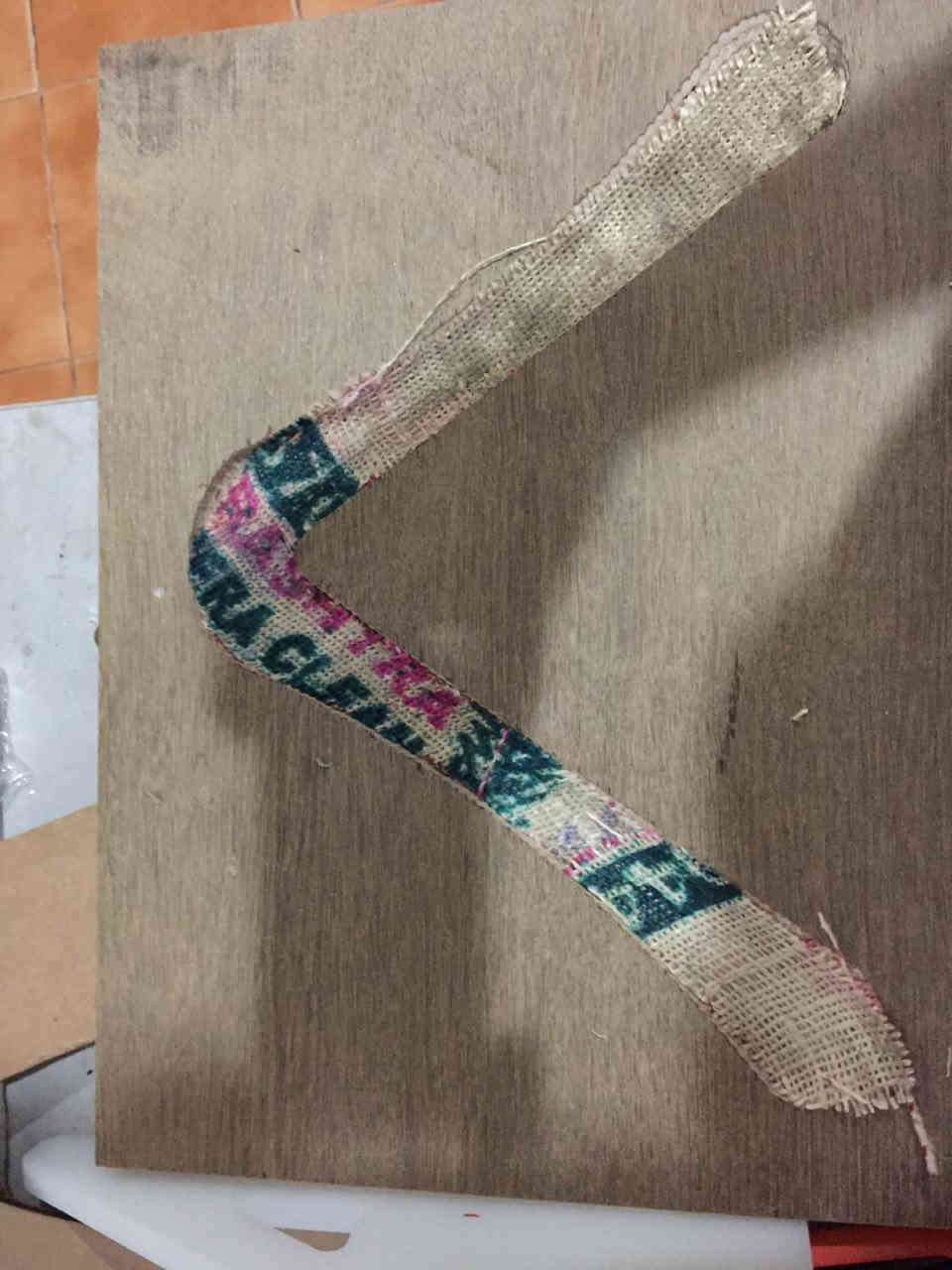
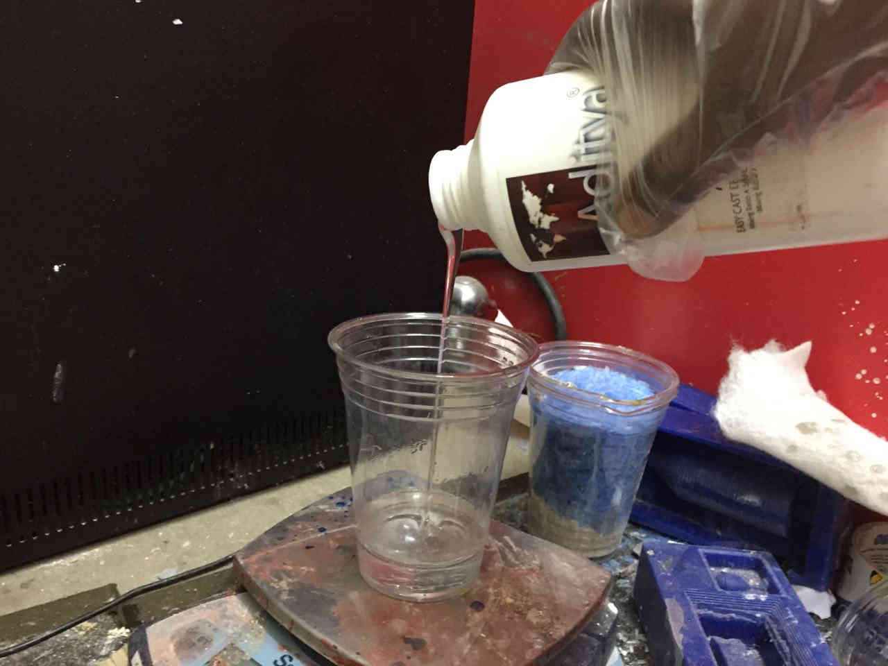
The jute fabric was cut to the shape of the mould. Since we didn’t had the laser machine, the only option was to cut it manually. Epoxy in right proportions are mixed in a glass and weighed.
The edges came out good only thing that the stepover in the machine cutting could have been kept less for smoother finish in the edges.
The jute fabric was cut to the shape of the mould. Since we didn’t had the laser machine, the only option was to cut it manually. Epoxy in right proportions are mixed in a glass and weighed.
 Before pouring epoxy the insides of the board were fixed with cellotape for ensuring non adhesion of the epoxy with the surface. Also a layer of vaseline was pasted on the inside of the mould.
The jute is dipped in epoxy and laid onto the surface. Here we have used it only on one layer.
Before pouring epoxy the insides of the board were fixed with cellotape for ensuring non adhesion of the epoxy with the surface. Also a layer of vaseline was pasted on the inside of the mould.
The jute is dipped in epoxy and laid onto the surface. Here we have used it only on one layer.
 After filling the remaining portion with epoxy. The inside part of the mould was covered with adhesive tape to prevent adhesion of the burlap layer to the insides of the mould.Jute in single layer is used at the trailing edge and 3 small pieces were laid in layers in the leading edge to make it heavier on that side.
 A breathable cloth was alaid over the mould to absorb excess epoxy.Polythene plastic sheet was then tightly fixed over the material to protect it. It was ensured that air bubbles are not caught inside mould surface. Our vaccum bags weren’t functional so we had to do it manually. The surrounding part of the mould were covered with cellotape for allowing easier removal of the boomerang after setting. After this the entire assembly was kept pressed under weight using dust sacks in the lab so as to maintain the pressure on the mould.
Two part mold was not used as the boomerang design was with flat bottom and sufficient compression and confinement of the fibres was ensured by overlaying with a heavy sack.
A breathable cloth was alaid over the mould to absorb excess epoxy.Polythene plastic sheet was then tightly fixed over the material to protect it. It was ensured that air bubbles are not caught inside mould surface. Our vaccum bags weren’t functional so we had to do it manually. The surrounding part of the mould were covered with cellotape for allowing easier removal of the boomerang after setting. After this the entire assembly was kept pressed under weight using dust sacks in the lab so as to maintain the pressure on the mould.
Two part mold was not used as the boomerang design was with flat bottom and sufficient compression and confinement of the fibres was ensured by overlaying with a heavy sack.
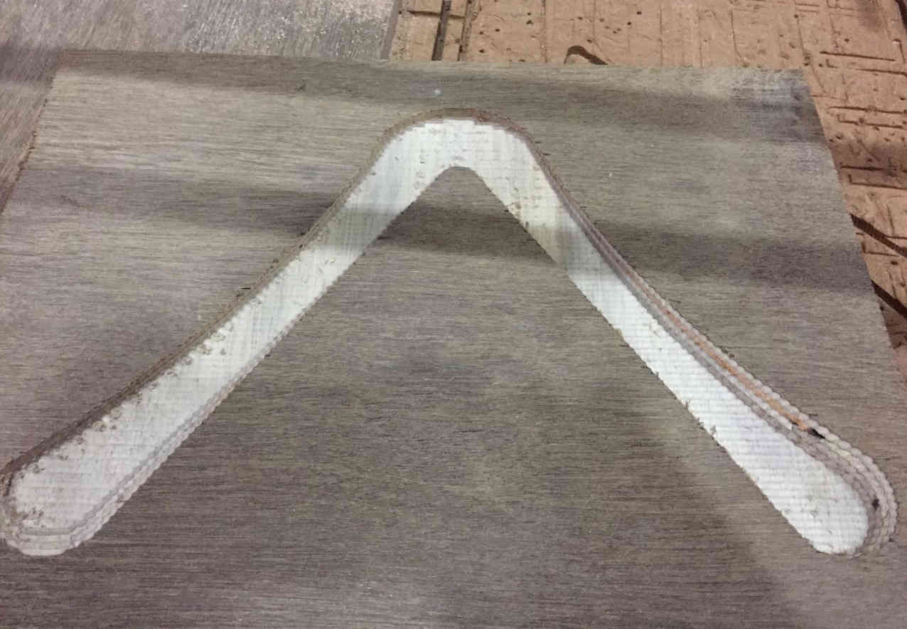
 The cast was removed from the mould after curing it for 10 hours.
 The edges didn’t come finish as i had expected. But still it was pretty a decent effort.
 The edges are to be trimmed and finished off for a smoother edge.
As I expected the boomerang didn’t return after I threw.May be it could be the issue with design or it could be the way I did in its preparation. I am yet to figure out. Overall it was a good experience.