3. Computer Aided design
This week we started with various drafting softwares.
Raster and Vector
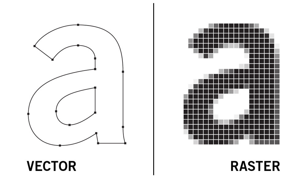
A raster graphics or bit map image is type of media format in computers where an image is represented by array of pixels in a rectangular grid. Each pixel’s colour is reperesented by bits. The images are represented in JPG,PNG,GIF format. A vector graphics is one in which the images are represented using 2D points. Lines or curves join these points to make images. Other properties like stroke color, type of curve, thickness etc are represented in the vector drawings. Formats like SVG,EPS and PDF are examples for vector image formats.
 Credits :https://www.ratermanis.com/blog/2017/12/28/vector-vs-raster
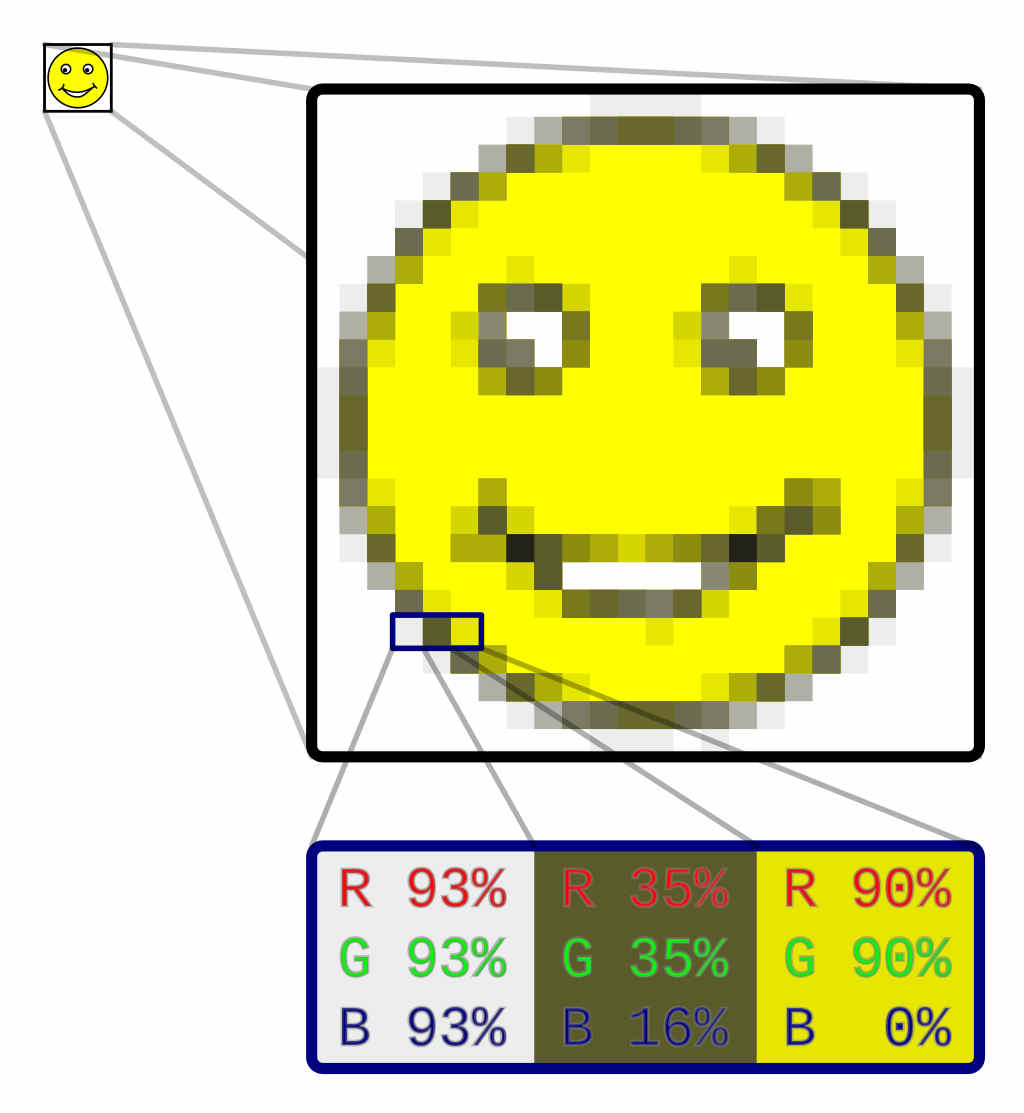 Each pixel is having bit information which is the combination of Red, Green and Blue.
Credits: https://en.wikipedia.org/wiki/Raster_graphics#/media/File:Rgb-raster-image.svg
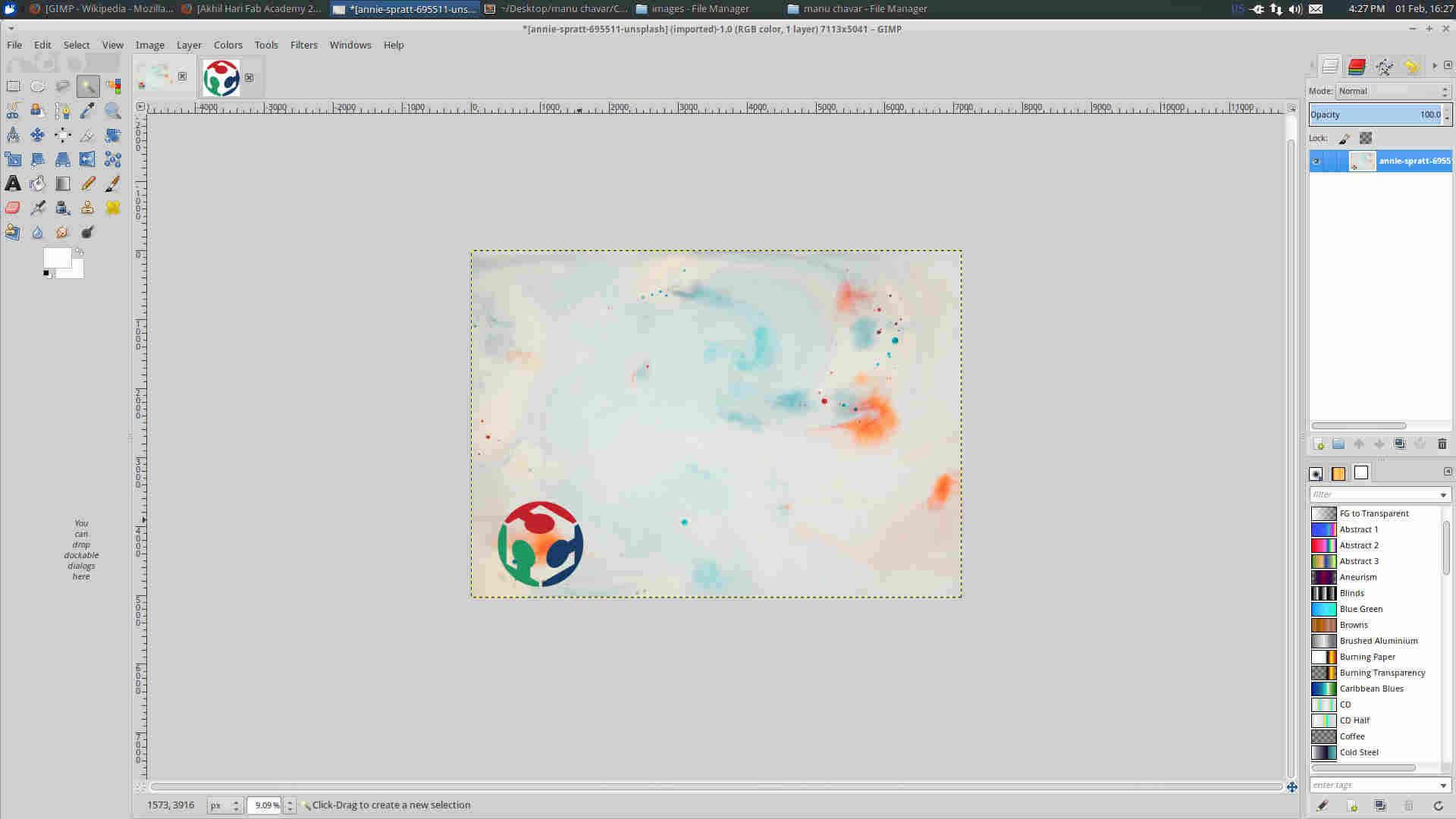
GIMP (GNU Image Manipulation Program)
GIMP is a free and opensource raster based image editing software. Images can be modified and edited by creating layers and editing them.
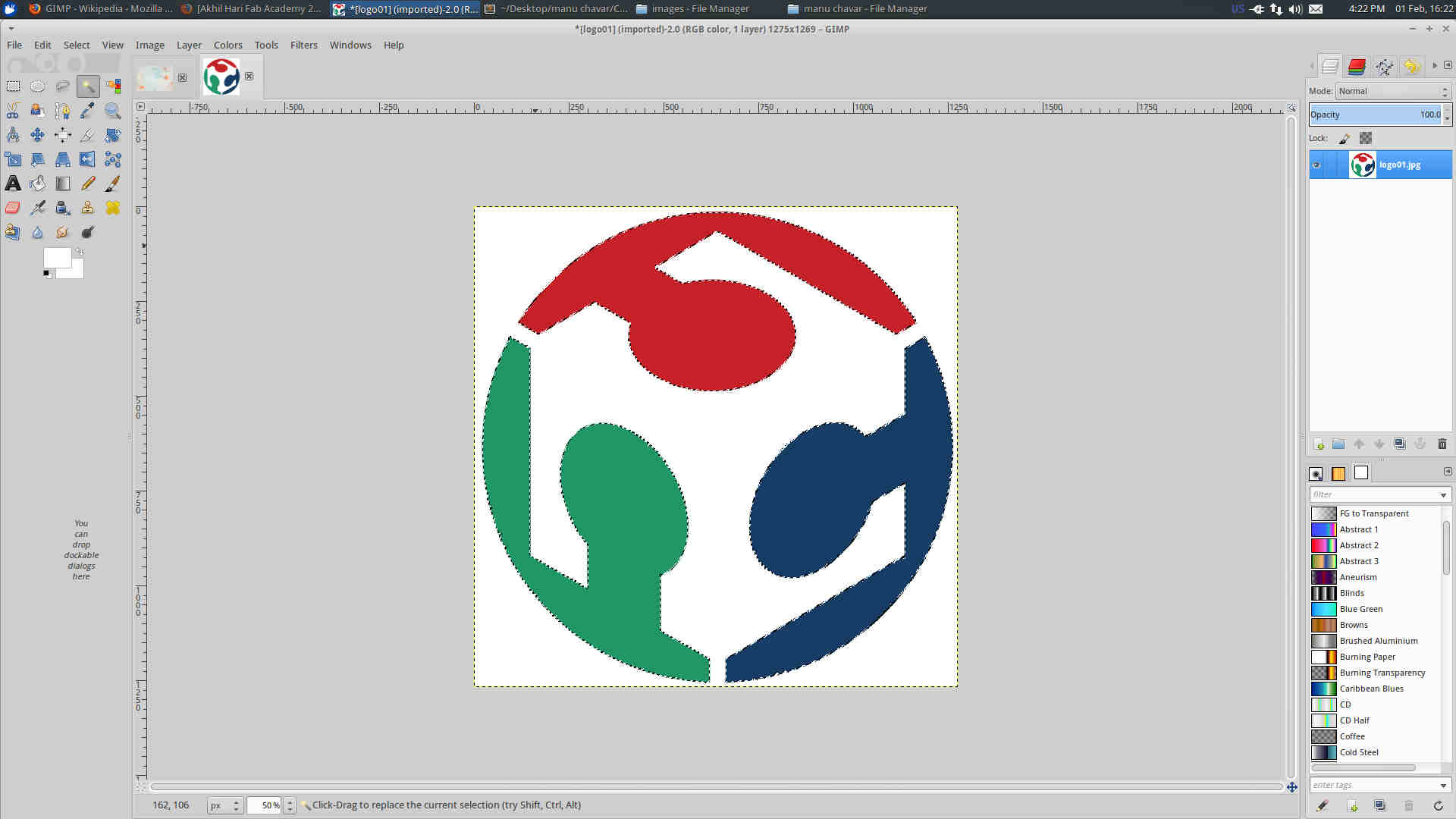 The logo can be selected using Fuzzy select tool
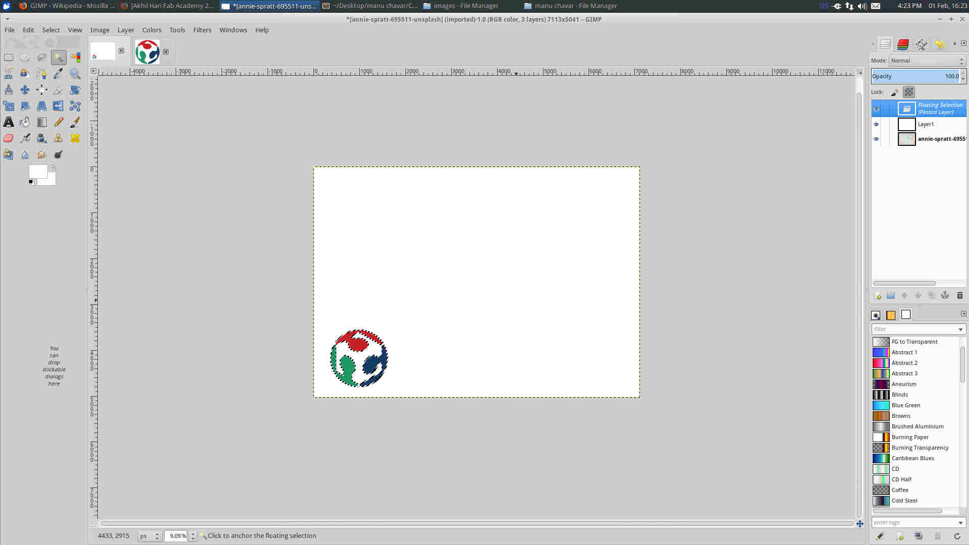 New layer added and the logo pasted upon it
 Copying the selected logo
File here
Inkscape
Inkscape is an opensource vector based image processing software.
One of the uses of inkscape is that you can convert a raster image to a vector one. trace bit map from the path.
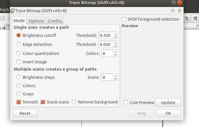 Various scanning options
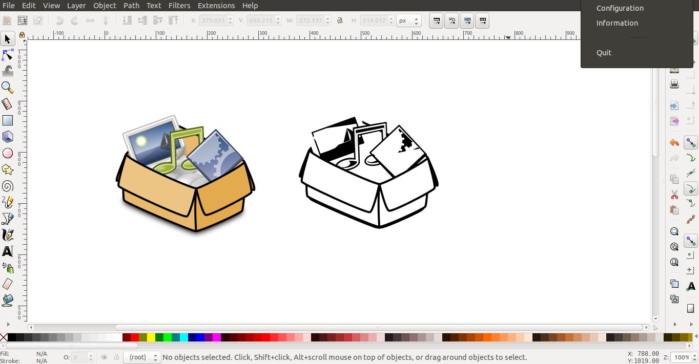 Scanned picture
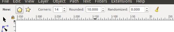
Another option is that we can create interesting polygons.
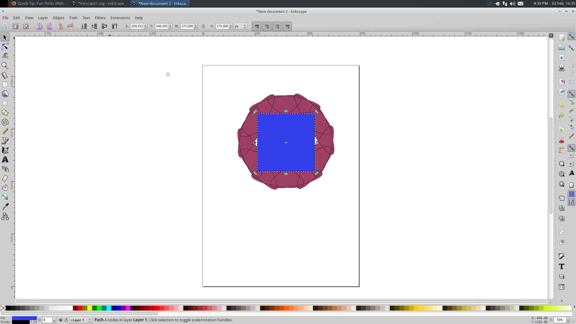 Two poygons placed over each other.
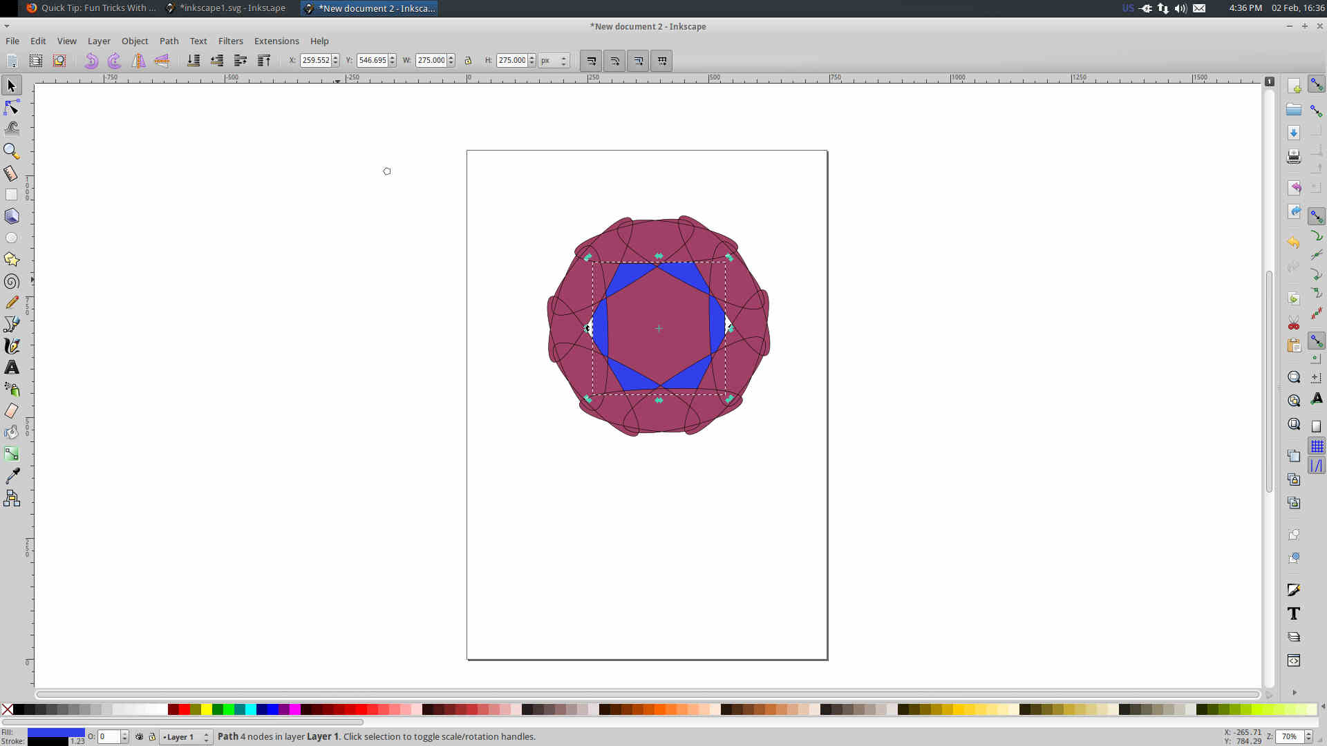 The
The Difference tab under path can yield interesting shapes. The blue square was placed under by Move Selection to layer below in the Layer tab.
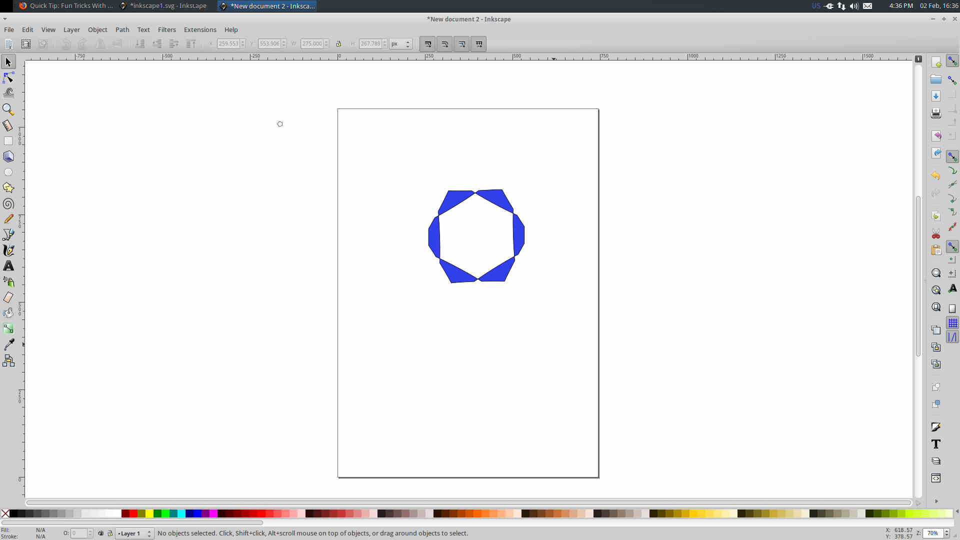 This time with
 Intersection in the Layer tab.
File here
3D-Parametric modelling
Parametric modelling enables us to use computer to create models that can simulate almost real world like geometry and other functional attributes. Parametric models are based on mathematical equations.
There are two parametric representations
1) Constructive Solid Geometry (CSG)
Development of basic primitive models like sphere, cylinder, cube etc. Operations like extrude,boolean etc. are performed to alter/ build the model.
2) Boundary Representation (BR)
Model is built my surfaces. These surfaces are inturn made by connecting spatial points. Finite Element based softwares mainly work this way.
So many softwares are used for example Solid Works, Fusion 360, FreeCAD, Oneshape etc.
FreeCAD
In this one week I tried my hands on FreeCAD. FreeCAD is an opensource parametric modelling software. Ver .17 was used.
FreeCAD necessarily has workbenches. Workbenches can be described as a set of tools designed specific for sepererate modelling applications. FEM ,Part , Part Design, Sketcher etc.. are some of the work benches.
Constraint Sketching- Unlike traditional drafting the models are first drafted unconstrained. These can be extruded, rotated or scaled according to the constraint conditions. I started by working in Sketcher workbench.
I started by making a circle in the part workbench and extruded it to get the required thickness. The groove of this pattern was made by Holecommand in `part design’ . In the sketcher workbench various restraints can be used both geometrical as well as dimensional.
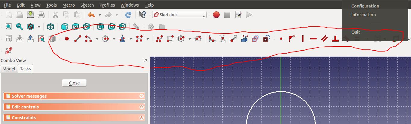 Various restraints in the Sketcher workbench
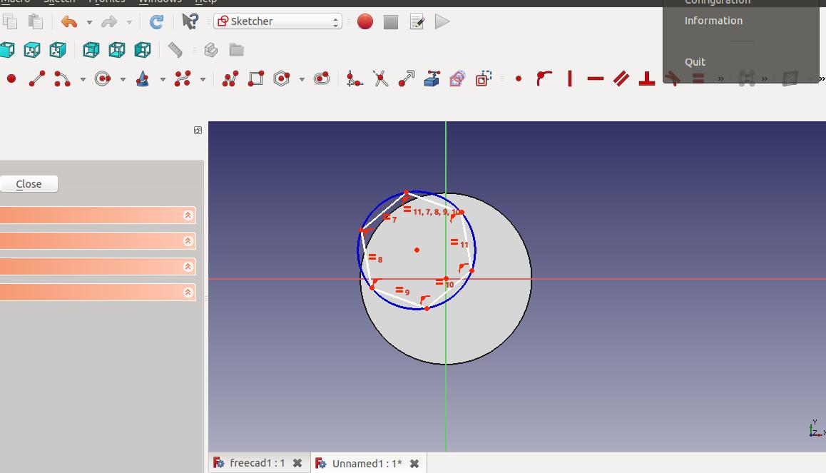 Restraints shown in red as inside angles of the polygon
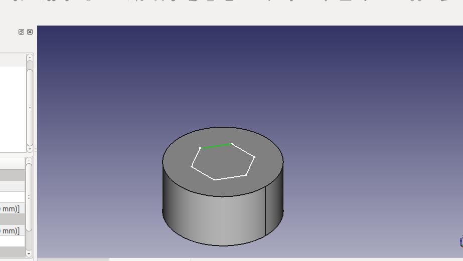 Centre of the polygon aligned with the centre of the extruded solid.
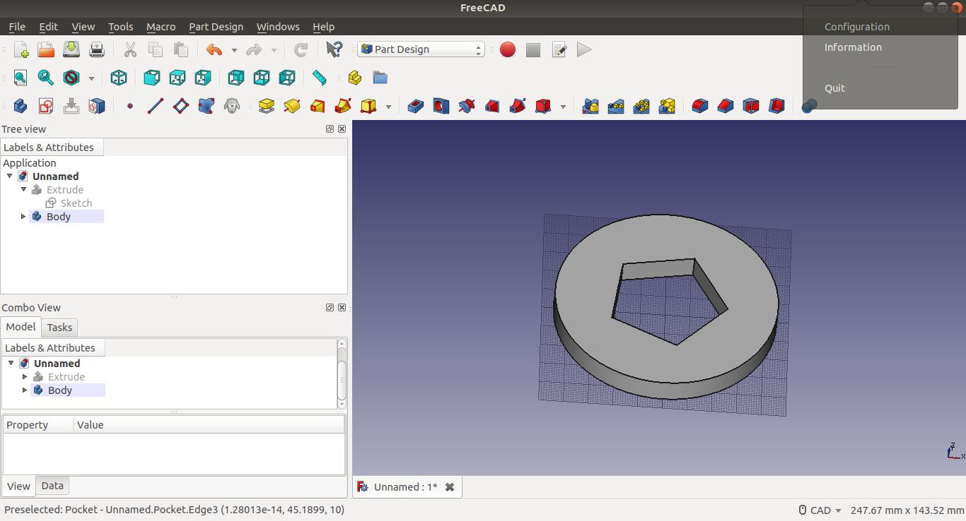 Hole extruded using
 hole in the part design
File here
Though I started with FreeCAD I understood only in the later weeks that the Fusion 360 suits me better. The dating part was not complete in this week. Frankly I was too slow to experiment with different softwares in a week. But after selecting Fusion 360, I got acquanited with it over the time and during the final project week the tool came so handy that I could use it without external help. The links to the other week’s work in CAD design in Fusion 360 is below.
(This part was documented during the evaluation)
Week 4-Press Fit Design
Week 6- 3D printing CAD Design
References
- [Parametric Modelling] (https://www.designtechsys.com/articles/parametric-modelling)
- FreeCAD WIKI