11. Input devices
This week was based on designing a microcontroller read the input by using a sensor and the Group Assignment was to probe an input device’s analog levels and digital signals
Through the week
The second plan of my final project was to make a smart slide changer which is capable of changing slide by shaking it by using an accelerometer or a gyroscope attached with a pointing laser source
But my knowledge in electronics was poor I managed to do a simple proximity circuit on input week to study the basics
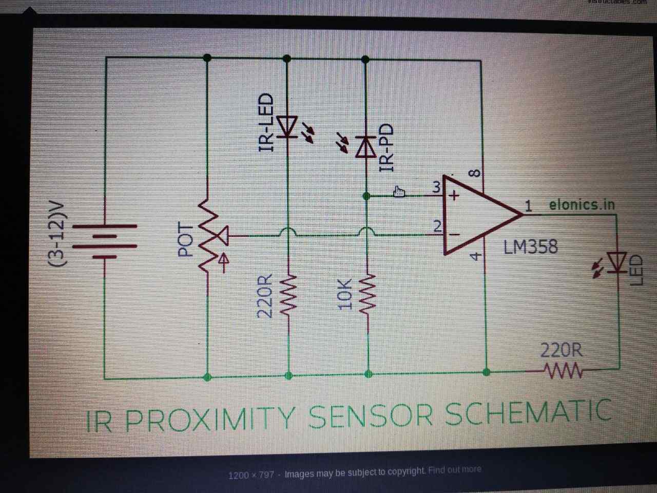
For that I referred through various circuits available in the internet and estimated to do a simple proximity circuit with photodiode and IR led with LM358RC.
Components Identified
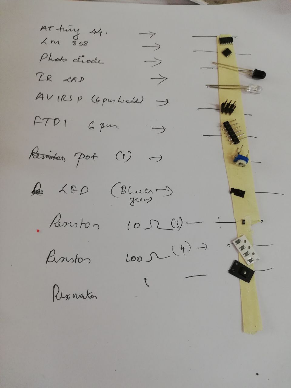
The basic Components identified for completing the circuit was
1.Photo diode
2.IR led
3.LM 358rc
4.100k and 10 Resistors
5.ATTINY 44
6.POT Resistors
7.AVIRSP 6 PIN header
8.FTDI header
9.20mghz Resonance
10.LED
Basic idea
The basic idea was to make connect an IR led to the positive terminal by giving a 100k resistance to follow by connecting it to a Photodiode and connecting it to the potentiometer(POT) as the reference voltage and then to compare the difference produced by using a comparator ie.LM358rc and connected to the negative terminal of the circuit.
Works Done
After estimating the components I designed the Circuit using AUTODESK EAGLE.
1.On the first sheet I draw the basic connections from ATTINY 44 to ftdi and avrisp headers and the basic circuit on the second sheet.
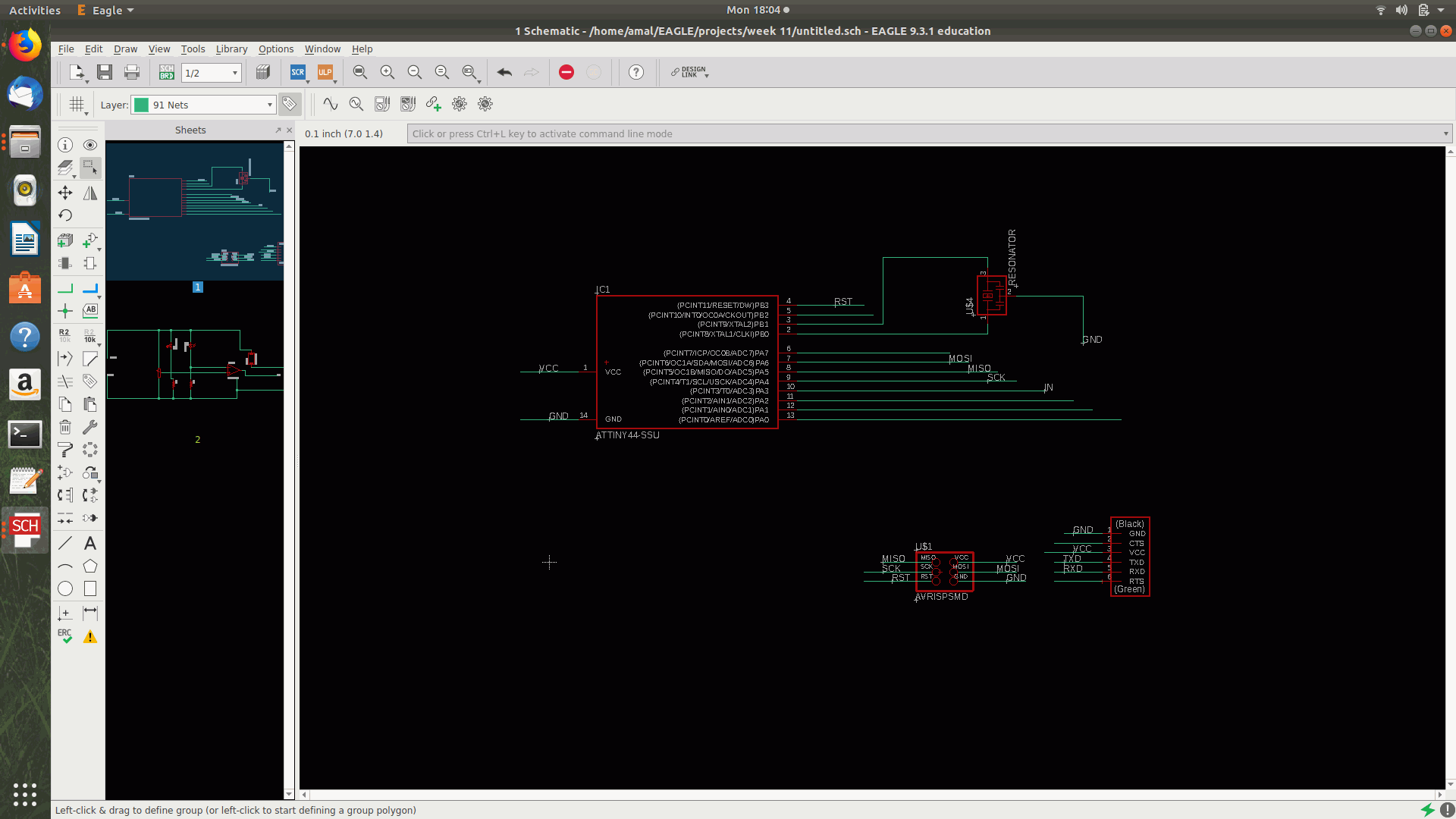
2.The POT resistor pad was missing so i managed to download it and add to the library
since the available pad was too small to fit through hole component and the basic idea for using a component outside fab library was to get a maximum big sized pad.
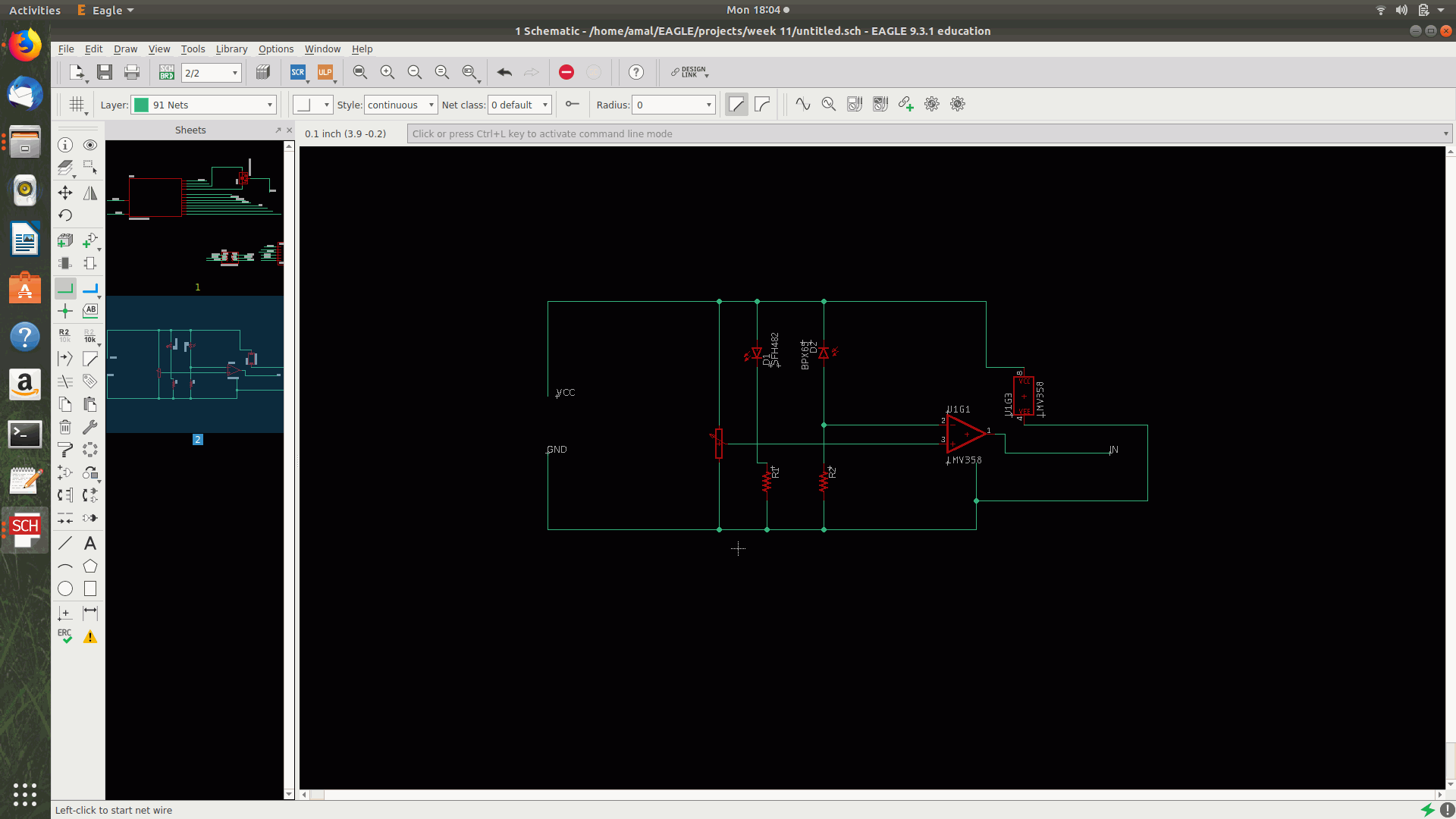
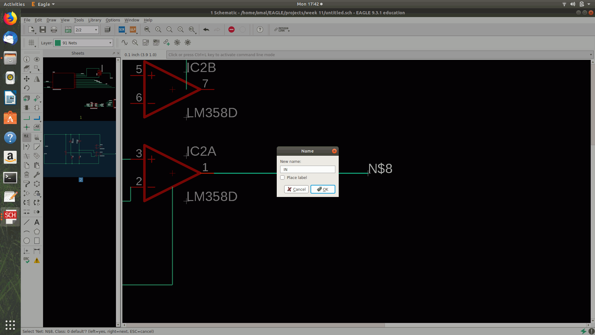
3.Then COnnected the IN pin and by that I Connected the circuits between the 1st sheet and the second sheet by making an IN pin

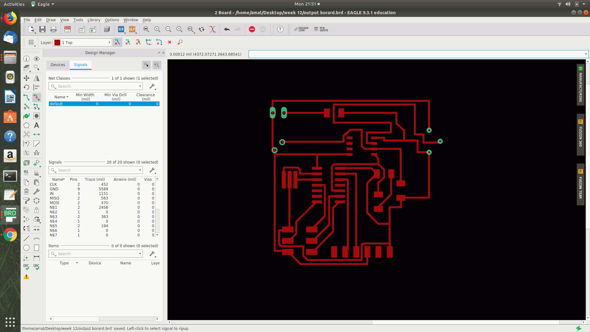
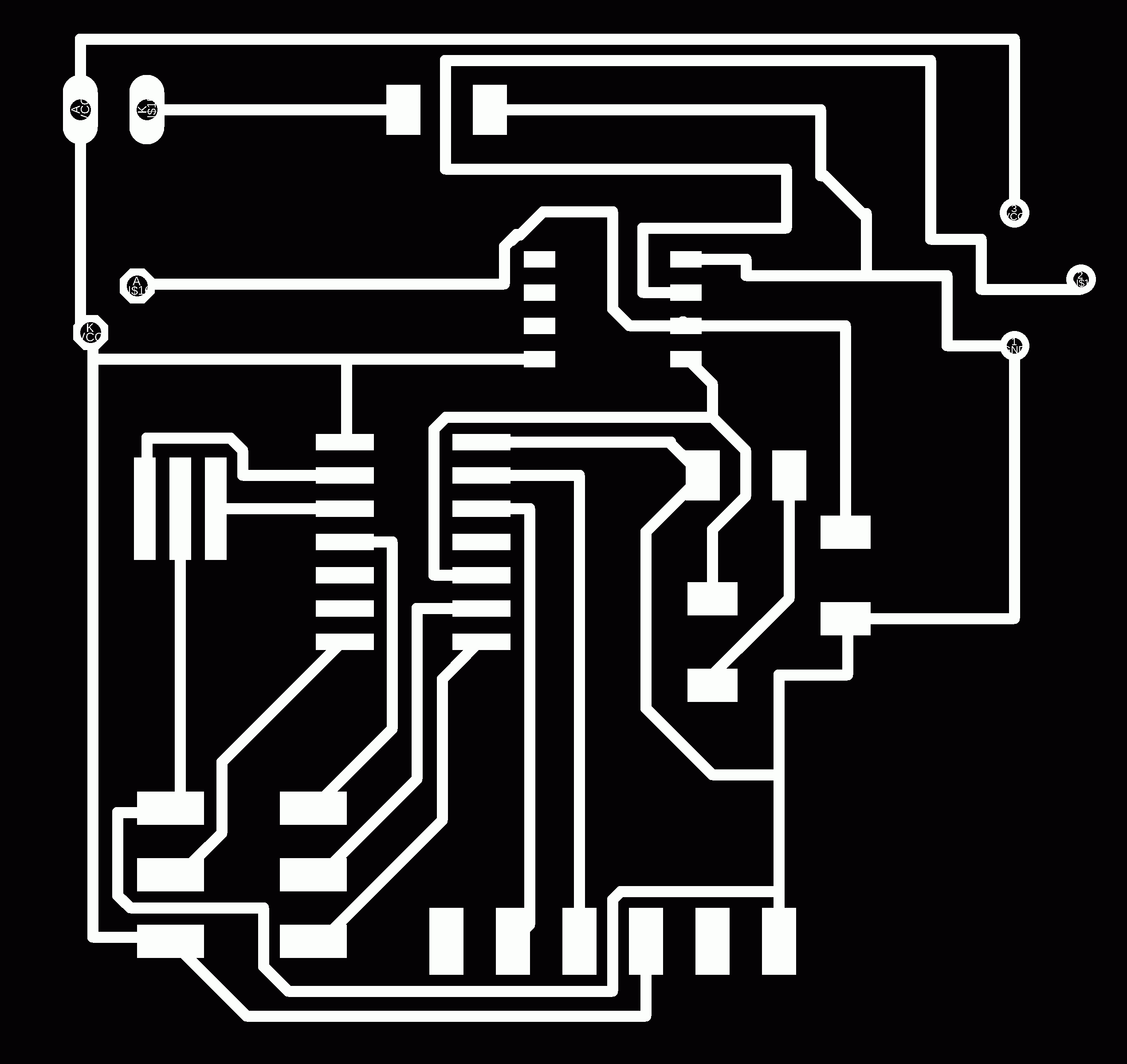
4.After getting a perfect route I managed to export the file as Png by making the uplayers
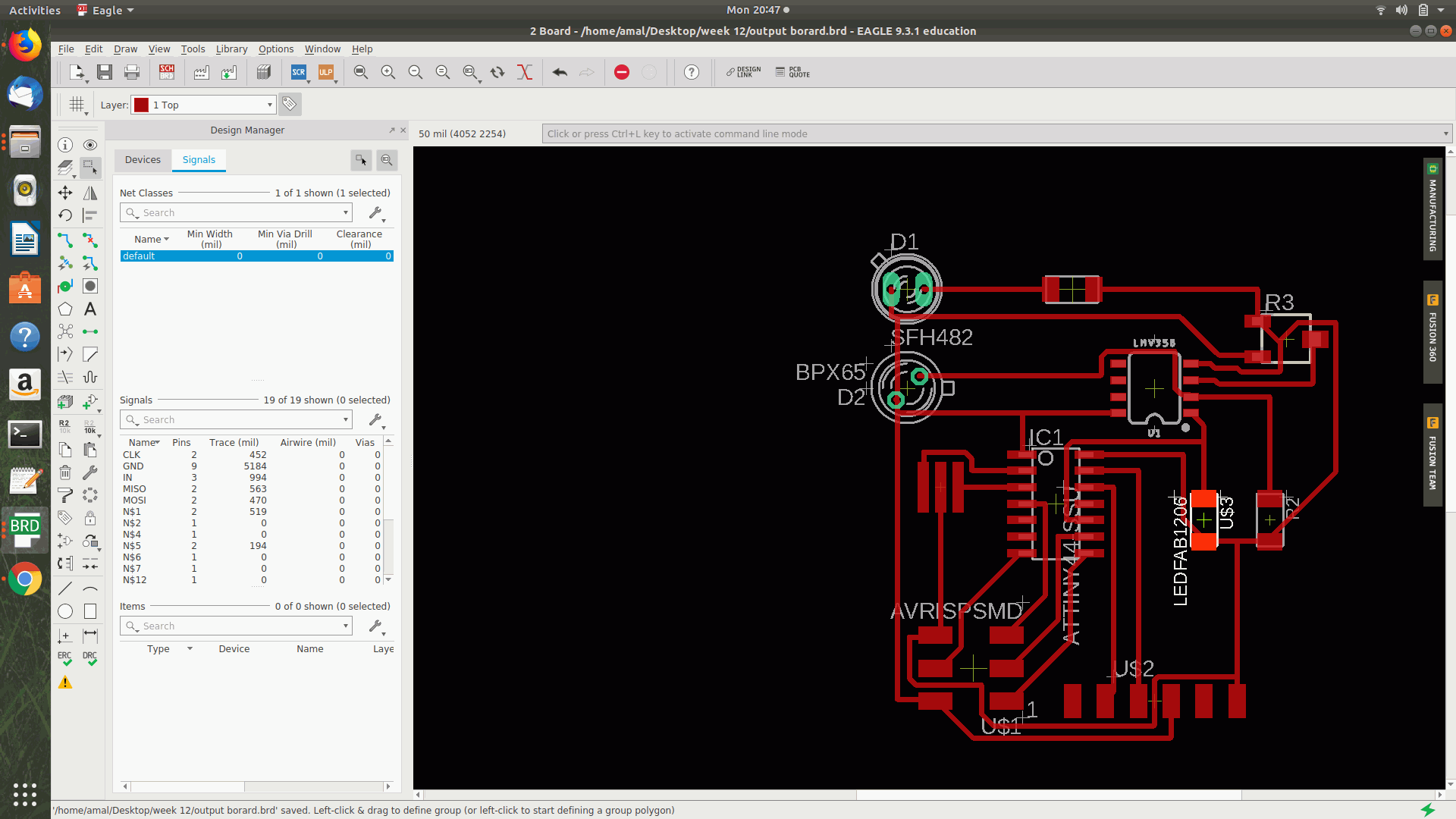 and bottom layers visible and later on turned off all the layers for getting the outside board.

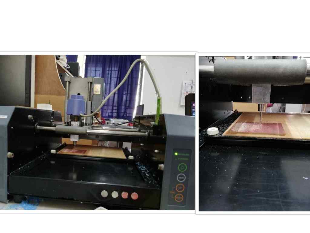
5.After that I milled the circuit by following the sequence studied on the electronic production week.
Then I managed to export it to the gimp editor and cropped the image without losing its actual size.
.
followed by modella for the milling process.
6.After getting the components from the library I manged to solder it
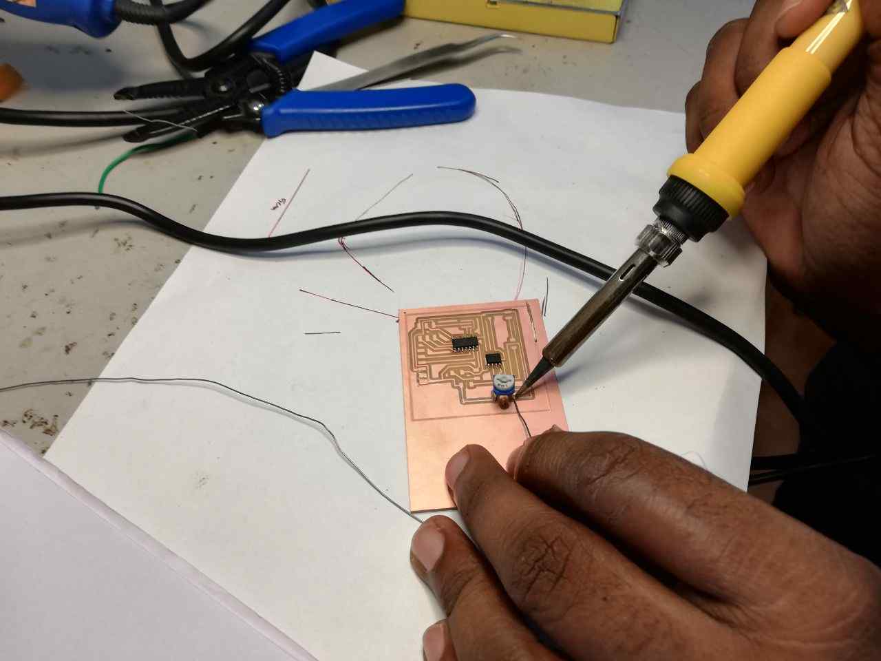
7.The main issuie I faced with while soldering was to fix the IR LED and Photodiode and POT resistor was fo fit leg to the pads.
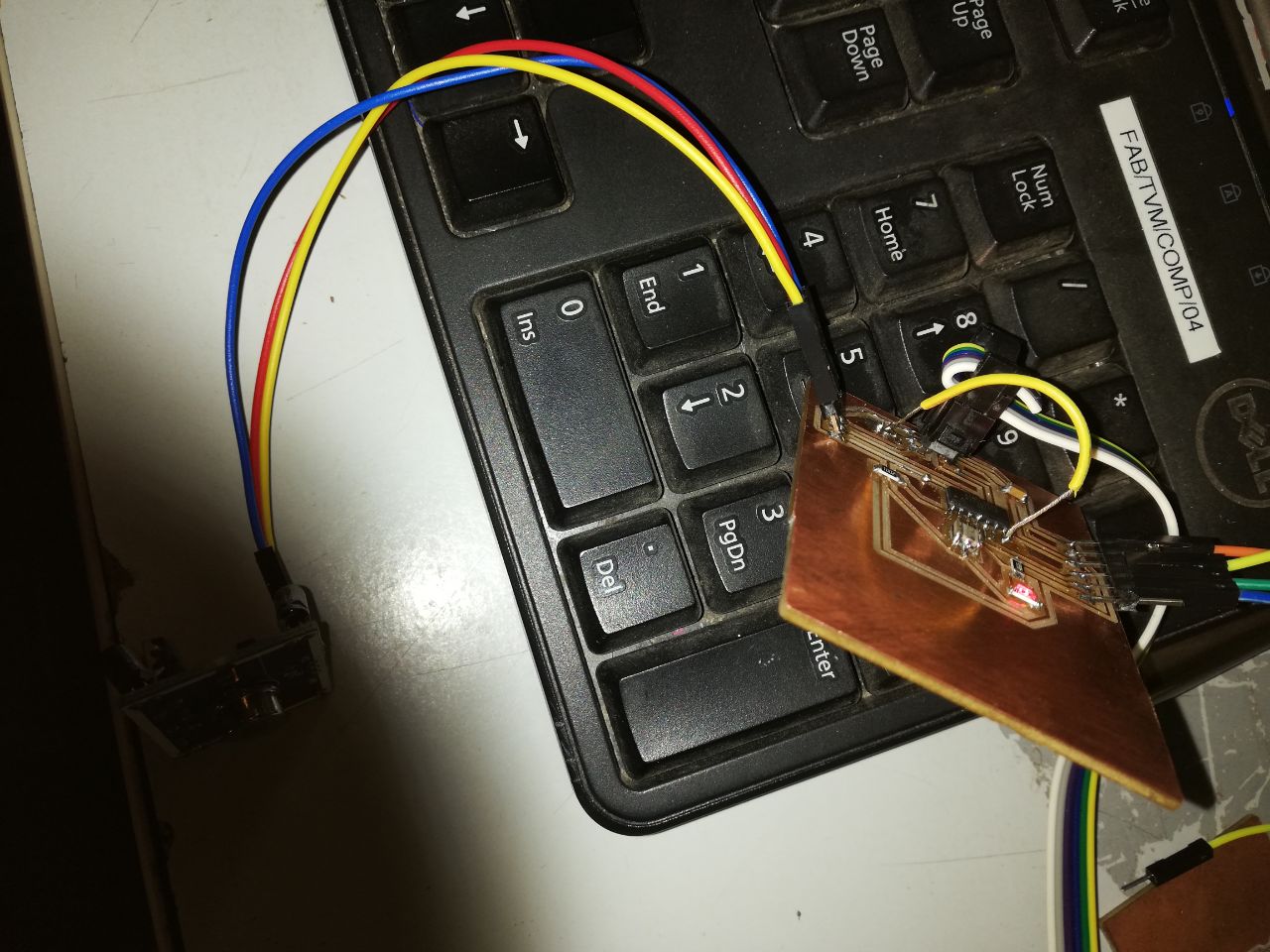
8.After soldering all the components I manged to program it by using arduino ide and connected to the programmer which was made during the electronics production week through AVIRSP headder.
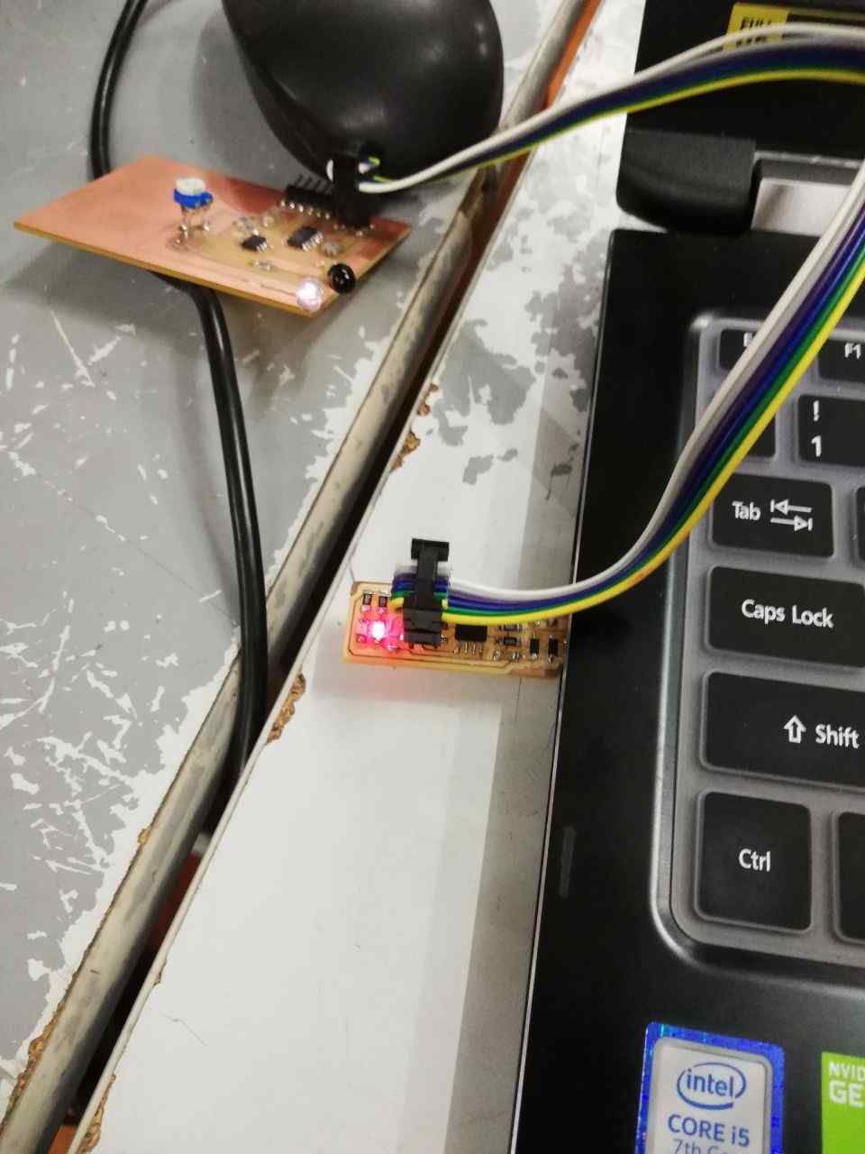 9.For that I selected the ATTINY 44,AVIRSp, etc for burning the boot loader

10.But the authentication showned error and the signature does not match
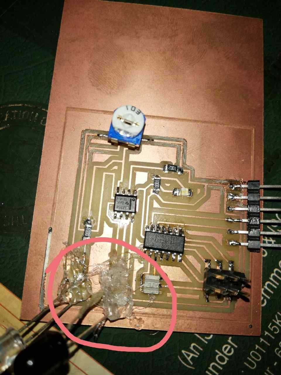
11.While trying to resolve the issue it was found that the IR LED has lost the traces and I managed to resolder the leg and after that i poured some glue by using glue gun to it for safety.
Then I tried to mill another board.But this time I planned to change the borad by using a PIR Sensor bu UART Connection. For that I used the following Steps.
PIR
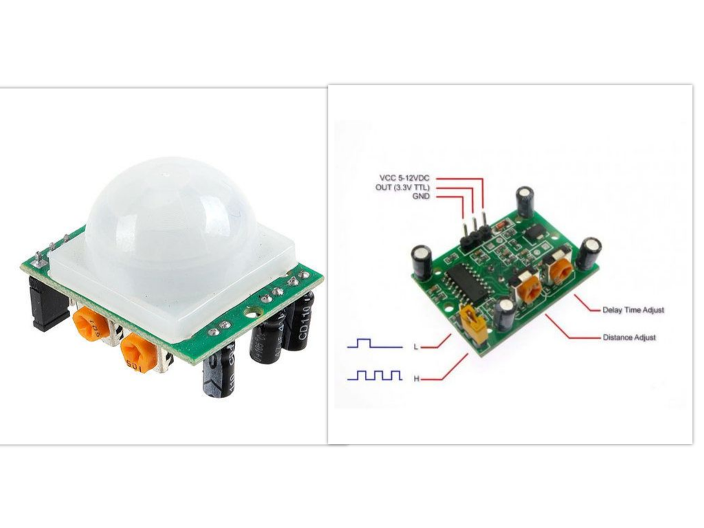
A passive infrared sensor (PIR sensor) is an electronic sensor that measures infrared (IR) light radiating from objects in its field of view. They are most often used in PIR-based motion detectors.
Things I done
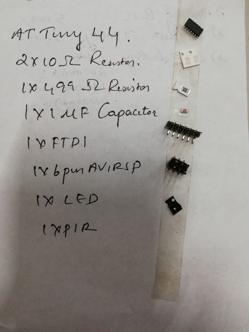
For that I primarly deisgned a board using Autodesk Eagle using the following components
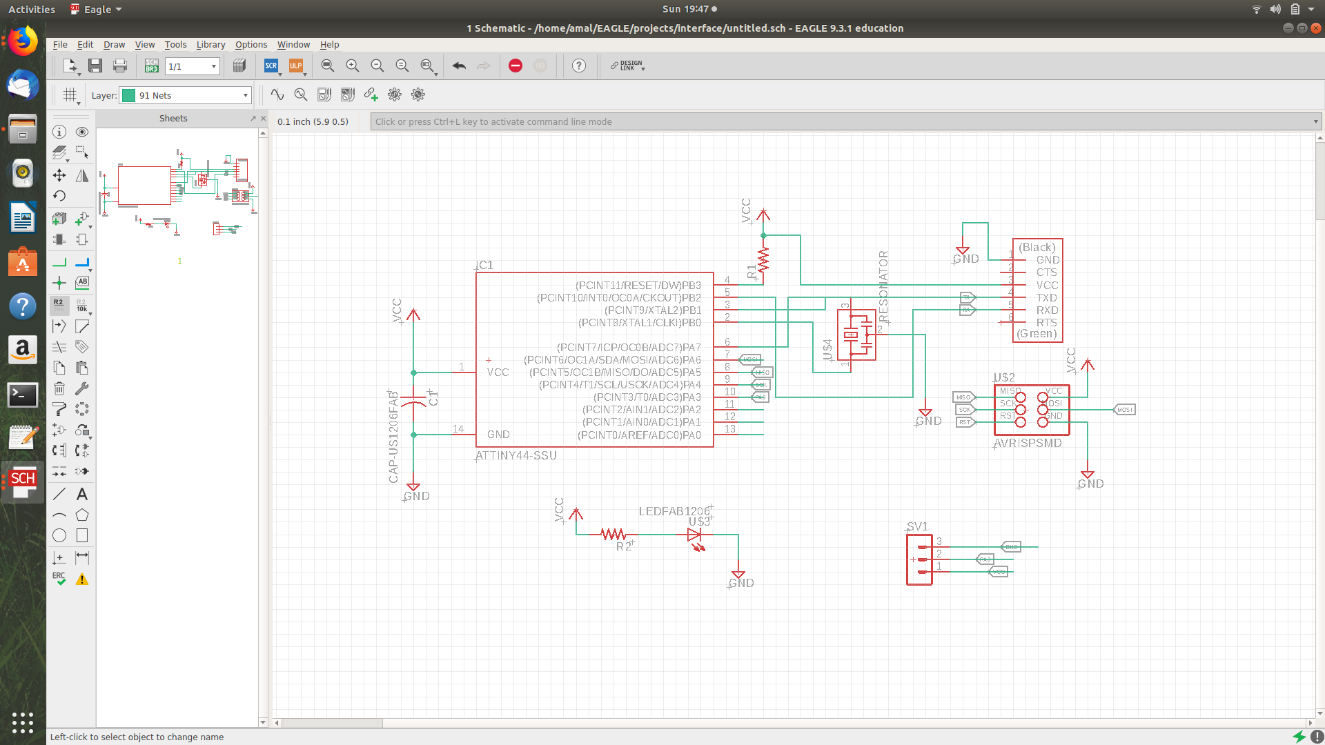
- AT TINY
-
Resistors of 10k and 499k
-
Capacitor of 1Uf
-
FTDI 6 pin header
-
AVIRSP 2*3 Pin header
-
1*3 pin headder
-
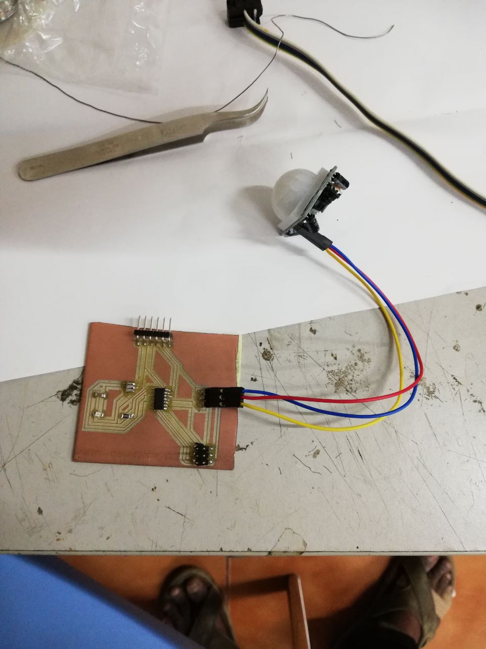
PIR Sensor
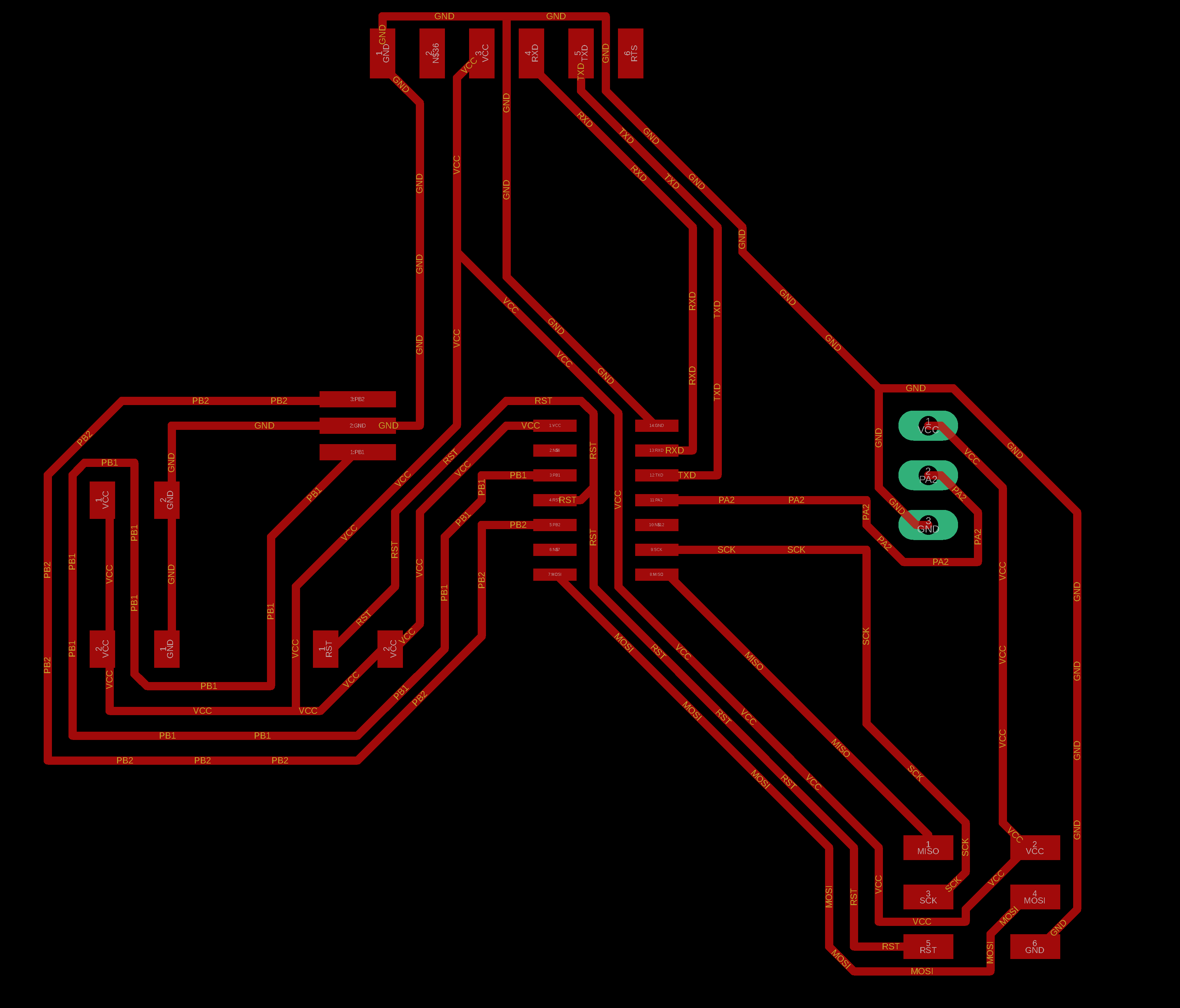

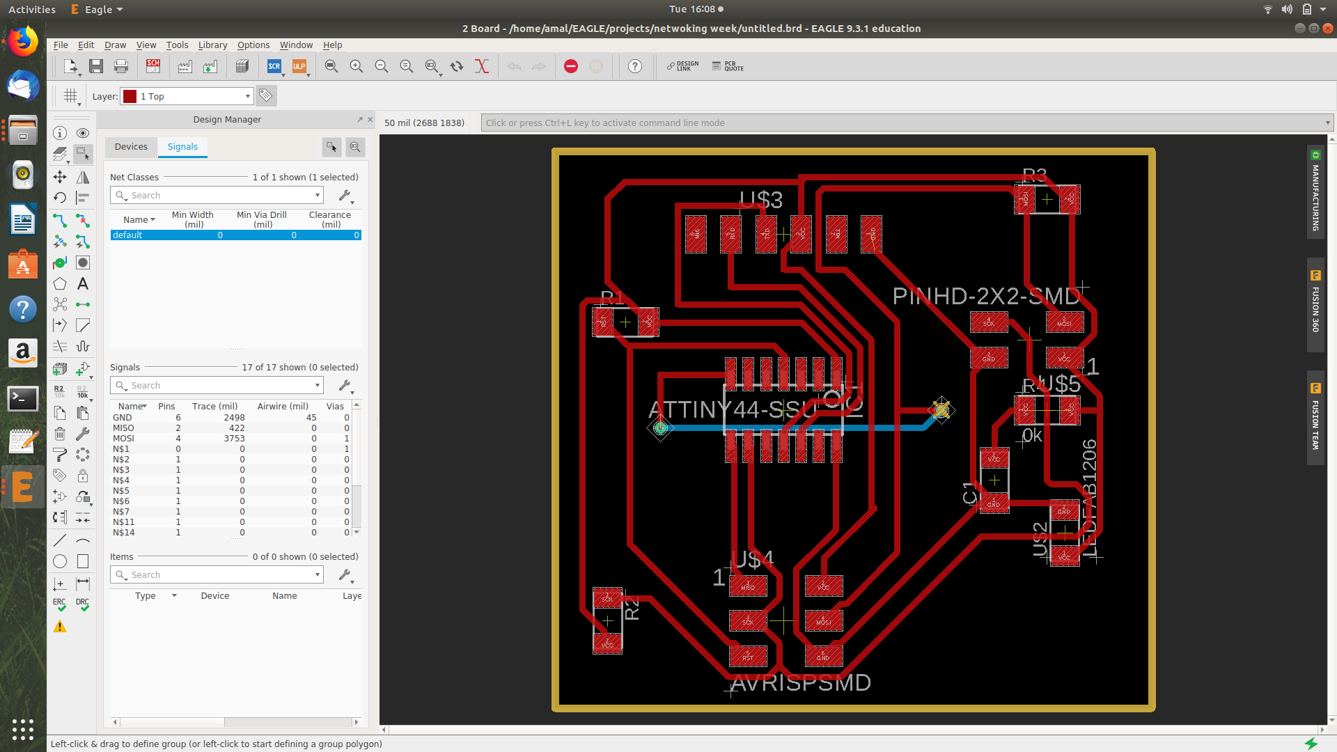
After Completing the routing I saved the file into png format and milled the board by using the MDX 20 milling machine
After that soldered the board and programmed as to show the serial input as 1 and 0
#include<TinyWireM.h>
#include<SoftwareSerial.h>

  #define PIR 2
  int data;

  SoftwareSerial serial(PA3,PA7);

  void setup()
  {
    serial.begin(9600);
    pinMode(PIR,OUTPUT);

  }


  void loop()
  {
    data = analogRead(PIR);
    serial.println("1");
    delay(1000);
  }
  )
ENTERED THE PROGRAM
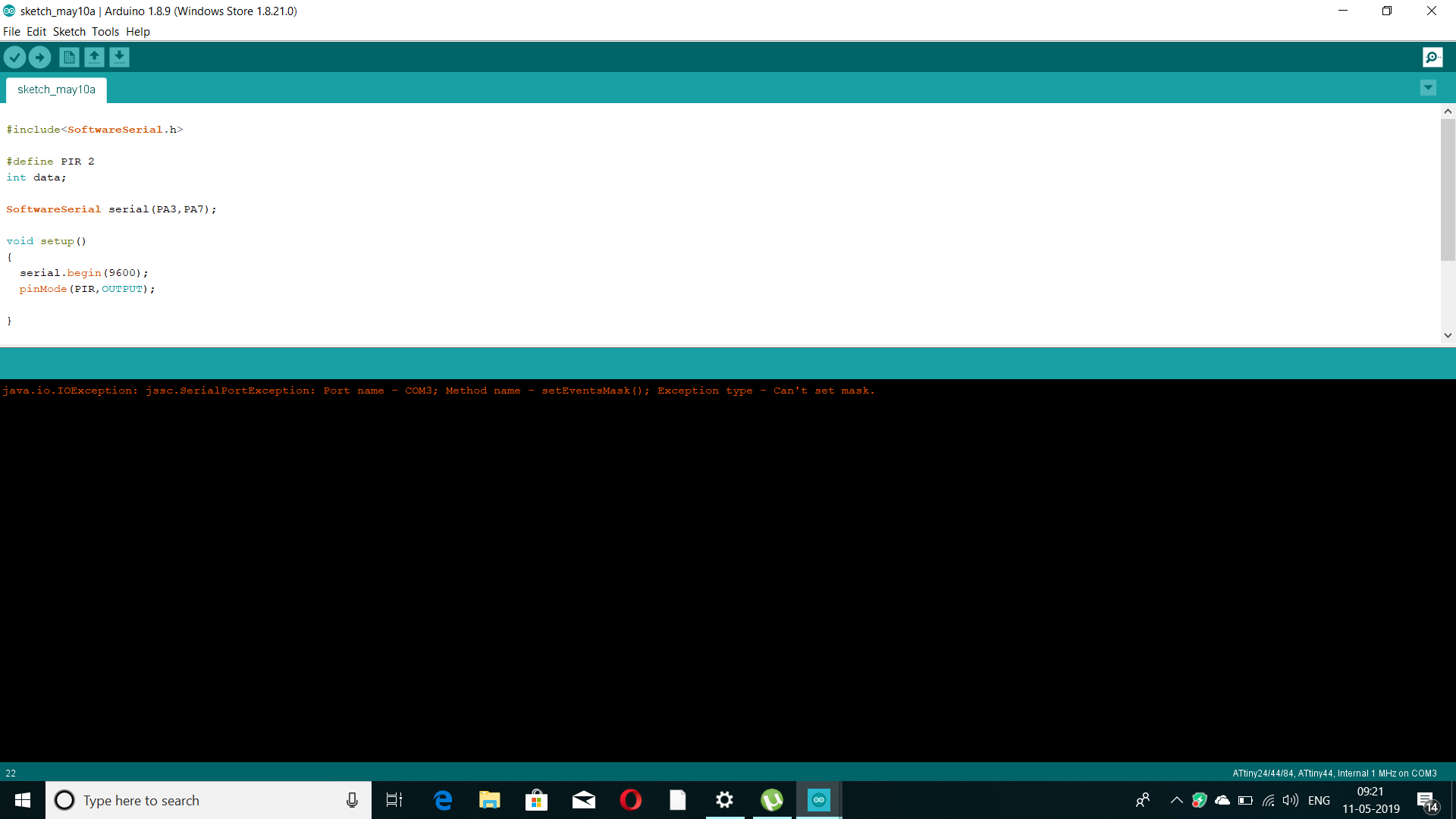
The Program was entered and the uploaded after burning the boot loader bust some java script error was shown and then I removed the AVIRSP Pin and the progrmmer and recoonected
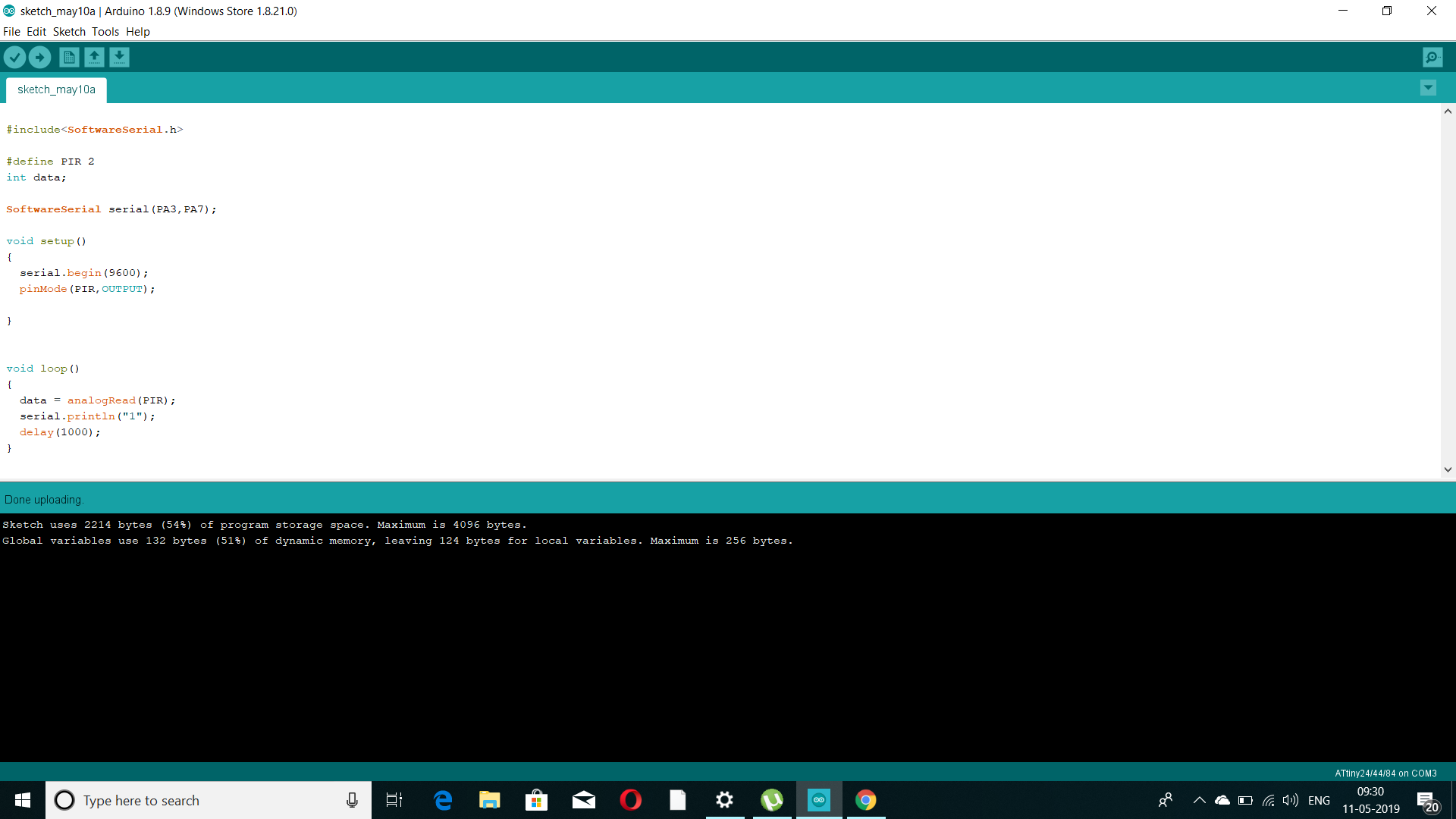
This time the program was burned .
SERIAL OUTPUT
The serial output was shown as 1 and 0.If the PIR detects any human presence,then the value shown will be “1” and if not the value will be “0”.
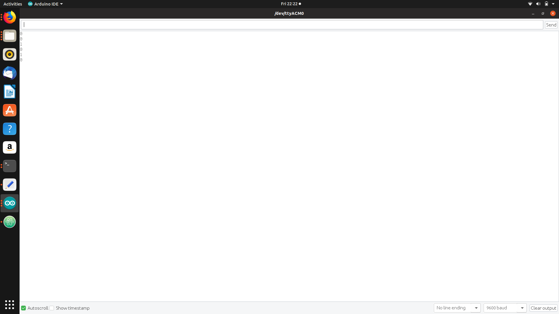
CLICK HERE TO DOWNLOAD THE VIDEO
FILES