7. Electronics design
This week was based on designing of a simple “HELLO WORLD” board of Neil Gershenfeild and adding an extra switch and LED connected over it and the group project was based on usage of test equipment in your lab to observe the operation of a microcontroller circuit board
.Tool Selected
1.The tool selected for the designing process was Autodesk Eagle and this was the very first time I was using it.
2.Before going through the designing Ie through the Neil’s board in the academy site.
3.Then I installed the Autodesk eagle and downloaded the FAB library from the academy site.
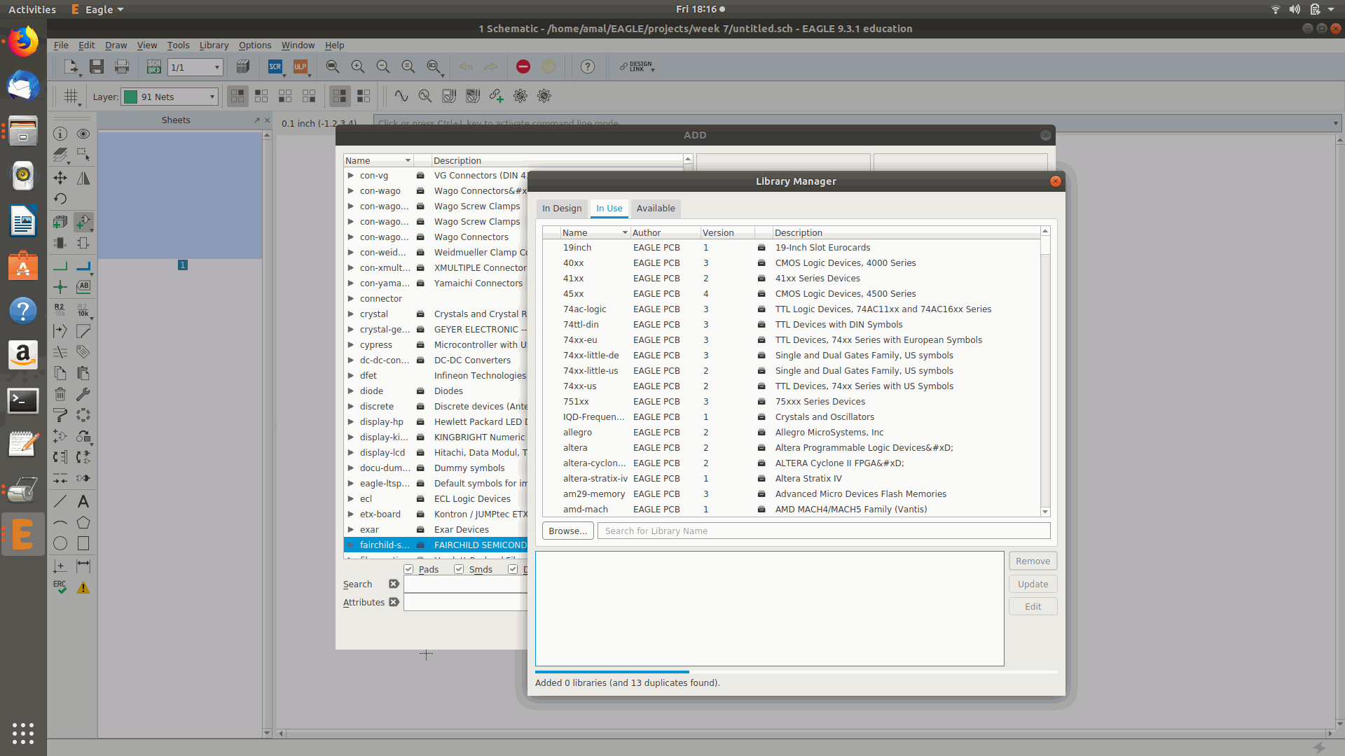
4.Then by using the library manager I updated the library.
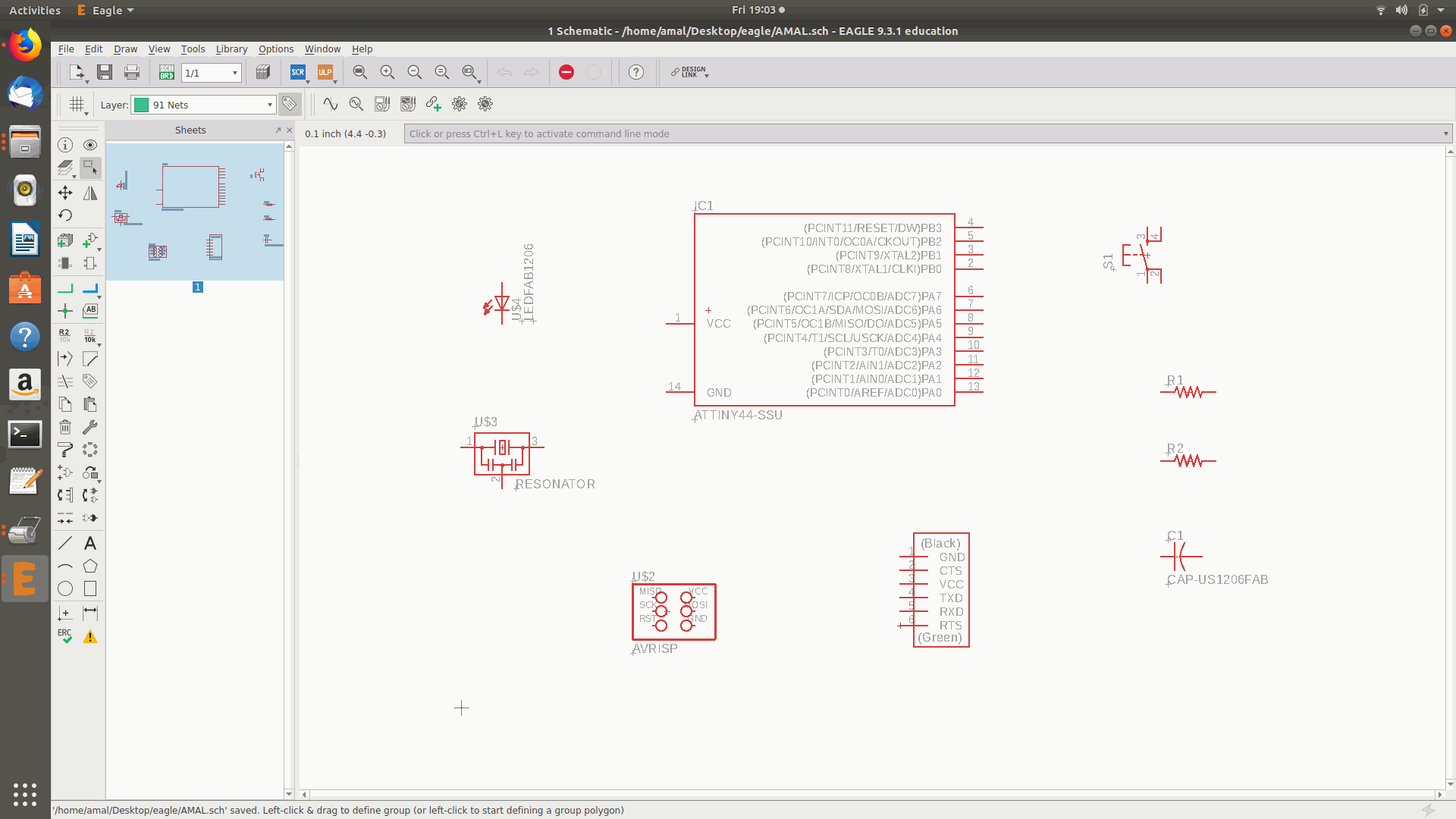
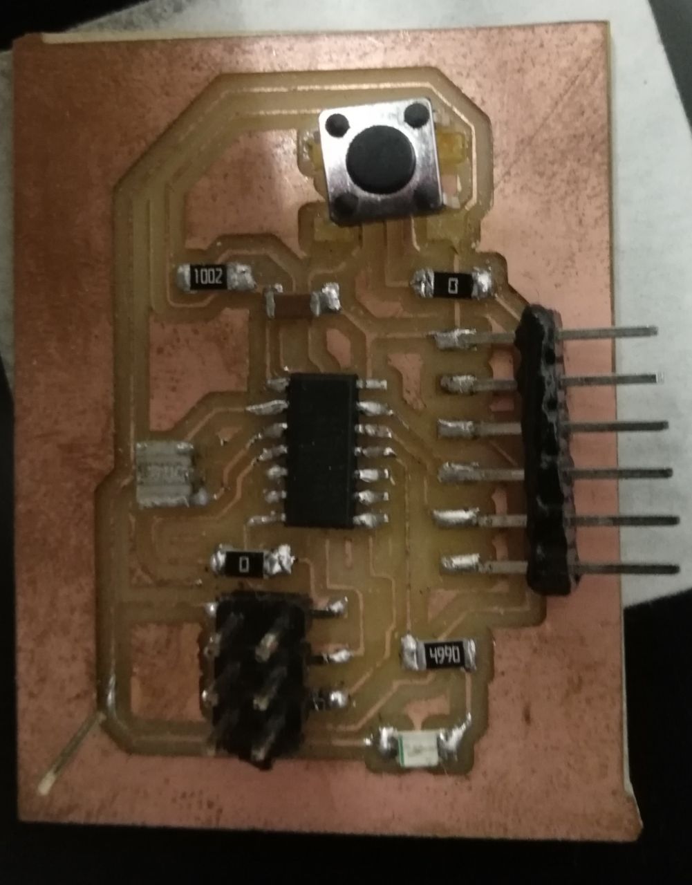
5.The I started to design the estimated boards right after identifying the estimated components sited below.
(i)ATTINY 44 X 1
(ii)10K resistor X 2
(iii)10uF Capacitor X 1
(iv)FTDI Header X 1
(v)AVRISP Header pin 1 X 6
(vi) 20Mghz Resonator X 1
(vii)RED LED X 1
(viii)Push Button X 1
(ix)499 Resistor X 1
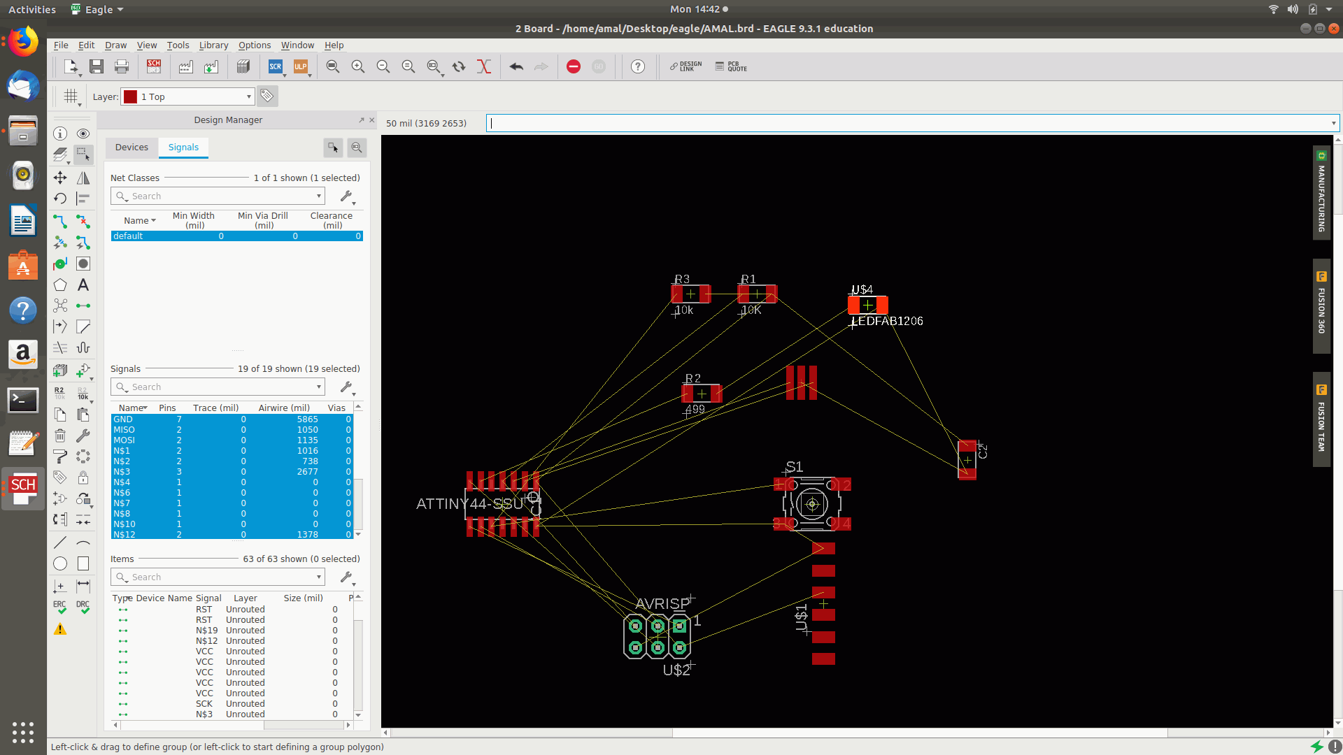
6.After that I arranged the components and named the connections like VCC,MOSI,MISO,GND etc and entered the values of the resistor and capaitor and the autojoin was formed.
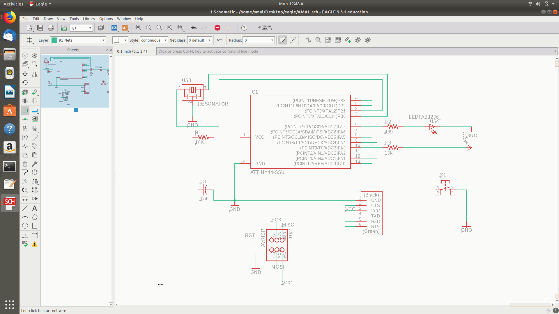
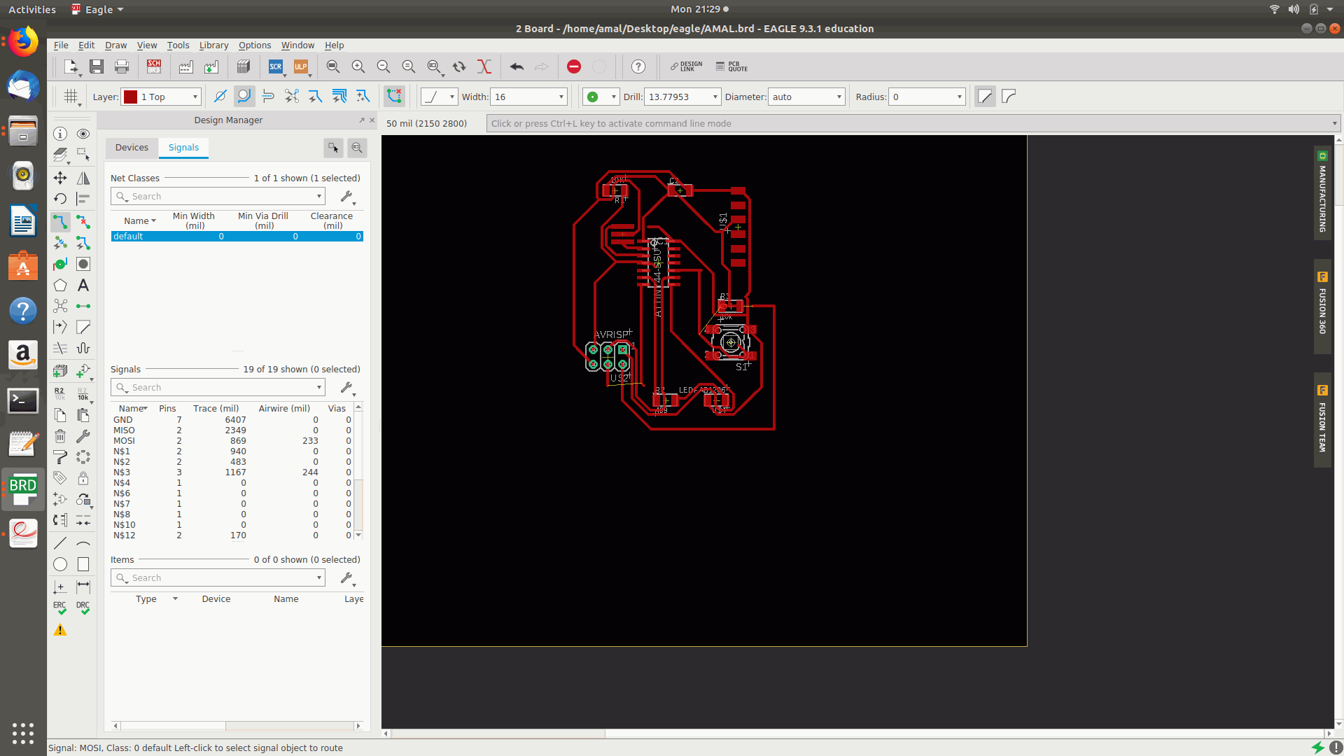
7.After connecting all the components the “Switch to Board” option was selected from the file menu.

8.Then I arranged all the components and selected the quick route option which was on the left side bar of the screen in eagle.
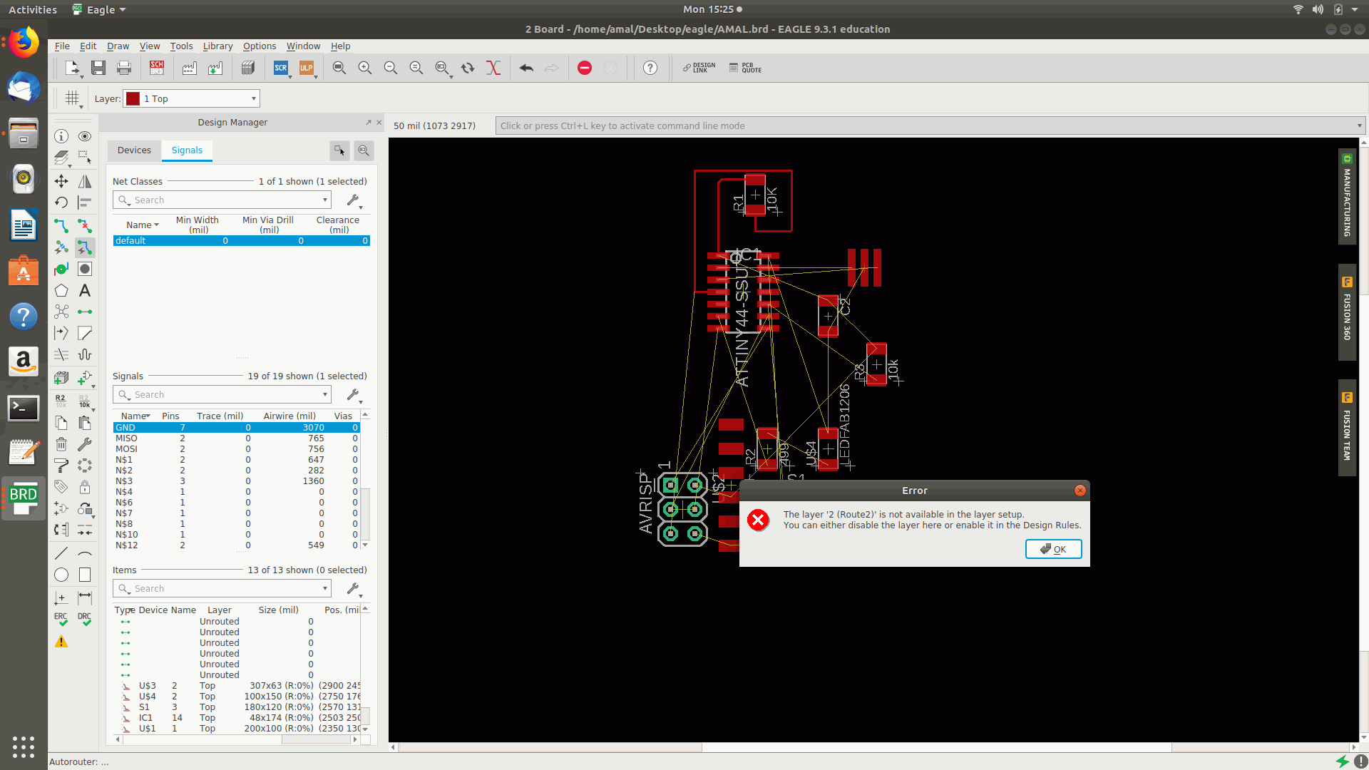
9.Then I rearranged the components since some of the components went unrouted and then I applied the autoroute option was selected from the tool option but an error occurred showing to disable the layer or to assign the design rule .
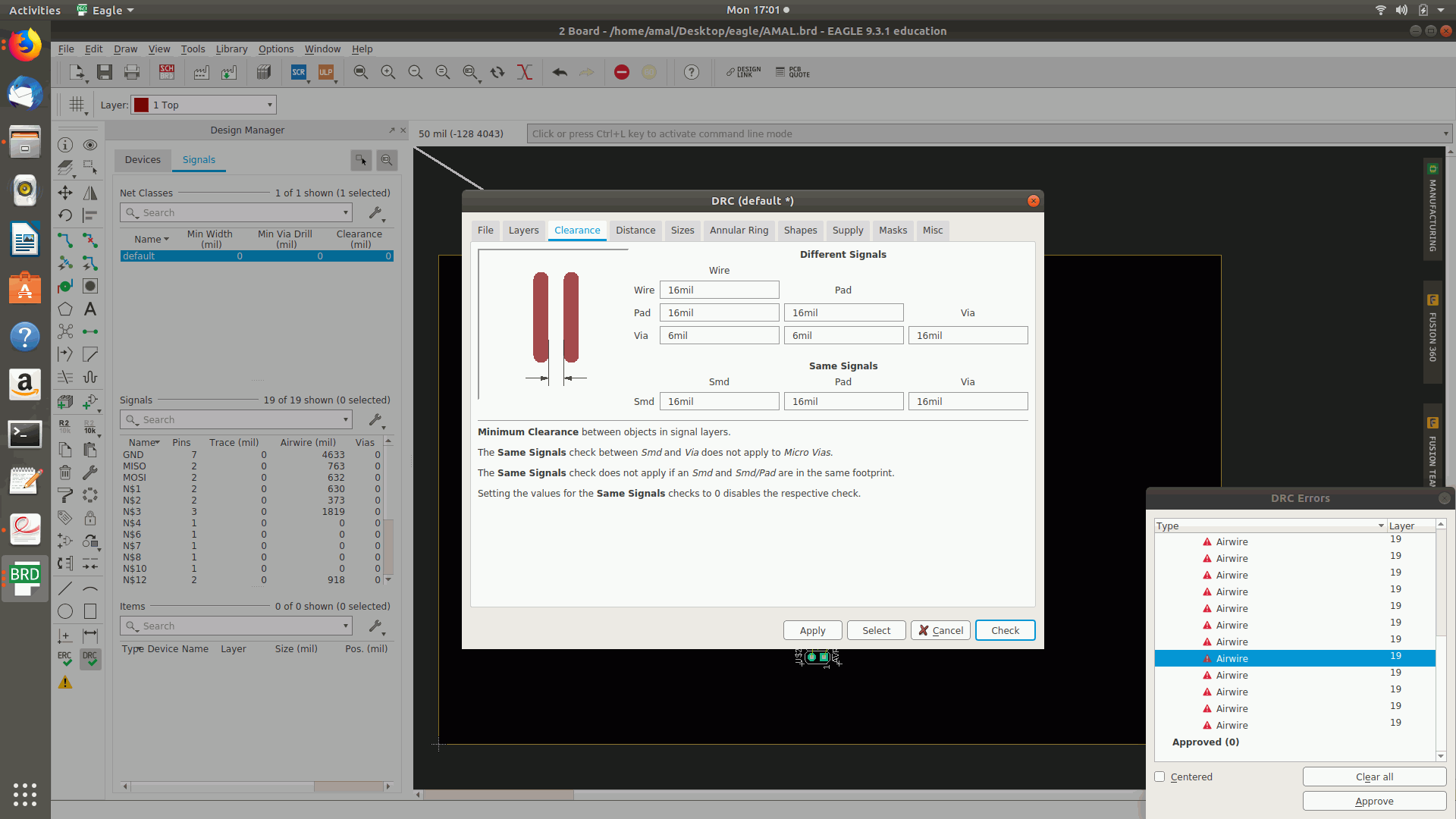
10.Then selected the design rule (DRC) as size as 16 mil and clearance as 16 mil.
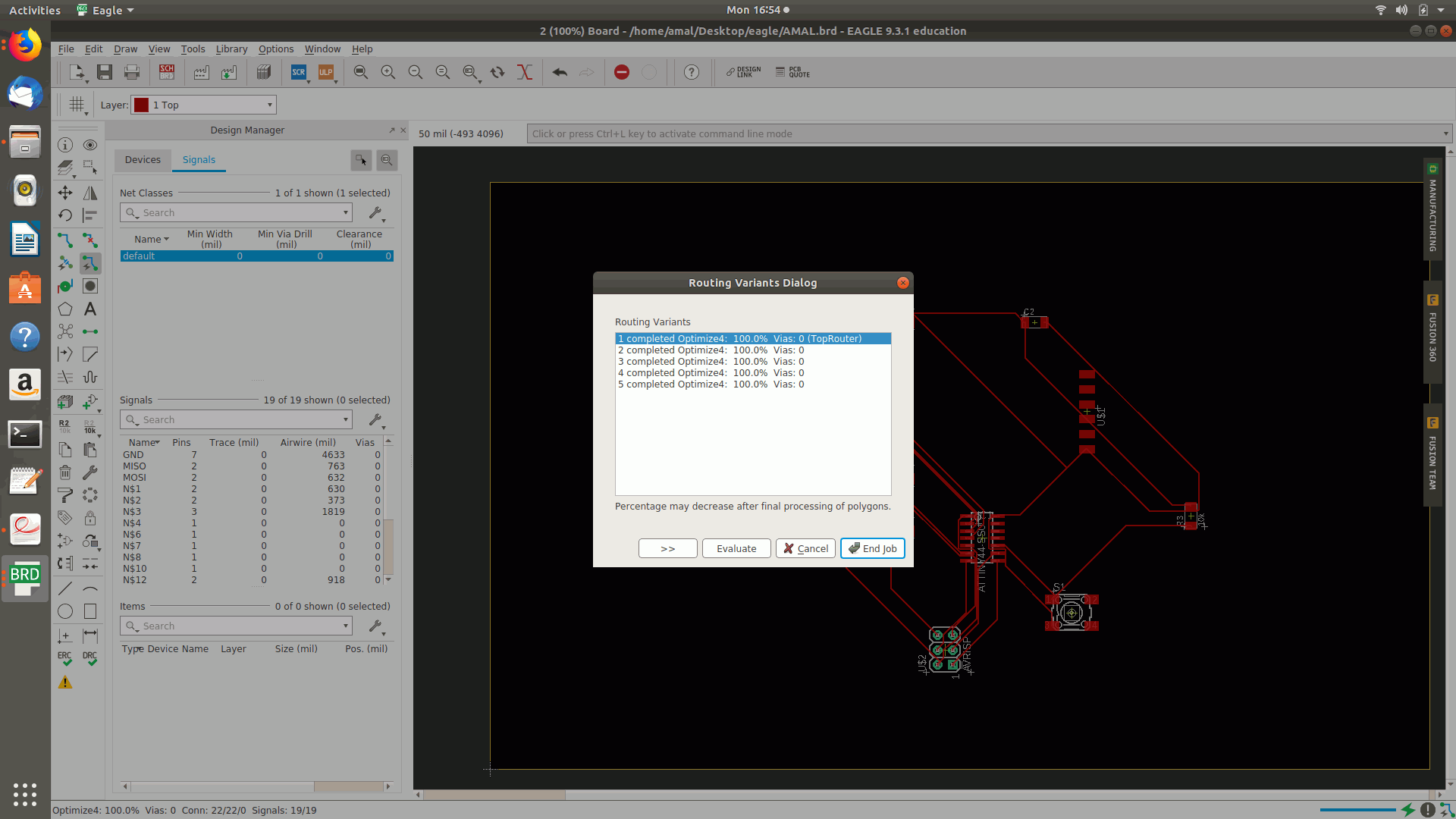
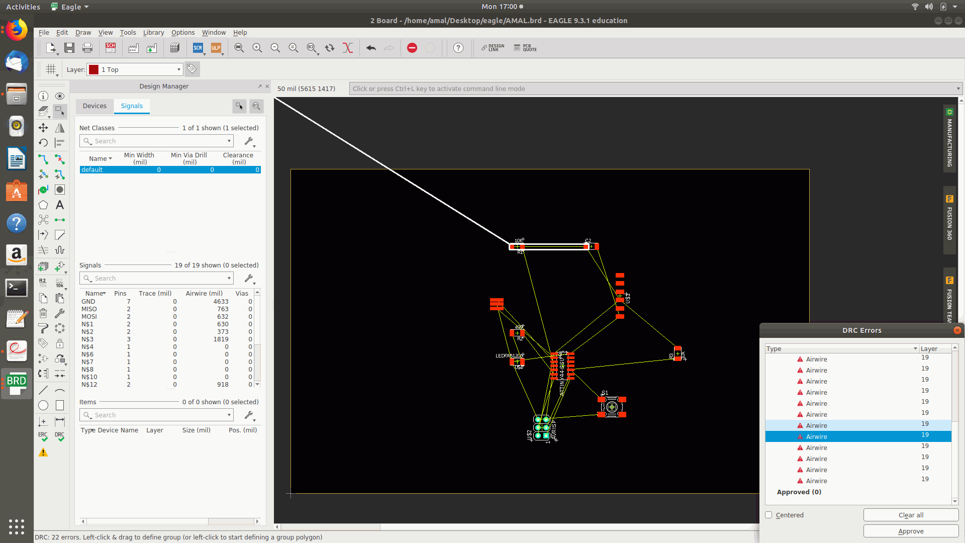
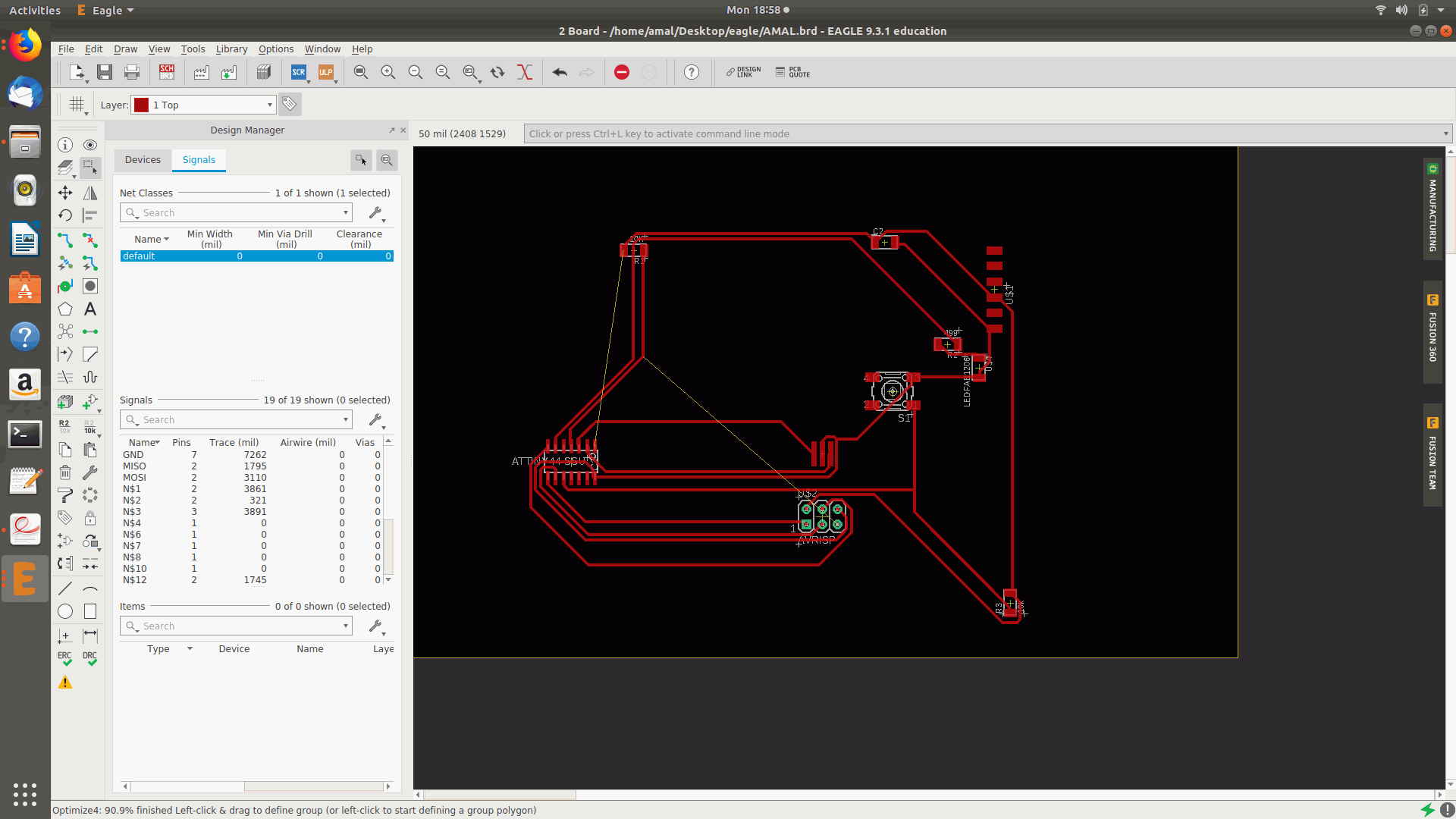
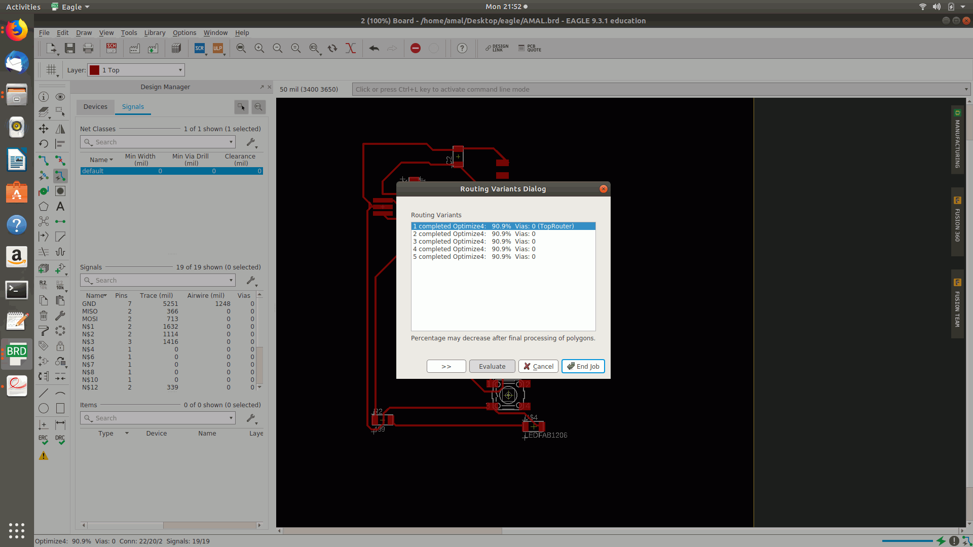
11.Then enabled the autoroute option by enabling the TOP direction option as auto and rest all as NA followed by the continue option and the top autoroute was selected which shown only 80% of the connections were routed.
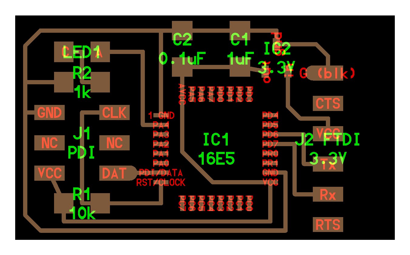
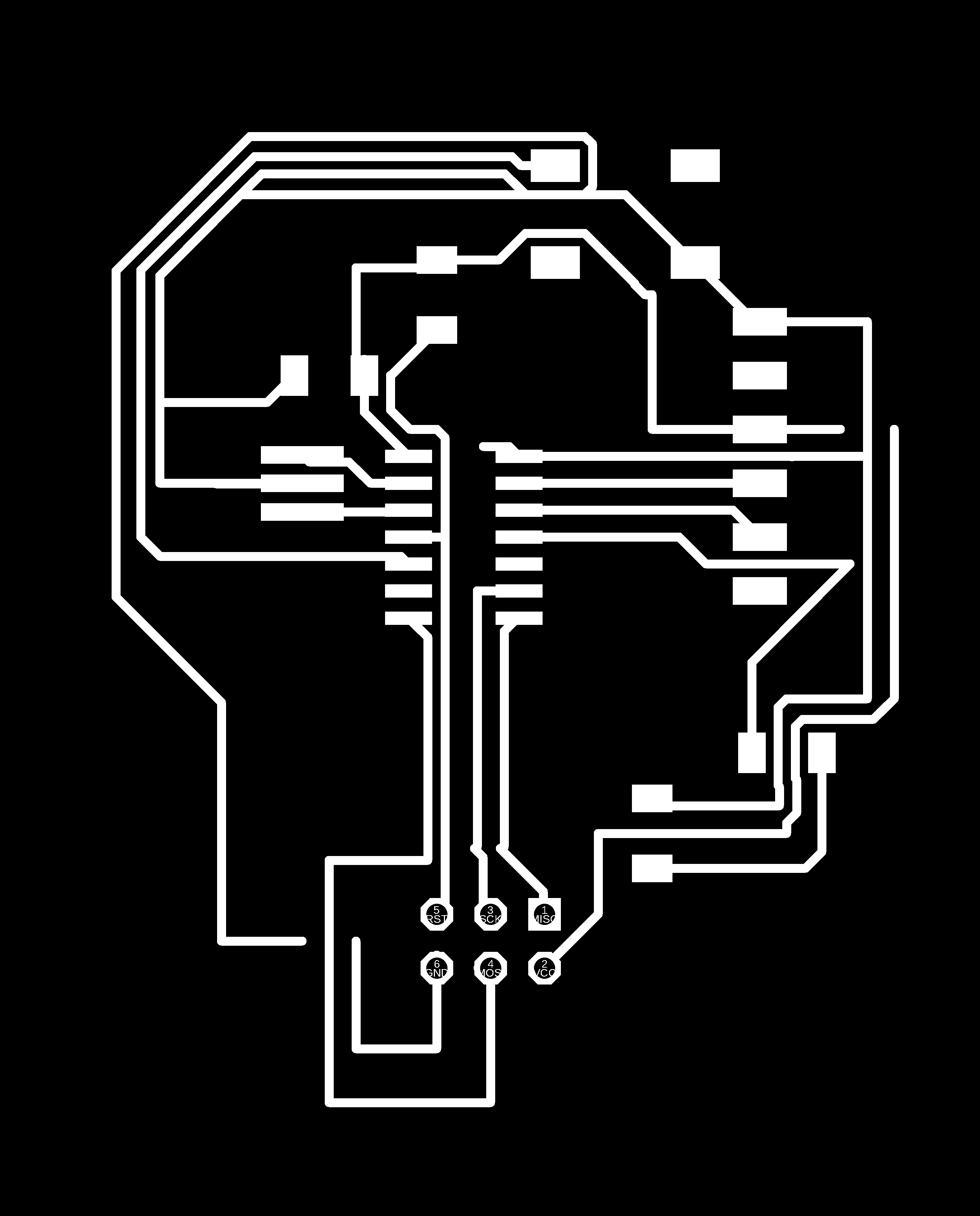
12.Then again tried as many times with different placements of the components in different directions and autoroutes and the top routed percentage was on 90.8% and the after selected the layer and turned off the visible layers other that top,bottom,pads etc and saved the image as png and the followed by making the border for the board.
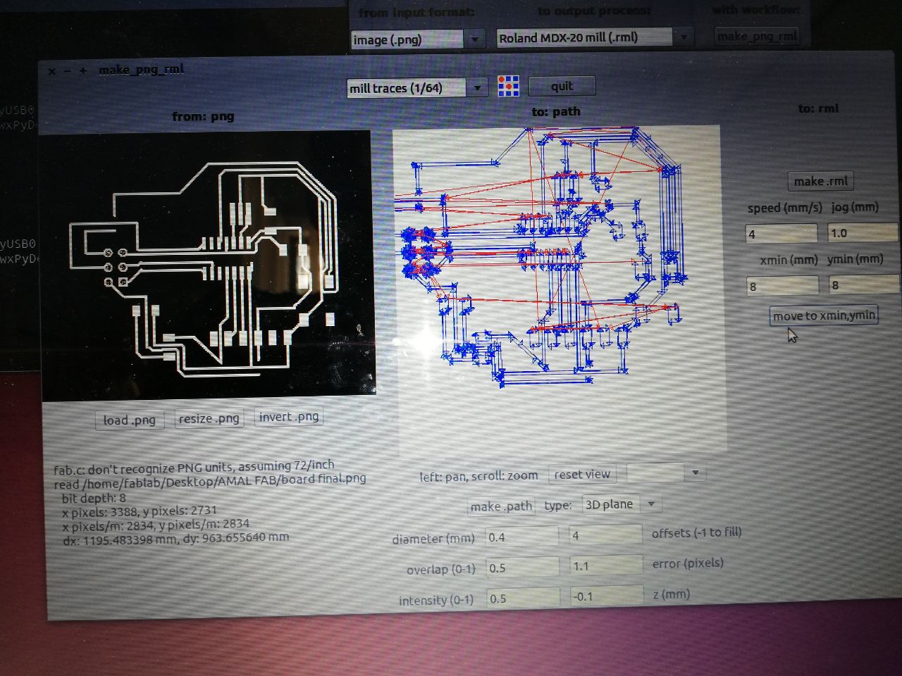
13.But it seems that the selected components went wrong somewhere and I begin to identify the mistake and went back to the Schematic diagram and identified that the connections to FTDI was not properly connected and I did the whole procedure once again. and the estimated redrawn diagram and the png file was set to mill using ROLAND MDX 20.
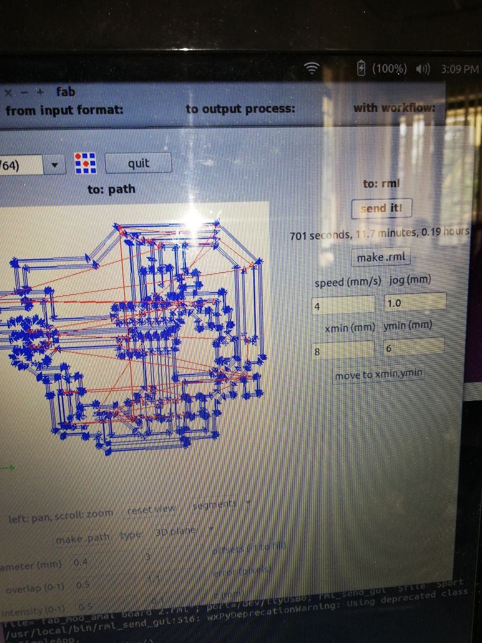
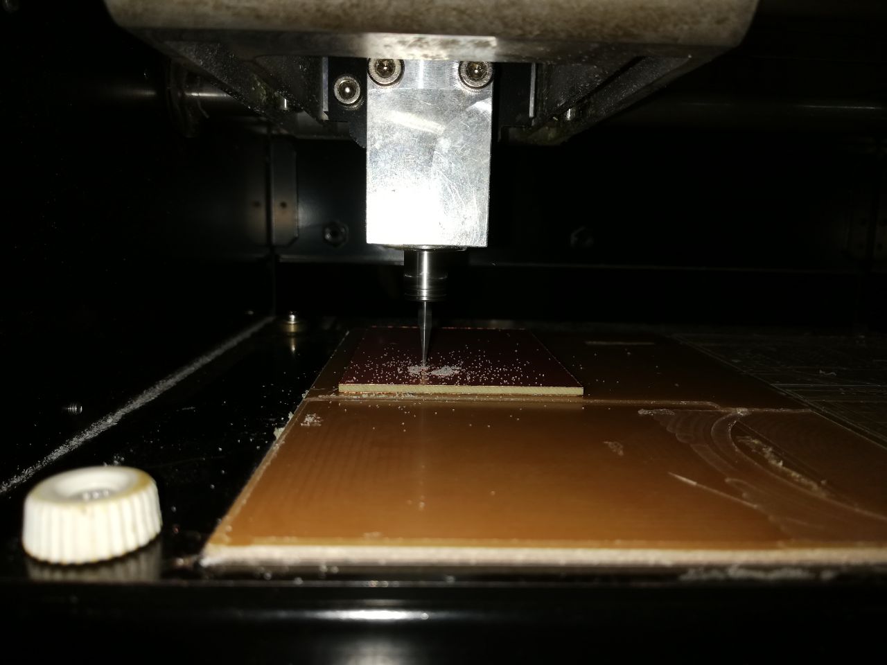
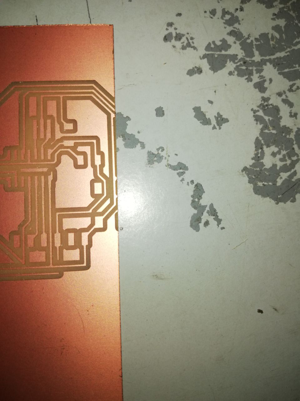
But some error occurred in between setting up the origin and I accidentally selected 0.2mm extra and couple of traces went outside the board and the board left milled incomplete
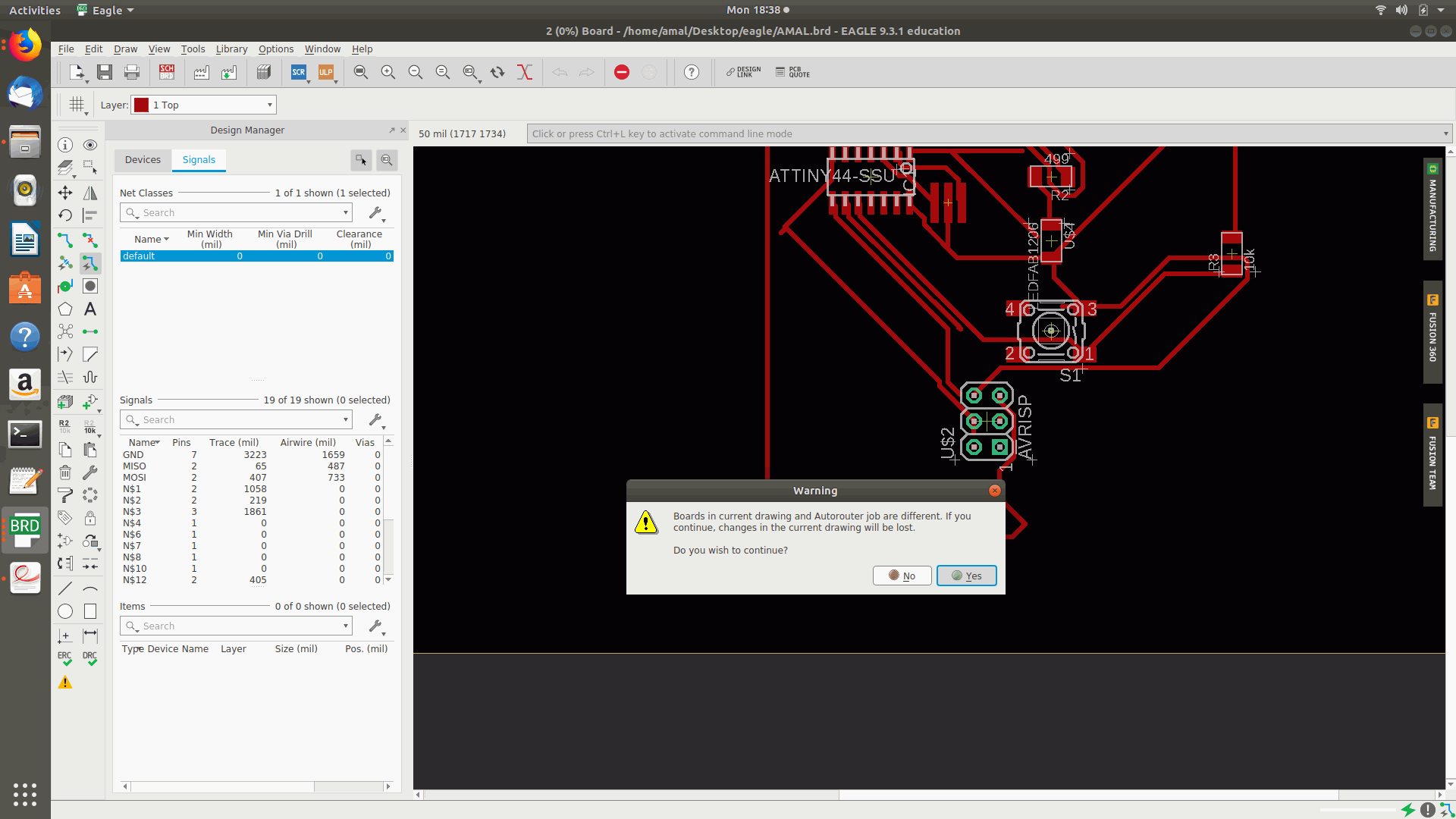
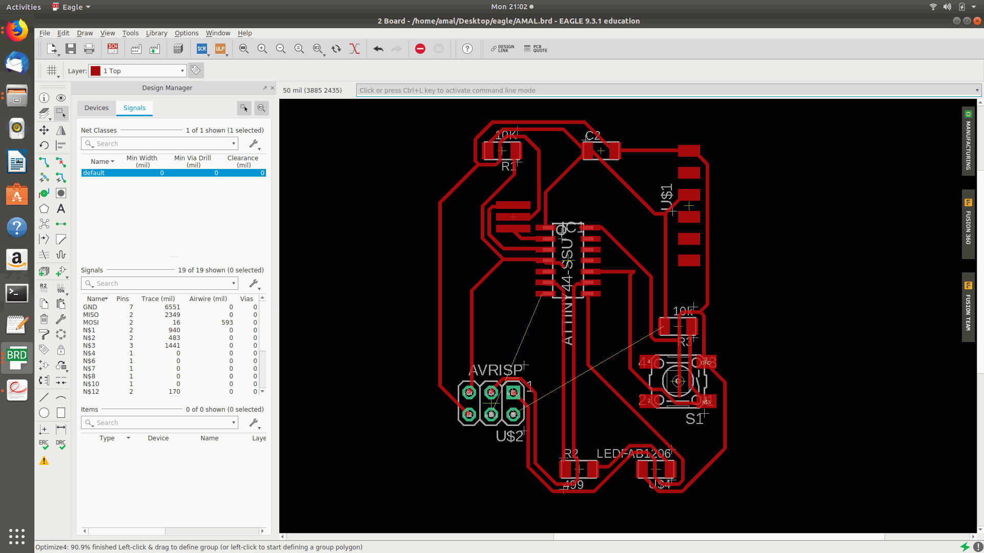
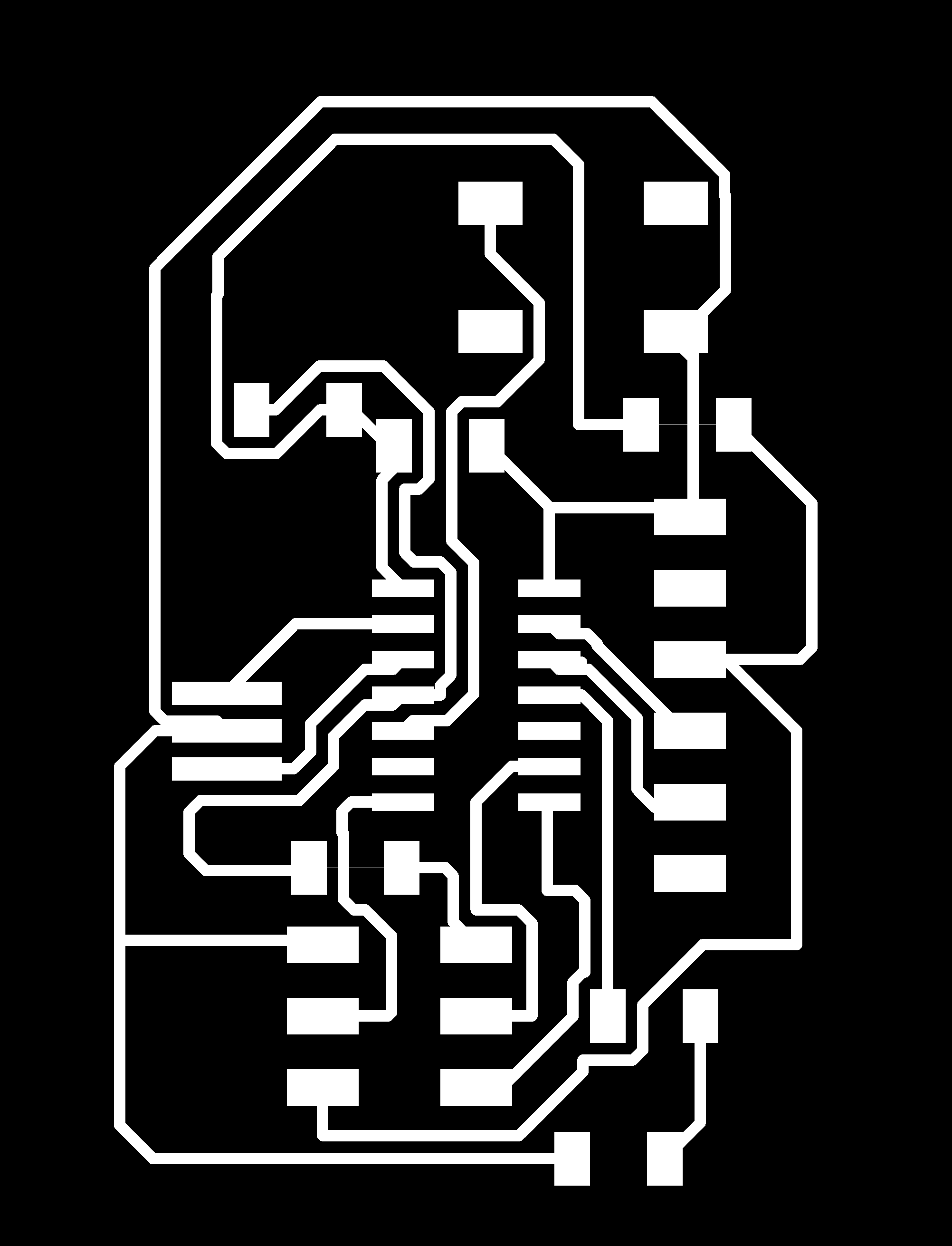
Even though the design was formed i was not satisfied with the design and planned to ripup all the connections and planned to reroute and finally I got the the rerouted design as follows below.

And then planned to do the milling again and fabricate the board.
After completing the soldering works planned to connect thE ftdi header to usb and then to pc.
BY this I had Completed my Electronics Designing week .
GROUP ASSIGNMENT
The group assignment was of testing the electronics equipment in the lab to observe the operation of a microcontroller circuit board.
We started to test our equipment in our lab.

MULTIMETER:A multimeter or a multitester, also known as a VOM (volt-ohm-milliammeter), is an electronic measuring instrument that combines several measurement functions in one unit. A typical multimeter can measure voltage, current, and resistance. Analog multimeters uses a microammeter with a moving pointer to display readings. (taken from Wikipedia)
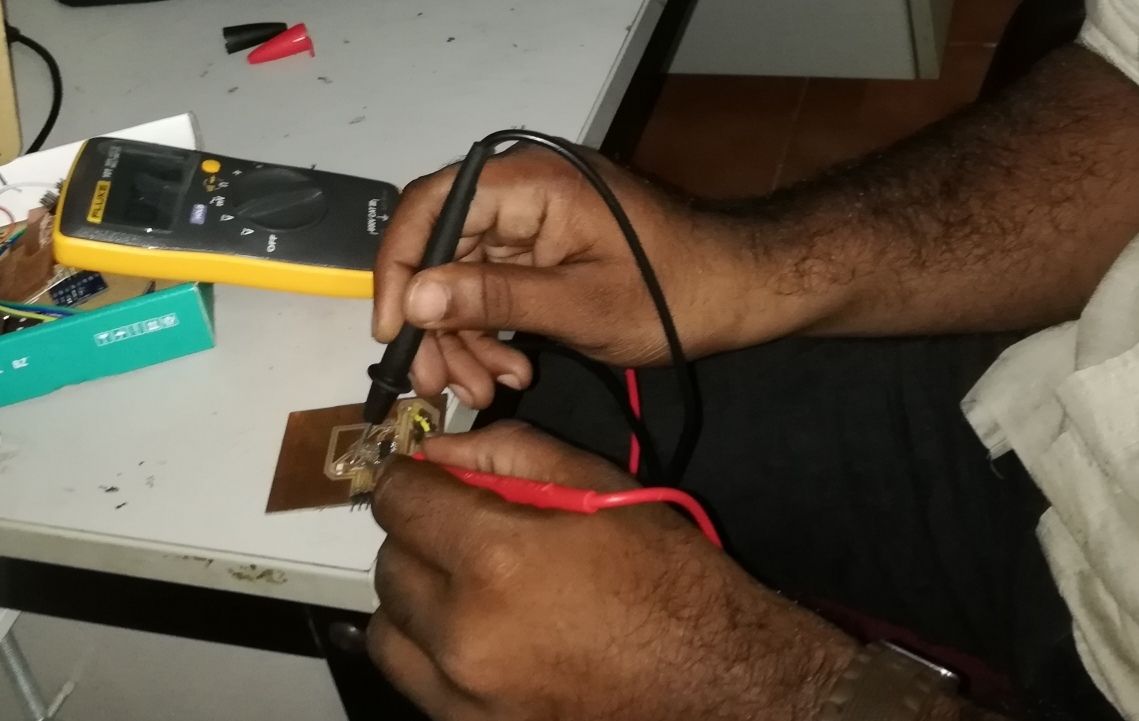 We checked the continuity of the circuit using the mutimeter.
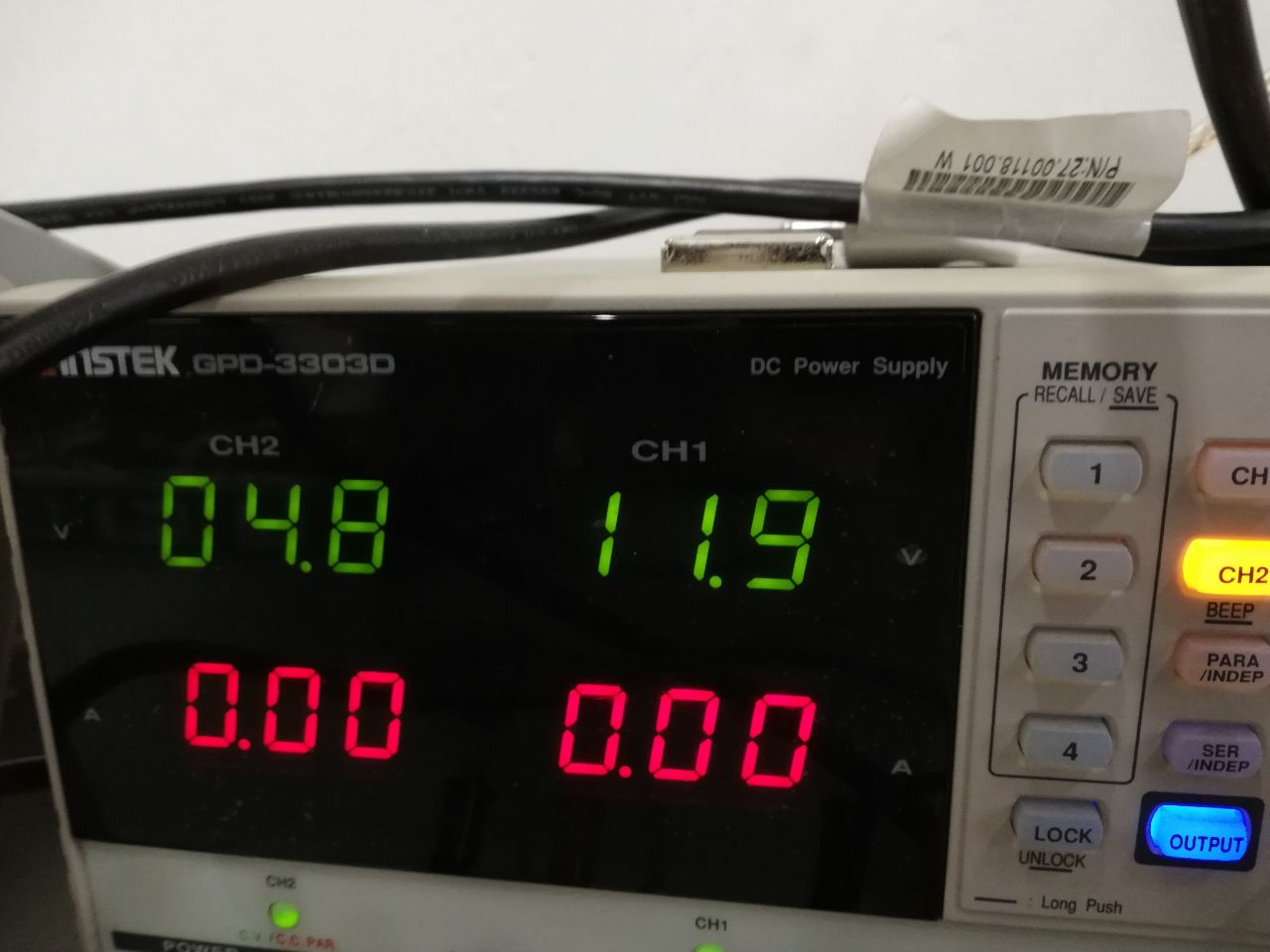
LAB BENCH POWER SUPPLY:A simple general purpose desktop power supply used in electronic labs, with power output connector seen at lower-left and power input connector (not shown) located at the rear. A power supply is an electrical device that supplies electric power to an electrical load.A bench power supply is a stand-alone desktop unit used in applications.(Wikipedia)
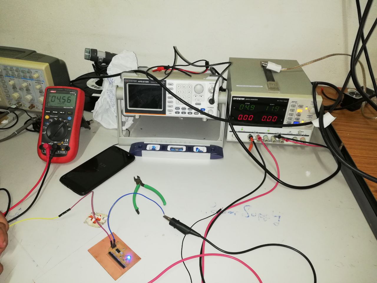
After that we had connected the board to the power supply in such a way that the VCC of the power supply to the multimeter and then to the board and the GND of the power supply to GND in the board and the 15 micro voltage was measured in the multimeter ie the consumption by microcontroller was shown.

CATHODE RAY OSCILLOSCOPE: The cathode ray oscilloscope (CRO) is a type of electrical instrument which is used for showing the measurement and analysis of waveforms and others electronic and electrical phenomenon. It is a very fast X-Y plotter shows the input signal versus another signal or versus time. The CROs are used to analyse the waveforms, transient, phenomena, and other time-varying quantities from a very low-frequency range to the radio frequencies.(Circuit globe)