5. Electronics production
1.Group Project
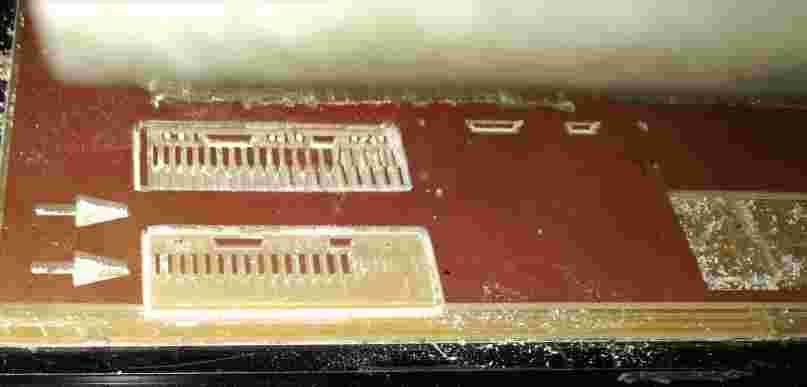
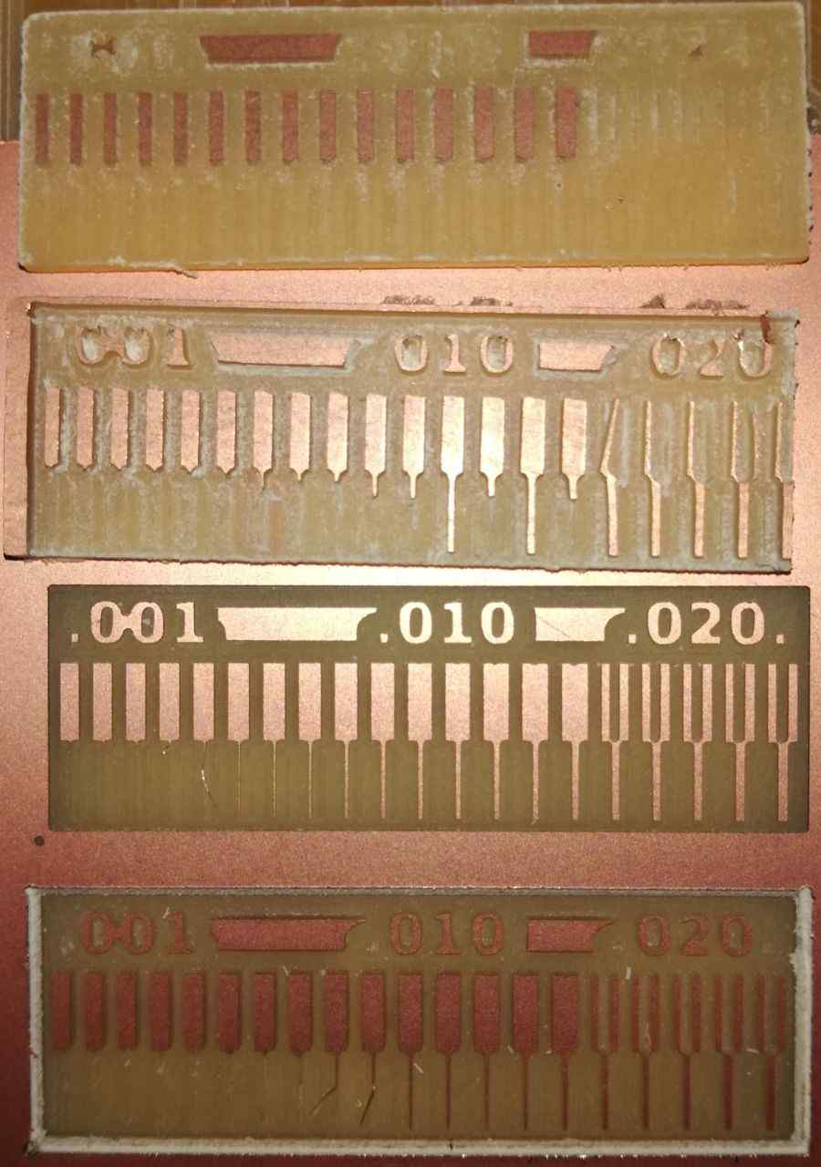
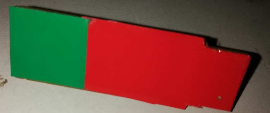
(1)The group project was regarding to cut and mill the trace using milling machine at various depths.


(2)The main objective was to know the minimum mill width at various measurements .
(3)While cutting the board the copper traces were ruptured and we repeated the process.
(4)While doing the work we accidently resized the image and instructor referred to use the original image in the academy site for milling purpose.
(5)After that we milled it again by using the original image and then also the copper strands were ruptured.
(6)Then identified that the bit was broke and then we did the whole work again.
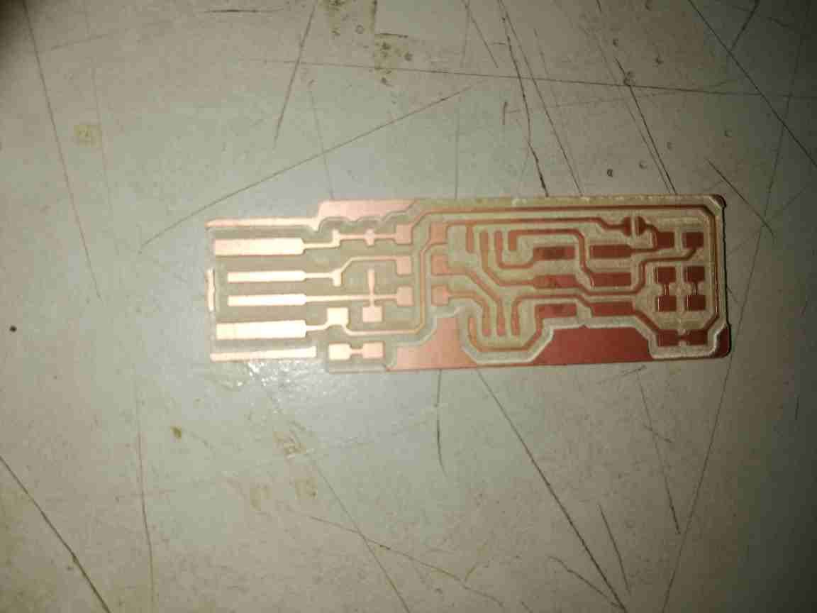
(7)After replacing the bit I tried once more with 0.4 offset and this time the strand were more visible and understood that it can cut upto the thickness of 0.3 width and the rest all strands in that were torn.
This week was dealing with the production electronic board with reference to “Bryans Kit as indicated in the fab academy site.
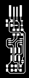
The very first thing I did was to go through the Brian’s page and study the basic details regarding the electronics production week and it is understood to create a usb ATTINY microcontroller based programmer.For that the very first thing to do is to download the traces and cut out figure of the estimated programmer which is to be constructed.

After that the process included
2.Characterization of the board,components and the procedures to take the materials from the component library.
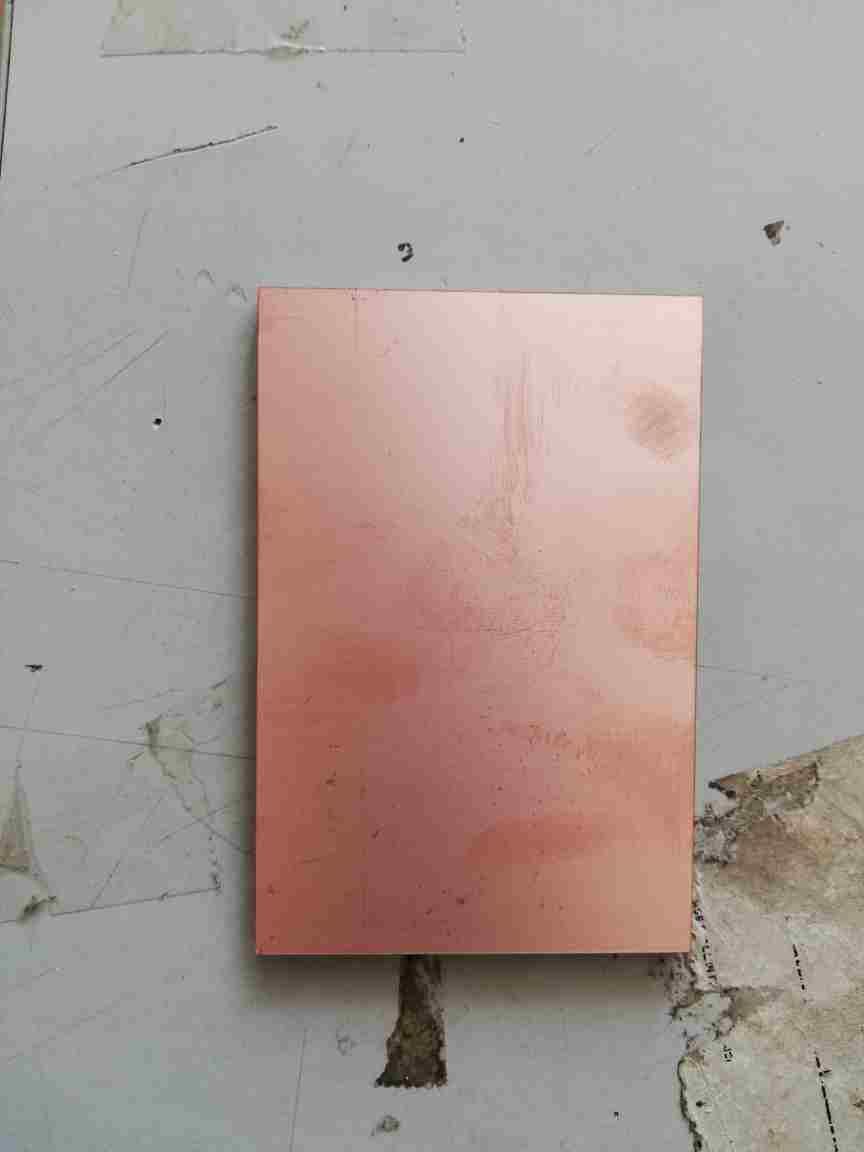
(1)Basically the copper board is used for circuit development.
(2)Hopefully it was the first time to see SMD components
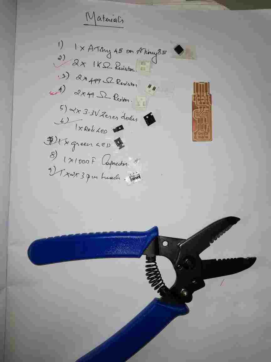
(3)The instructor guided the how to take the materials from the component library by sticking a double sided tape on the list of components needed and the materials were estimated by the reference.
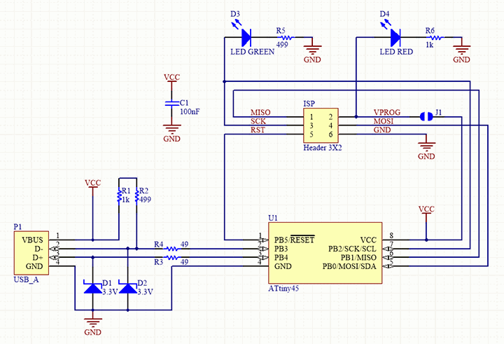
3.Analysing of Brian’s Board.
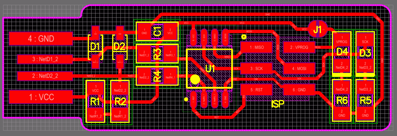
Bryns board were analysed and the following materials were estimated.
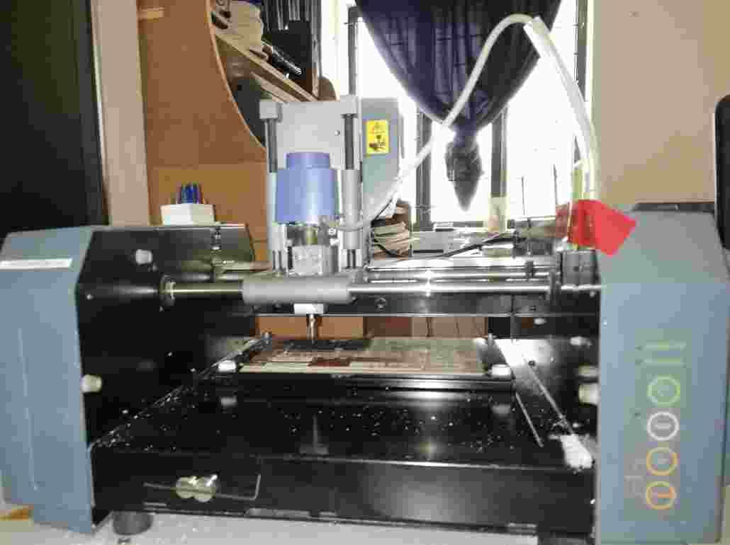
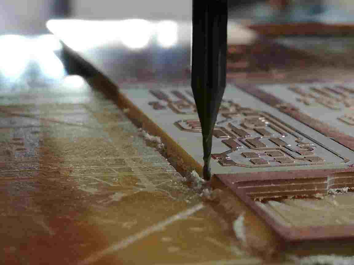
4.Milling the circuit.
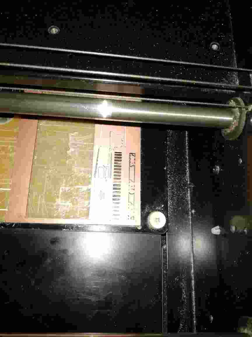
(1)The board were milled by using a ROLAND 200 MD machine.
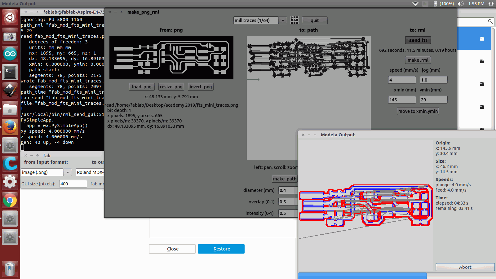
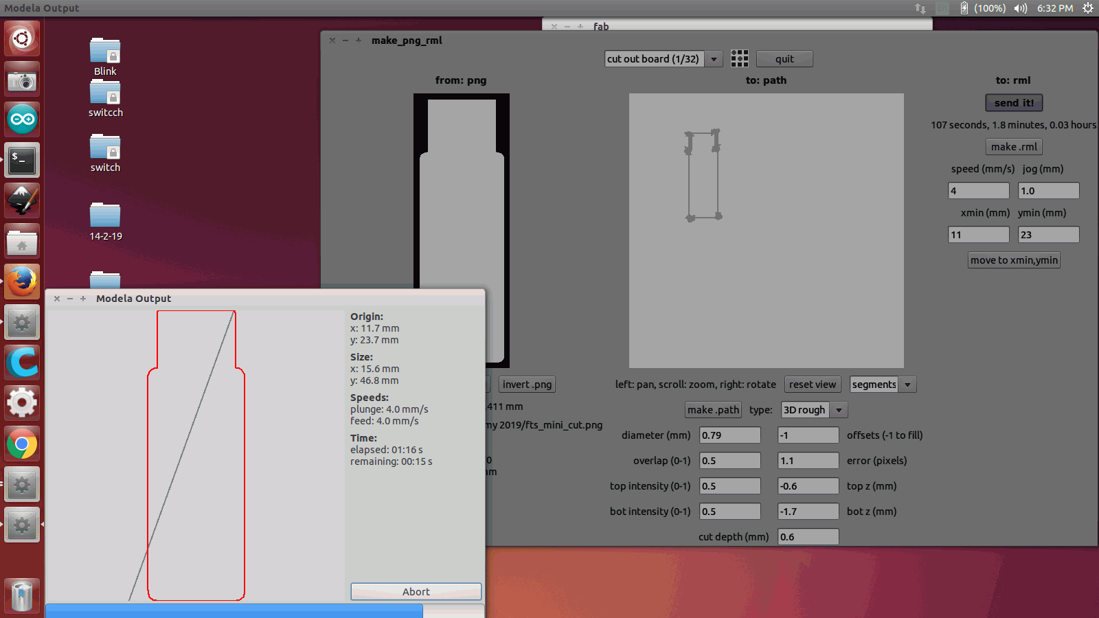
(2)Primarily by using the terminal the machine driver dialogue box were set using the command fab.
(3)Then selected the machine and the material from it and opened the driver software.
(4)Then selected the materials,set the feed ,and loaded the png file .
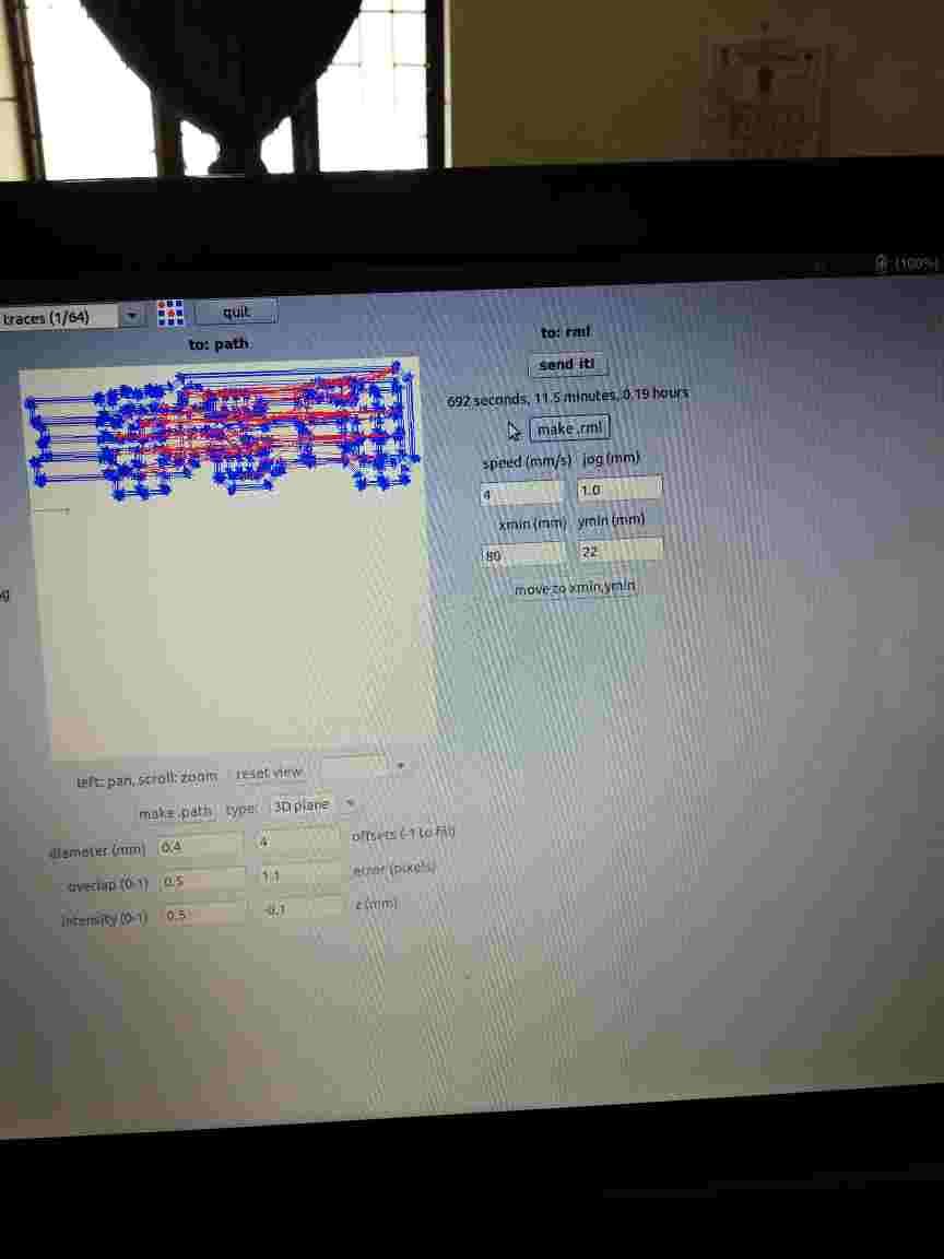
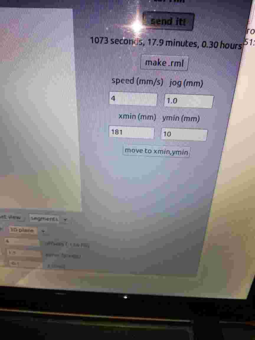
(5)After that the material cut path was defined by using the make path option and the made the rml file.
(6)Then the board was stuck to the milling machine by using a double sided tape and ensured that there is not any air holes and bending otherwise the traces will not be cut and the bit used for the purpose of 1/64 inch bit for making traces and 1/32 for cutting.
(7)Then by using the send it option the milling operation was started.
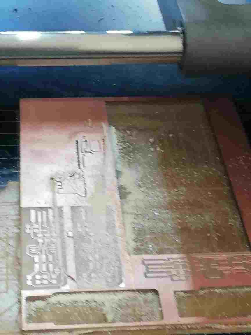
(8) While dealing with the cutting operation there was a problem in setting of y and z axis.THe y axis setting went wrong and the whole board got ruptured and while setting the z axis the depth was high because of using v-bit.
5.Surface material Soldering the components.
(1)This is the first time i was dealing with surface mounted devices.
(2)As per the guidance the instructor advised me preheat the board using soldering and to paste components were pasted with solde in small amount and he also instructed make the soldered joints shiny.
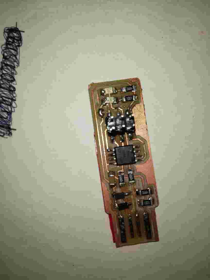
(3) After finding the SMD the components were placed according to the circuit estimated and made sure that all the joints were soldered properly and firmly.
(4)During the soldering process the following problems occurred.
(i) Resistor were not properly soldered and it came out.
(ii) The 2/3 header pin was wrongly placed and by using a breed it was pulled out.
(iii) The header pin soldered was slightly tilted ,so I managed to de solder it again using hot air gun and while using this the pin was slightly burnt.
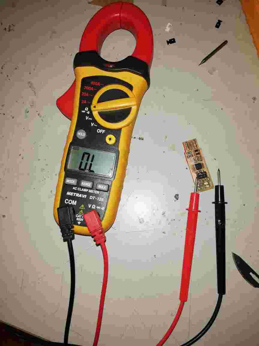
(iv) Alas the connections were finalized and it was checked by using a multimeter in continuous mode.
(6)Finally all the components were soldered and checked.
6.Programming the ATTINY 45.
(1)Before programming of ATTINY 45 I went through Brian’s page again.
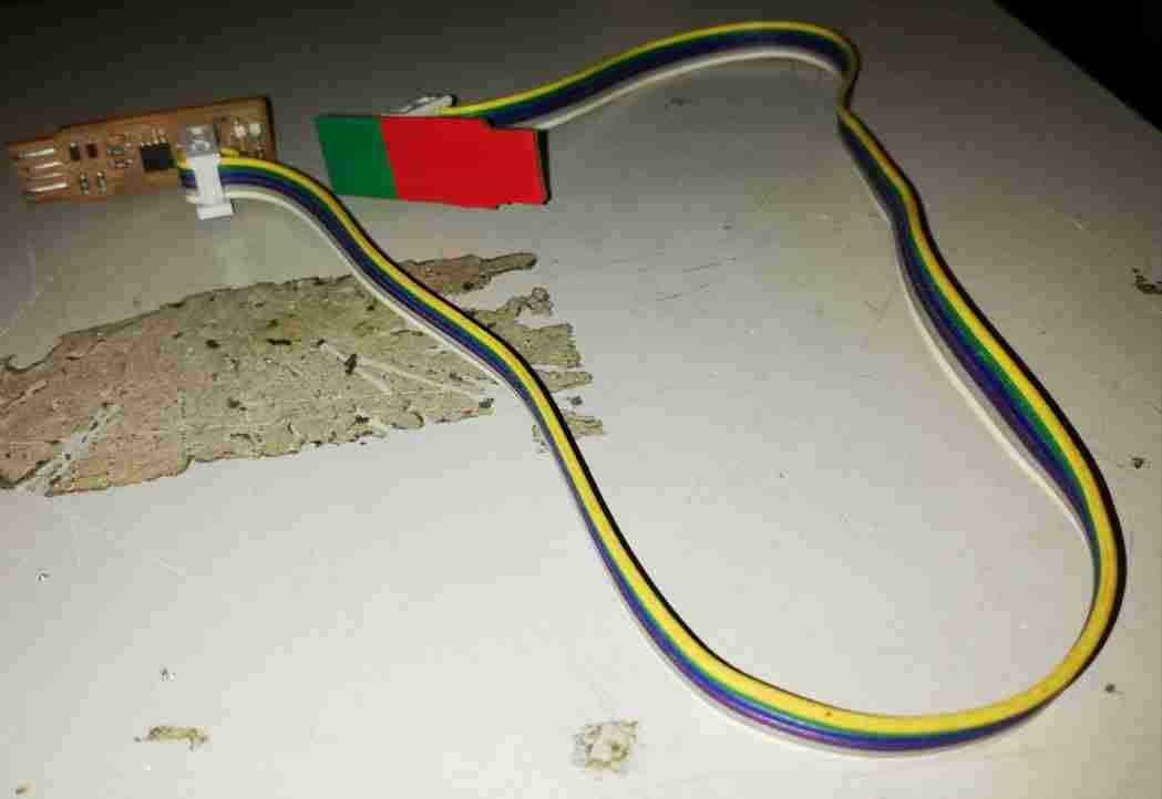
(2)After that the ATTINY was interfaced with another ATTINY using a flat cable connected to 2/3 header pin.
1) Downloaded the firmware by command
sudo apt install avrdude gcc-avr avr-libc make in the terminal.
2)Connect the programmer which is another usbtiny to our usbtiny and plug the programmer to the computer. This time the red LEDs in both the programmer shall be on.
3)Extracted the folder fts_firmware_bdm_v1.zip.Opened a terminal in the above folder and gave command
avrdude -c usbtiny -p t45 to initialise the AVR device.
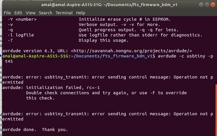
(4)Then it was connected to the pc and by using terminal i entered the command AVRDUDE followed by make command.But the Command appeared as failure RC-1 Since the connection went wrong somewhere even though the red LED was glowing while entering the “avrdude”command.
(5) Then Checked all the connections again with multimeter after removing it and then entered it again.
(6)The I founded that the resistor solder was not touching the connection wires properly and then I soldered it.Then I again connected to the pc and it was detected and rectified.
(7) Then by using the command
make
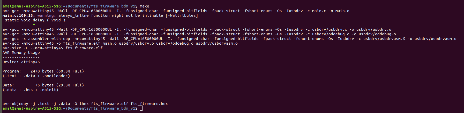
The make file of the firmware assumes that you are going to use a programmer in the usbtiny category (another fab ISP). If you’re using a different programmer, first figure out what avrdude (the programming software) calls it.
Edit the file called Makefile. It is important to use a text editor intended for programmers. Near the top of the file, find the line that says:
PROGRAMMER ?= usbtiny
(Ref:archive.fabacademy.org/2018/labs/fablabkochi/students/jogin-francis/Images/week_5/burn/lsusb.png)
(8)Then used make command to initialize the programming operation by cheking command in terminal and ensure the device is identified
lssusb
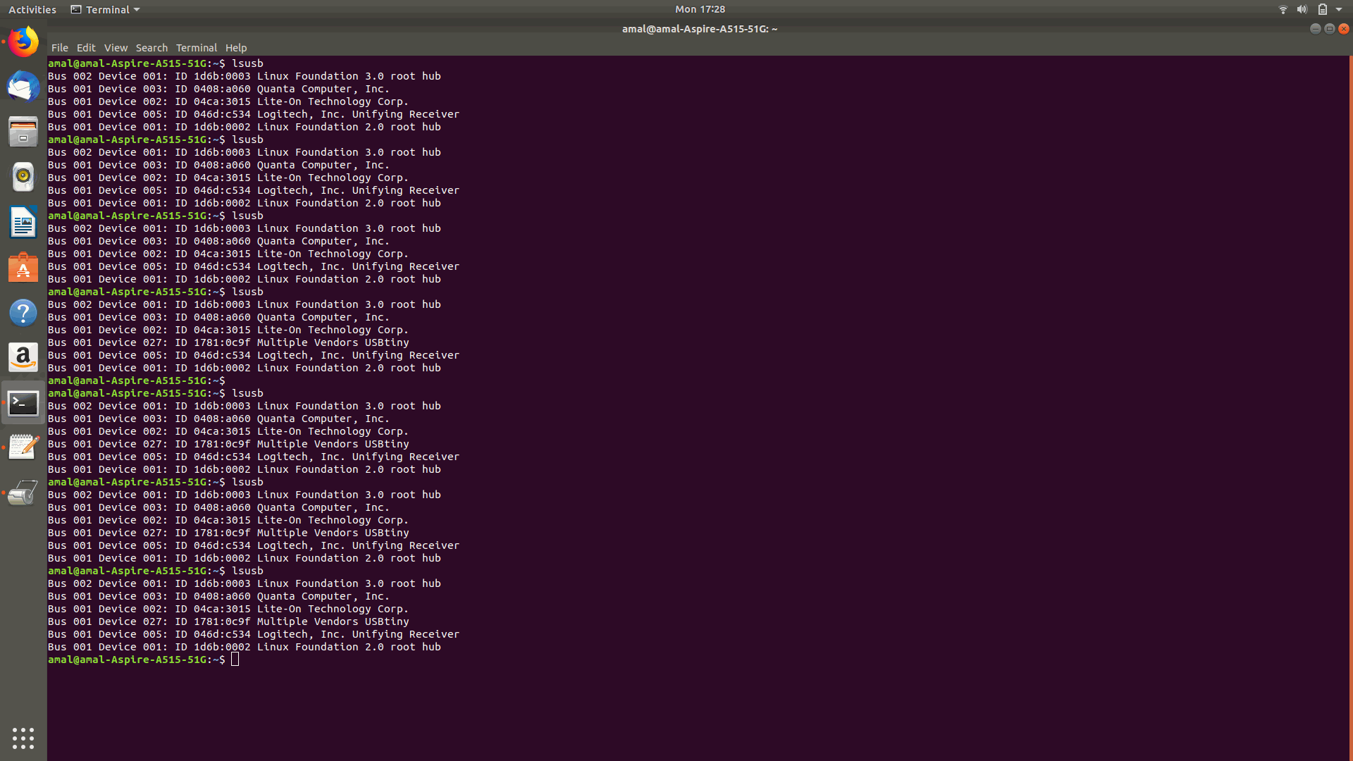
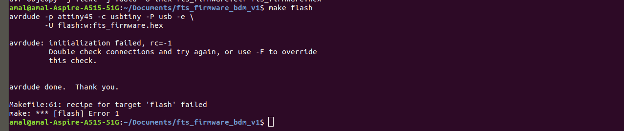
(9)Then used Make flash to flash the memory and some problem occurs and showed the rc-1.This time the problem was with usb plug as if the the usb head was not correctly attached to the usb drive.So I holded up the ISP Programmer upright to recoganize it and again i have given the command
make flash
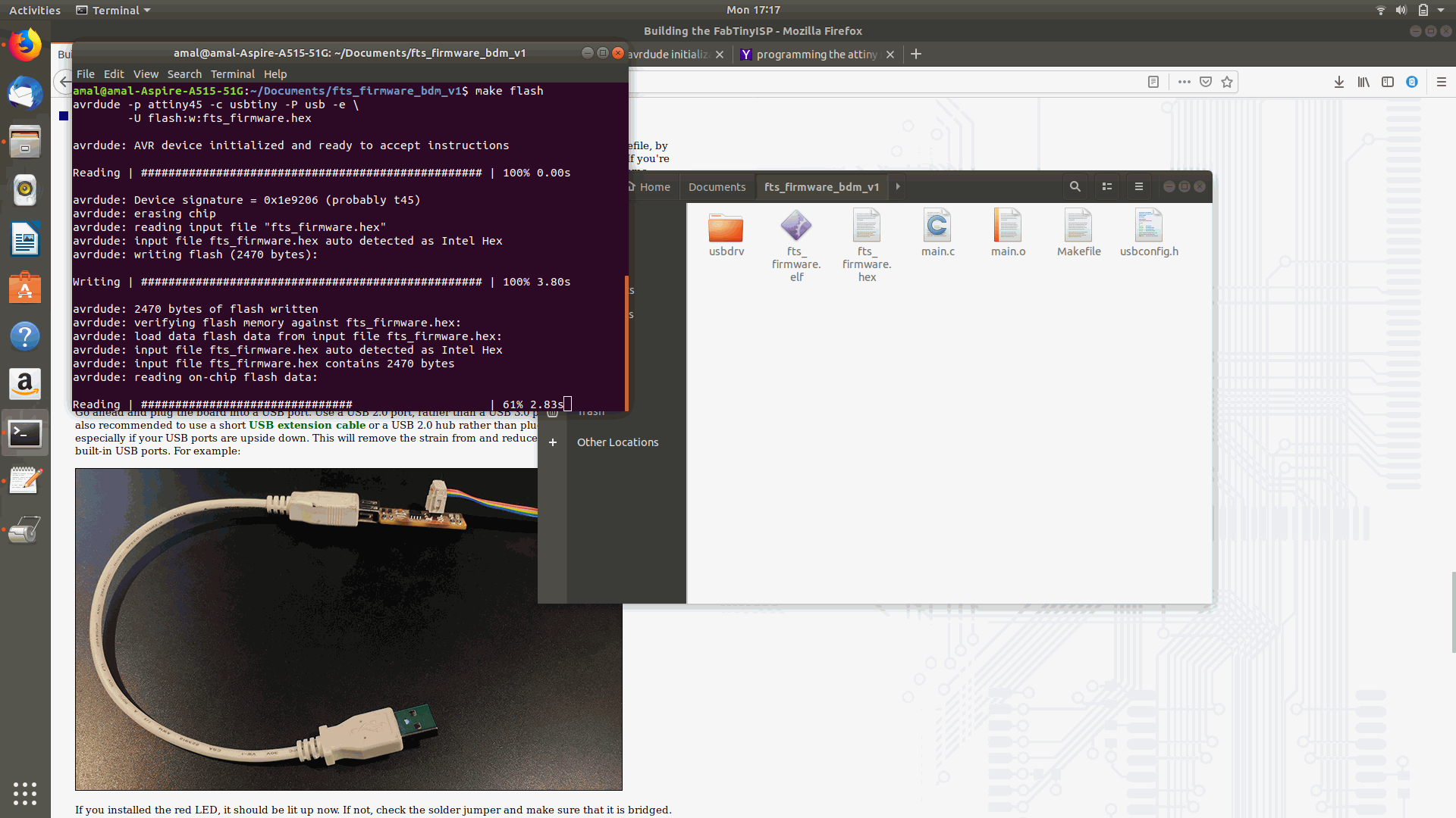
and this time the memory was flashed
(10)Again it showed the same message and then it was understood that middle terminal that is connected to the controller was not properly touching the port properly.
(11) Then I planned to make a support with layers of vinyl underneath the usb connection.
(12)After that it was correctly fitted.
(13)After that the programmer was directly plugged into the PC USB port.
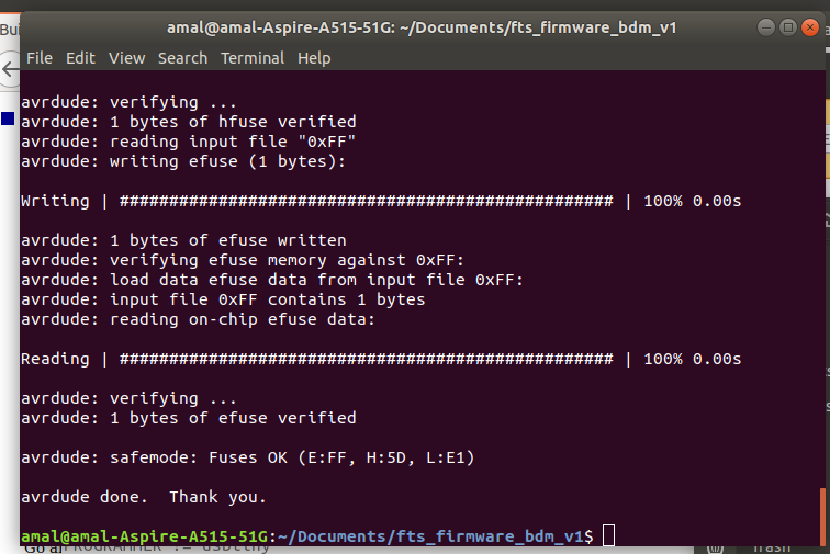
(14)Then I again checked out by using the lsusb command and it was detected and to set up all of the fuses except the one that disables the reset pin the command was given.
make fuses
(15) Then to change the bit that will turn the ATtiny45’s reset pin into a GPIO pin.This will disable our ability to reprogram this ATtiny45 in the future, hence make sure everything is working before doing this. Connect your ISP programmer to your board one more time, and in the Terminal run
make rstdisbl.
By this the Electronics Production assignment was finished.
FILES
The Files were taken from academy site