6. 3D Scanning and printing
The week comprises about 3 activities
1)Group Assignment
The group assignment was to test design rules for your printer.
Our instructor has given some ideas about the 3d machines available in fab lab Trivandrum.
The lab was having 3 Printers namely
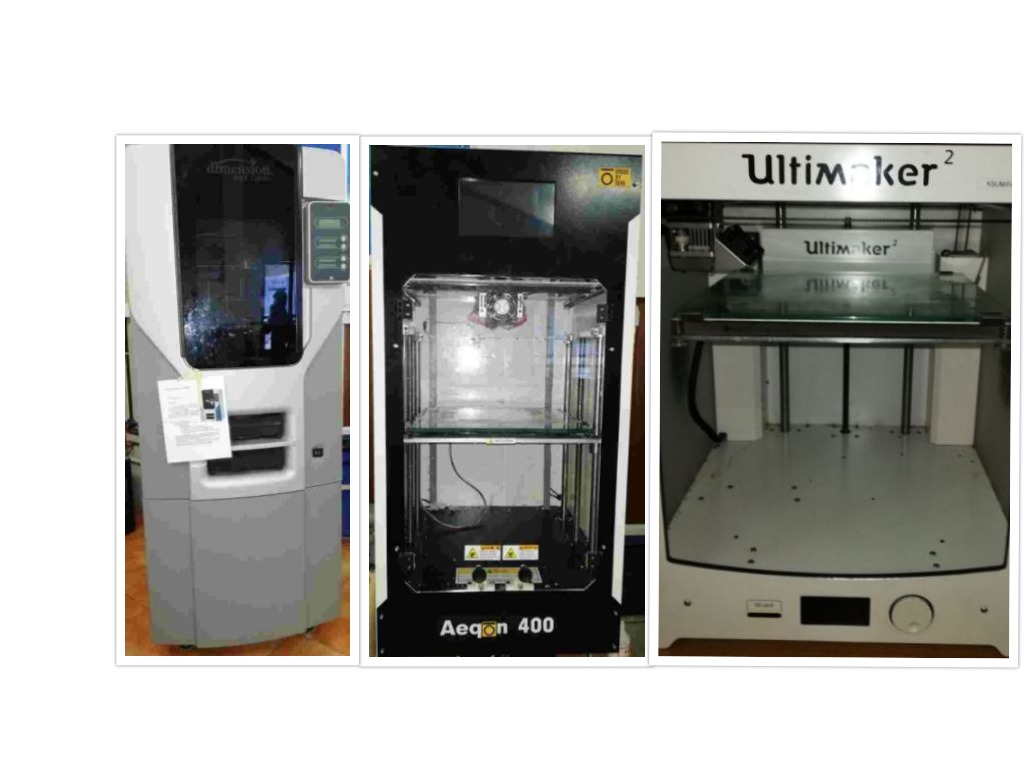
1)Dimension SST1200es
Which is very good in printing ABS with PLA Support.The instructor explained about loading plan and abs in the machine and the final technique of reducing the supported pla by dipping it in a chemical.
2)Aeqon 400
Series which is good at 3d printing using ABS material.
3)ULTIMAKER 2
Which is a popular machine in 3d printing especially PLA and I planned to make my experimental designs in PLA.
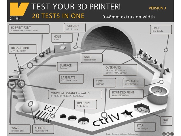
Then for doing the group project I downloaded a machine test stl file
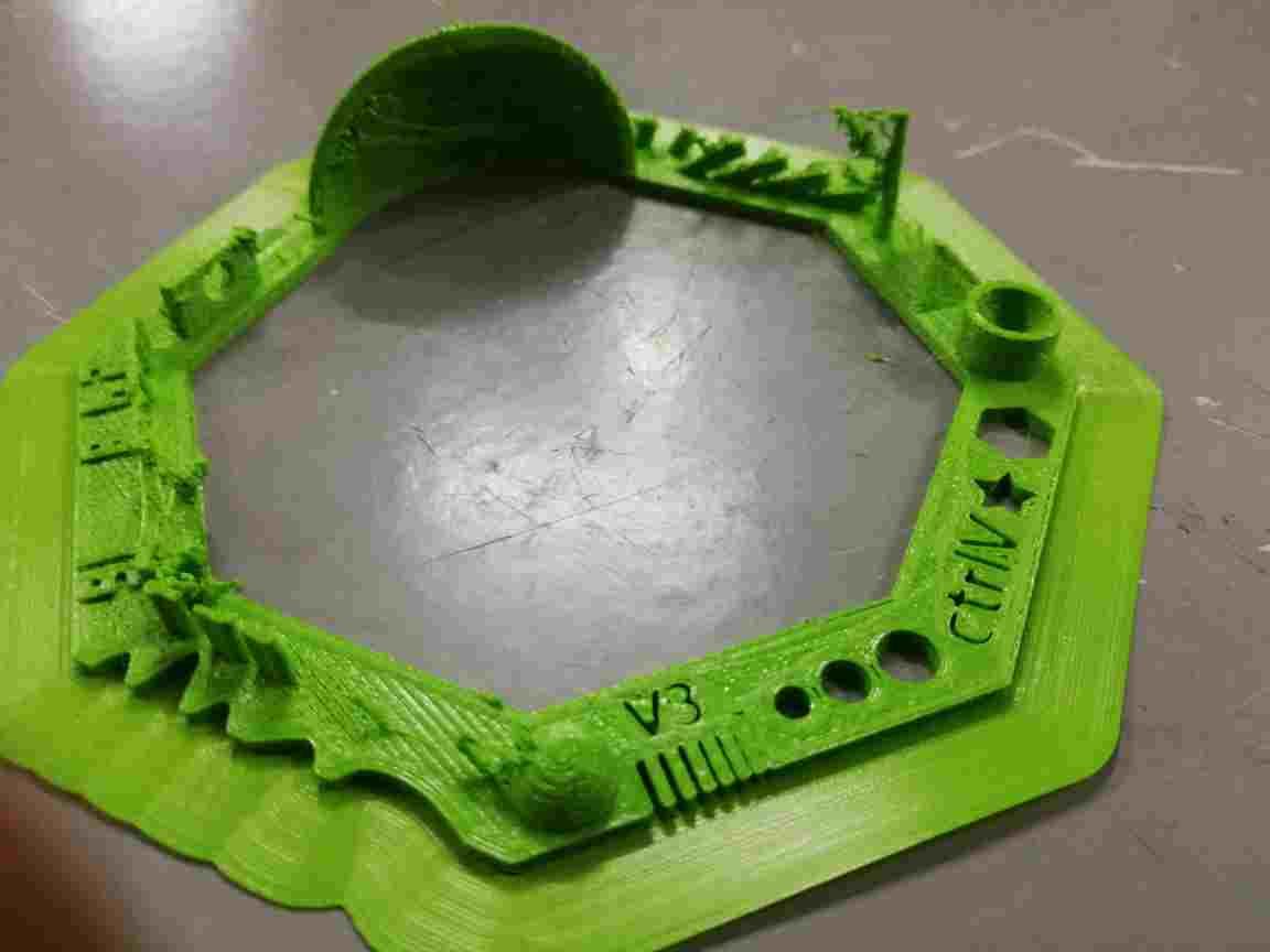
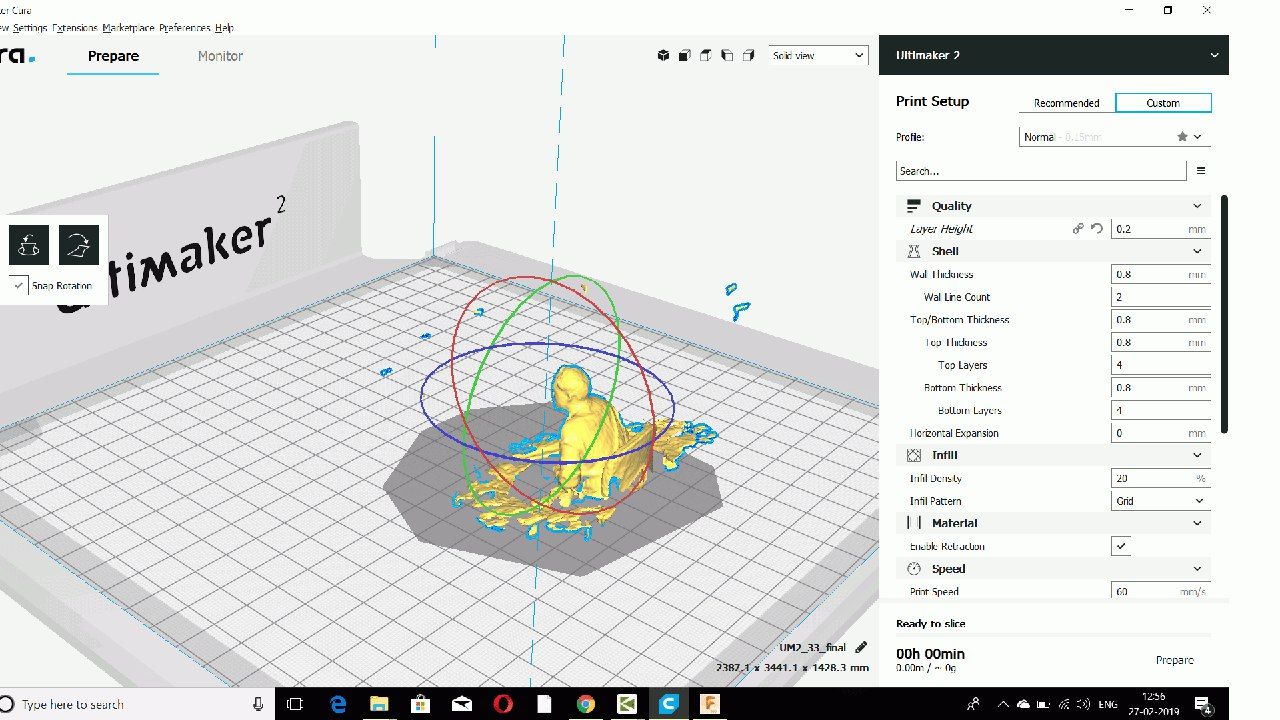
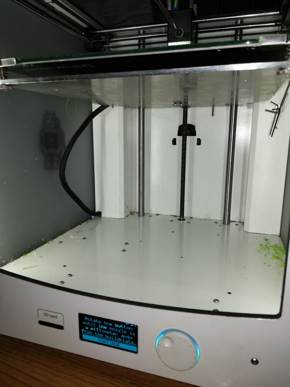
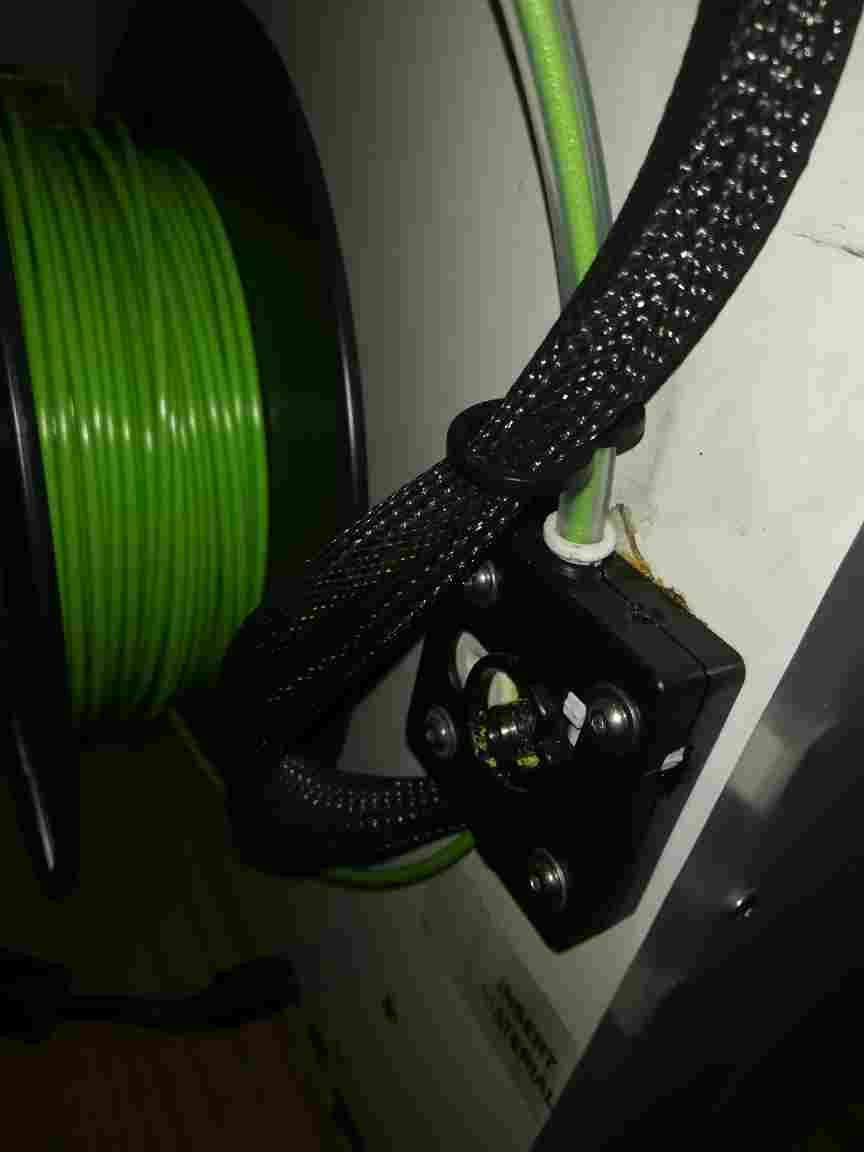
The First thing we did was to clean the base plate and removed the existing pla from ultimaker 2 which was in the lab and inserted a PLA spool of my favourite GREEN Colour.
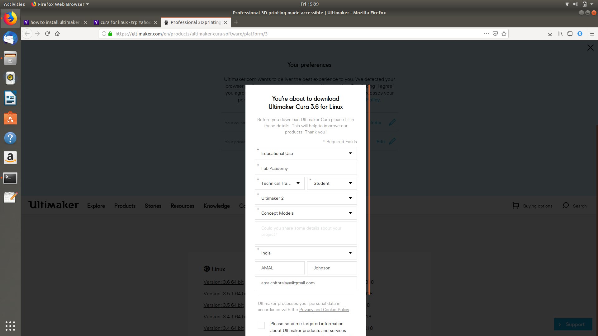
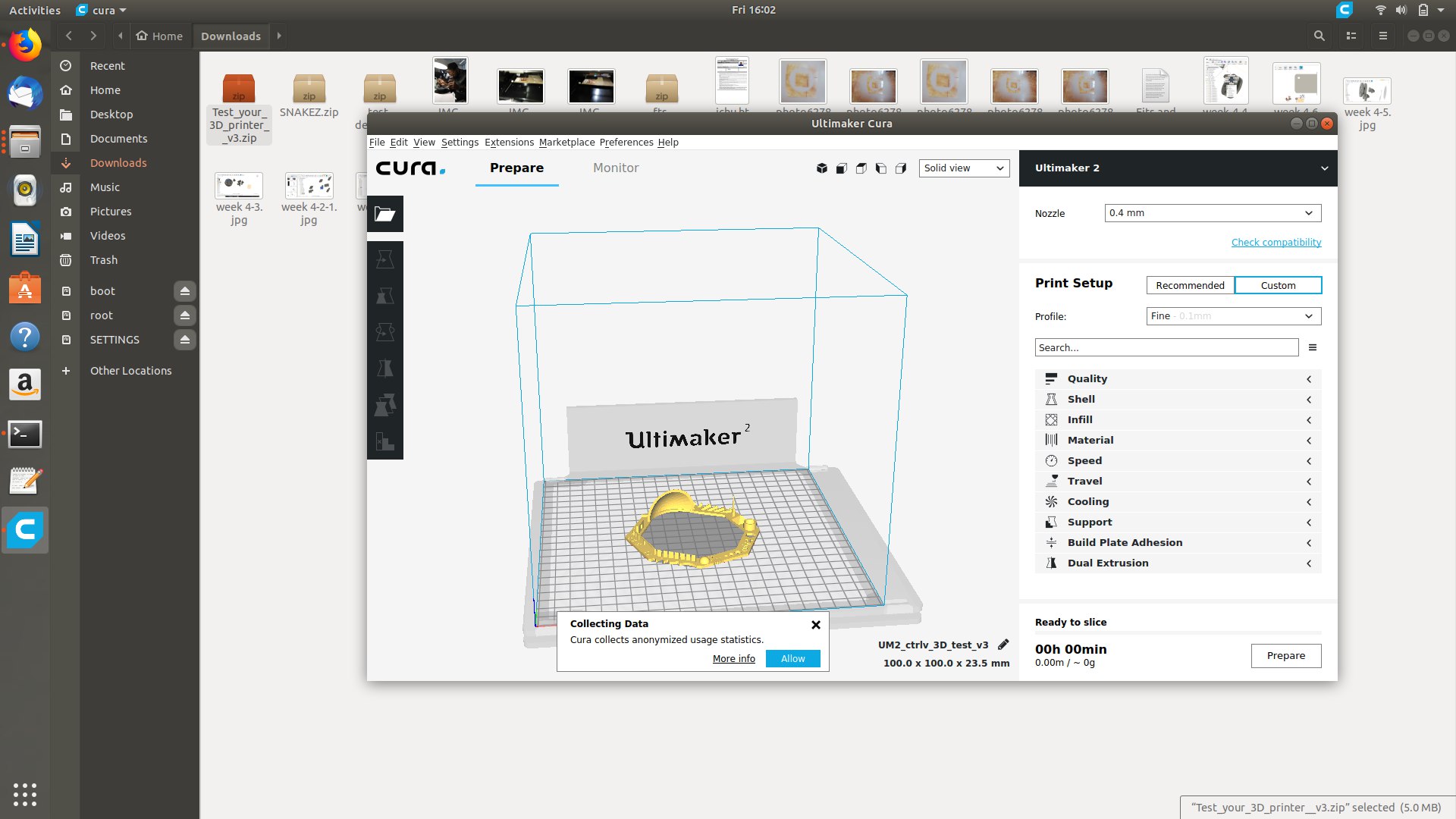
Then for making a test design we have downloaded a STL file from thigngivers.com and converted into a gcode by ultimaker cura software and the print was studied by making the following observations.
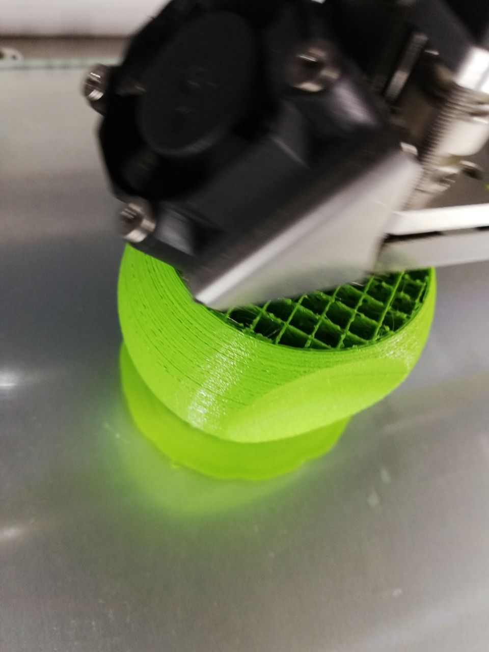
1.The small Warp Shaped Structure was slightly ruptured at the top because extruder went slightly shaky but in overall it was 90percentage success.
These were the parameters that was set

Then I Checked the infill,material layering,support material density etc.
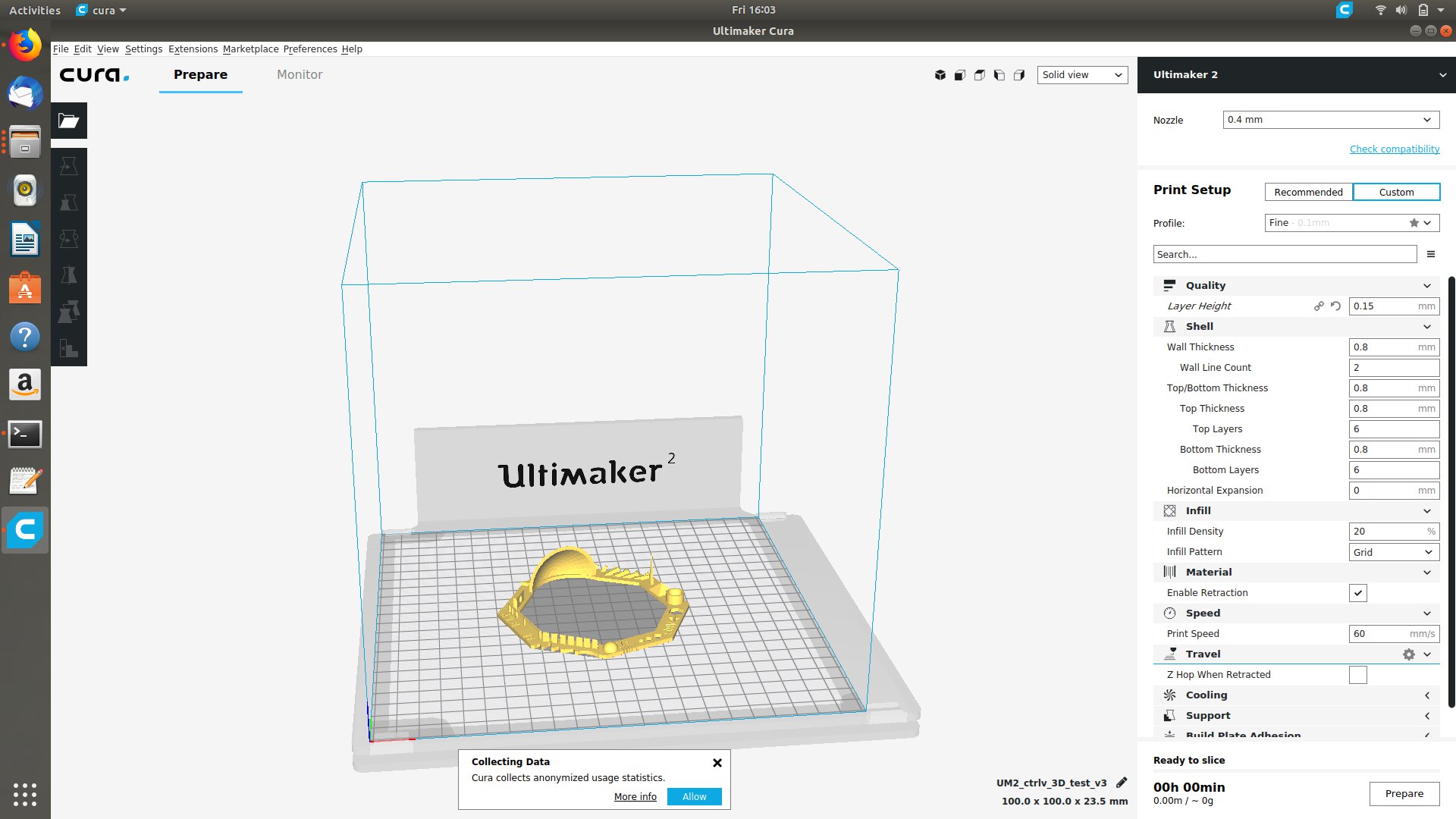
Then keep it for slicing
2.The material flow was deposited during the transport of extruder from one position to another.
3.The Spike structured was seem to be incomplete and the excess amount of pla was deposited.
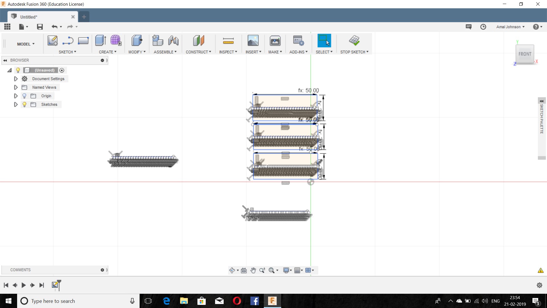
4.The overhanging layer of 25/30/40/45/50/55/60/65/70 degrees were formed in it and was formed without any support and it was having bit excess amount of pla in int bt it was fine.
5.The Bridge structure was not fully formed with 1 mm thickness and it was understood the layer will be strong enough when it will be having more than 1 layer in it.
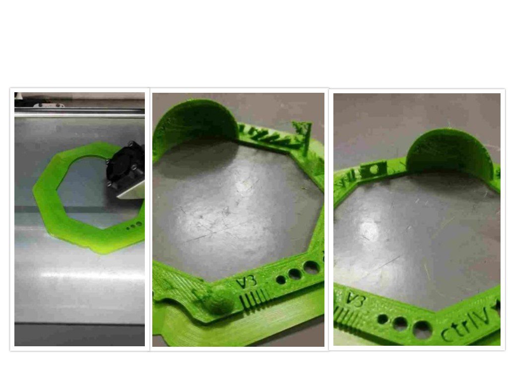
6.The rund print was well printed with 5/4/3 mm radius and from that the offset was determined as 0.6 mm by using a digital vernier.
7.The Nut,star design,writings and hole were very well printed without any cologg.
8.Then the Excess support material was removed using a chisel sandpaper.
2)Designing of a model individually
1)Primarily I Planned to make stencil which can make the desired shape of the same size which can be used for cutting and the partial design were made and then realized that it can be easily cut by using a laser machine and not meeting the required assignment criteria,So I planned to make another design .
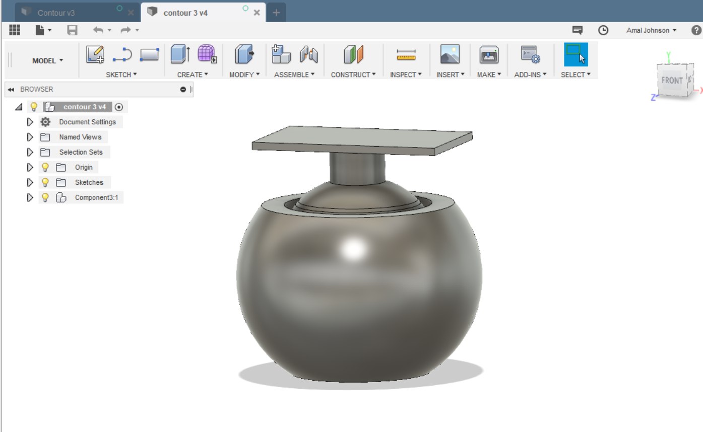
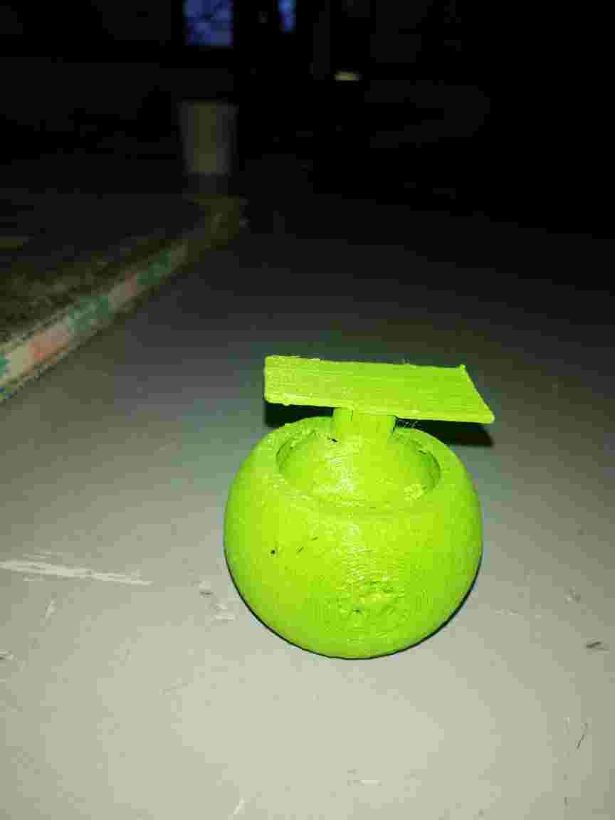
Making of a ball and socket round table
2)So I planned to make a design that is inscribed on another design ,which can be easily usable and I arrived at a conclusion to make a portable round table that can be used for sticking the PCB board so that it can be used while soldering.As if I was suffering from a lack of turntable last week for soldering purposes,I stick rigid on the purpose.
3)So I planned to make a ball and socket joint design wit a plate at the top.
4)I Designed it using FUSION 360 And the following errors occurred
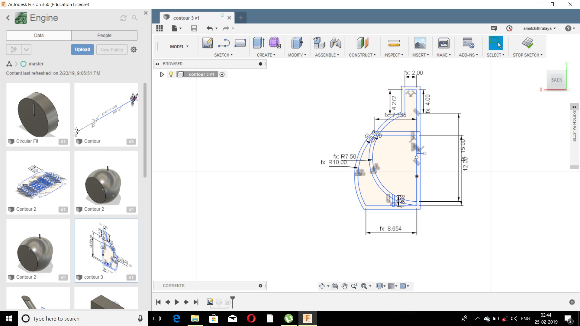
(i)I planned to make a 2D sketch and extrude it but the estimated diagram was not spherical so i planned to complete it with revolve option
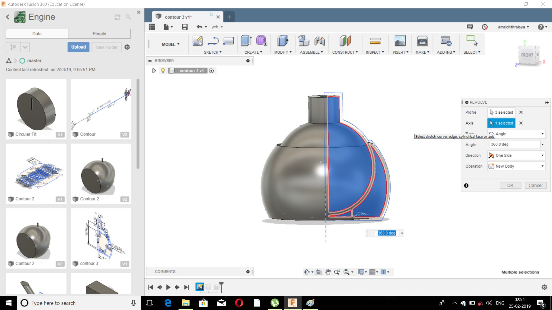
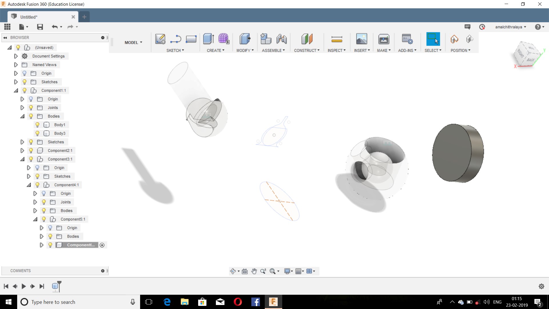
(ii)I drewen the figure with 3 Components and managed to join, but the problem was while saving it to STL.Generally Each component is saved to stl and not bodies.Then I managed to make it one component and i planned to draw the entire Sketch once again making it a single component and revolved it and then saved to stl with 0.4 as offset outside but its shown that the component 2 was not joined since one extra body was formed and then went back to the sketch and rectified it.
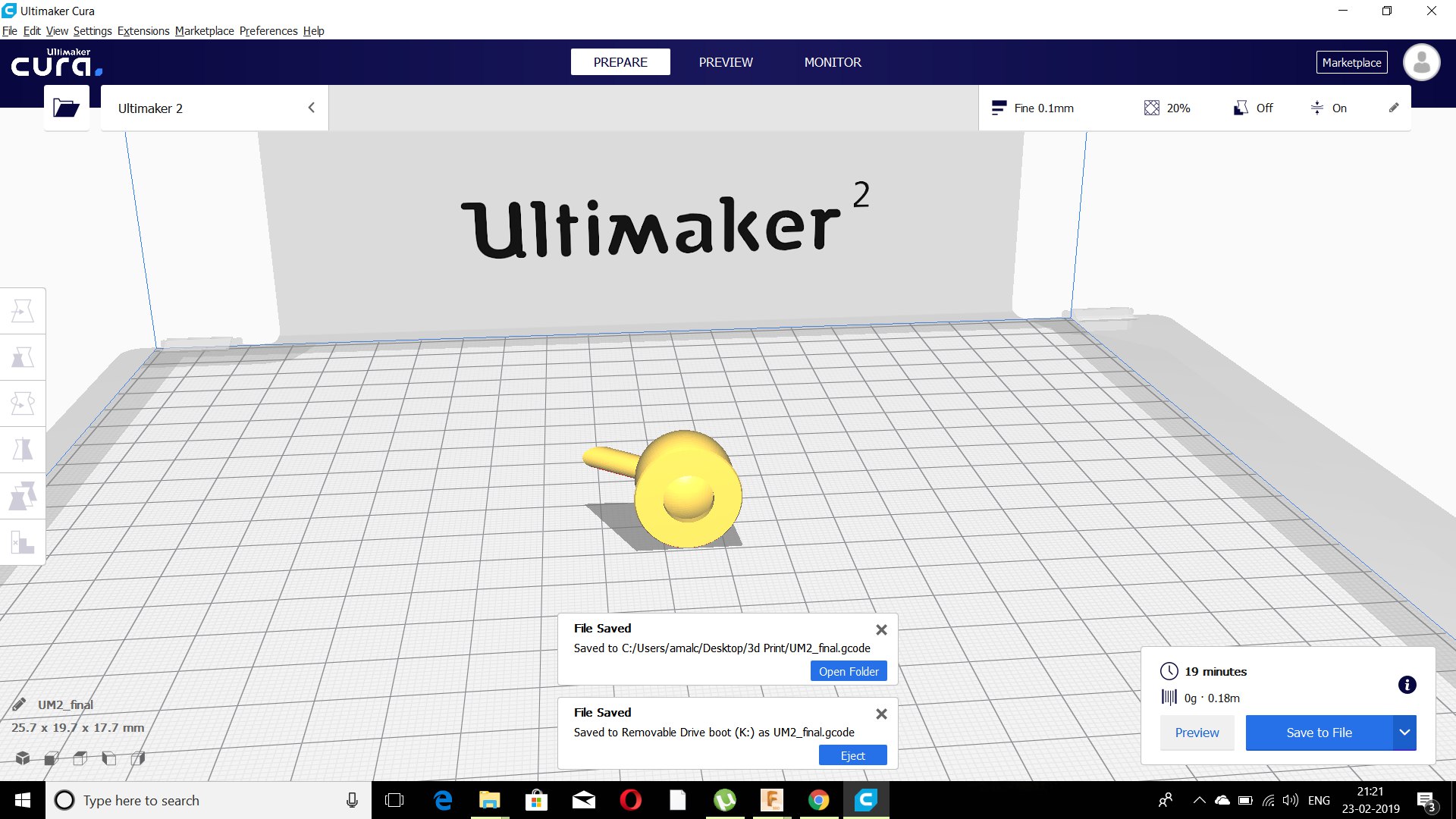
(iii)By using the Cura Software i converted it into Gcode and inserted in the Ultimaker for test Print of 30 mins.But the 30 mins print time was felt wrong even though I continued for the result.
(iv)The test was a failure and found out that the support was very firm and the components were immovable.It was found that the offset given was very less and planned to check it with the test designed estimated and from that I referred that the estimated value was more than 0.5 mm offset.

(V)Since the diagram was parametric it was very easy to edit and i made the offset as 1 mm and saved to STL format.
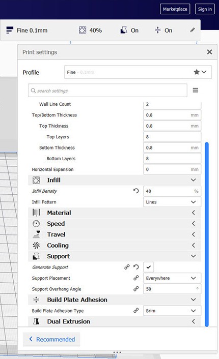
(vi)Then I Planned to Scale the design using CURA and other features like Setting Speed,Support density,Animation of the print material by making it layers and the Coordinate position for making the support minimum were studied so that the operation time can be reduced and the parameters were added.
(Vii)Then I Sliced the file into G Code and sved to the memory card which showed a 4 hours of printing time.
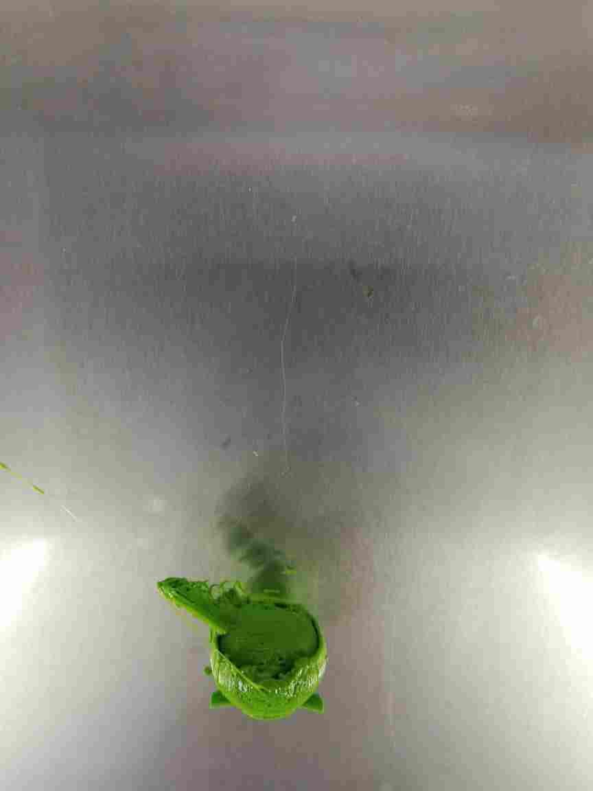
(Ix)Then I Printed the design but an error occurred while printing i.e the material was not coming through the extruder and thus some of the layers were not printed and i manged to pause the printing and checked the problem.
(x)The problem was identified as the PLA go stuck with the extruder and the servo motor at the back side of the printer was not enable to push the material.
(xi)Then by using the advance,move option in ultimaker,the extruder were raised up to 210 degrees and by using the round button the material was moved downwards.
(xii)Then the estimated time left for printing was shown as 15 mins and I managed to complete the process.
(xiii)The material was printing without the support in air so that the print was ruptured.
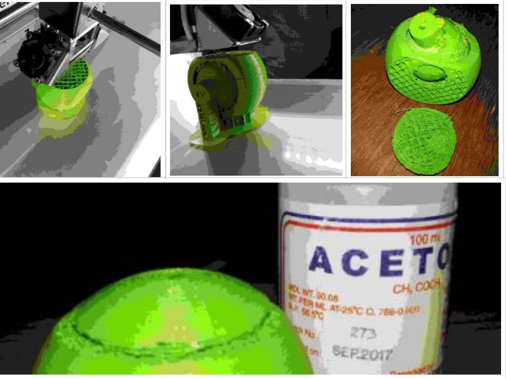
(xiv)The after the printing process I Glued the parts by using an Acetone and the test print were done and I made a table top with cardboard manually.
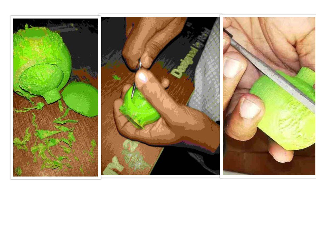
(Xv)Then for testing the strength of the PLA i thrown the print towards ground and it was broken and then i again fixed it with acetone.
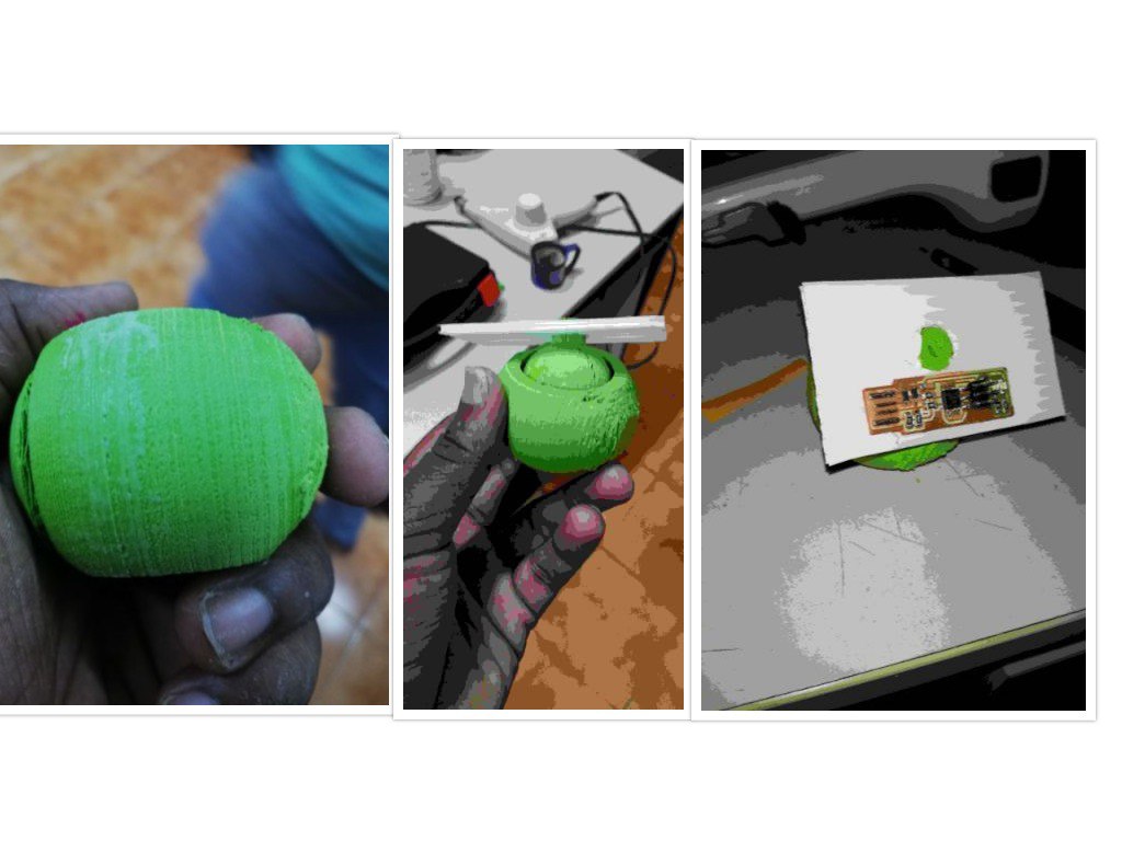
(xvi)Then I planned to edit the design by making a table surface at the top and to print the design.
3)3D Scanning
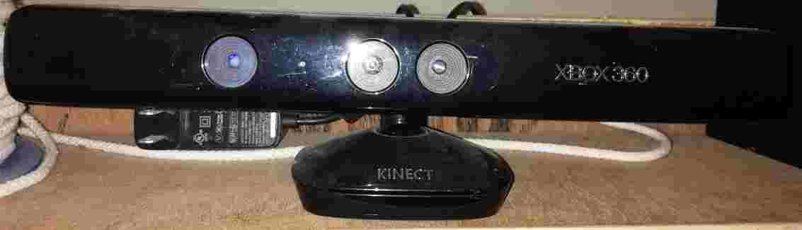
For 3D Scanning,the available scanning camera was xbox
The selected driver software was kscan
Then by applying the light source I scanned my own image using 6 seconds timer in the kscan software and almost 16 images was captured and unfortunately the image was ruptured and the pictures were not combined and it was not able to stich and it was noted the light source provided was uneven.

then I managed to repeat the process and the light source was placed nearer to the Xbox camera and the following process
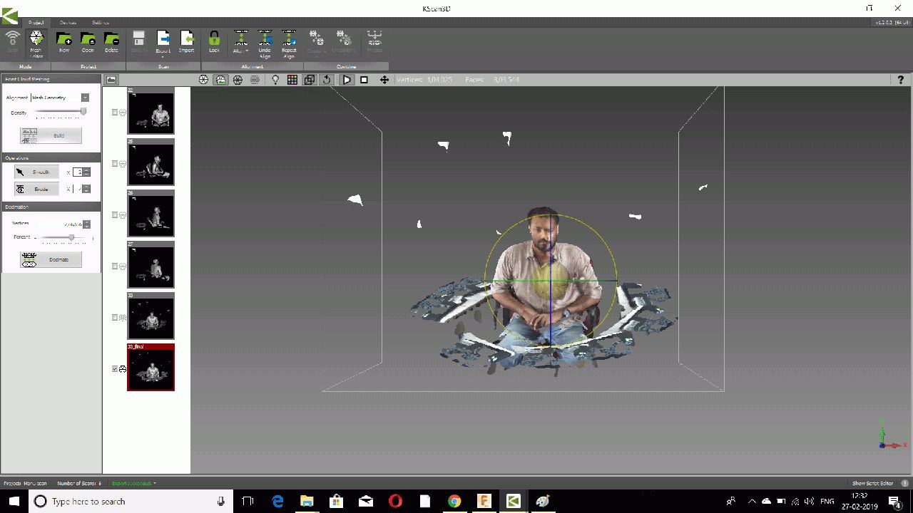
and this time the image was combined fine but some disturbances was formed in the scanned image and I exported the file in STL format and opened in Cura software and it was comparatively a bigger image and managed to scale it down.After that the STL was sliced and turned into a Gcode