8. Computer controlled machining
This week was about designing something in the software and doing the corresponding operation in computer controlled numerical machine.
Through the week
The assignment comprises about
1.The Group project was about to test the runout,alignment,speeds, feeds and toolpath of the machine.
2.Designing something in the software
3.Executing the design in CNC machine
Execution
1.The Group project was about finding the offset and cutting depth.
For the group project the main objective was to test the runout,alignment,speeds, feeds and toolpath of the machine.
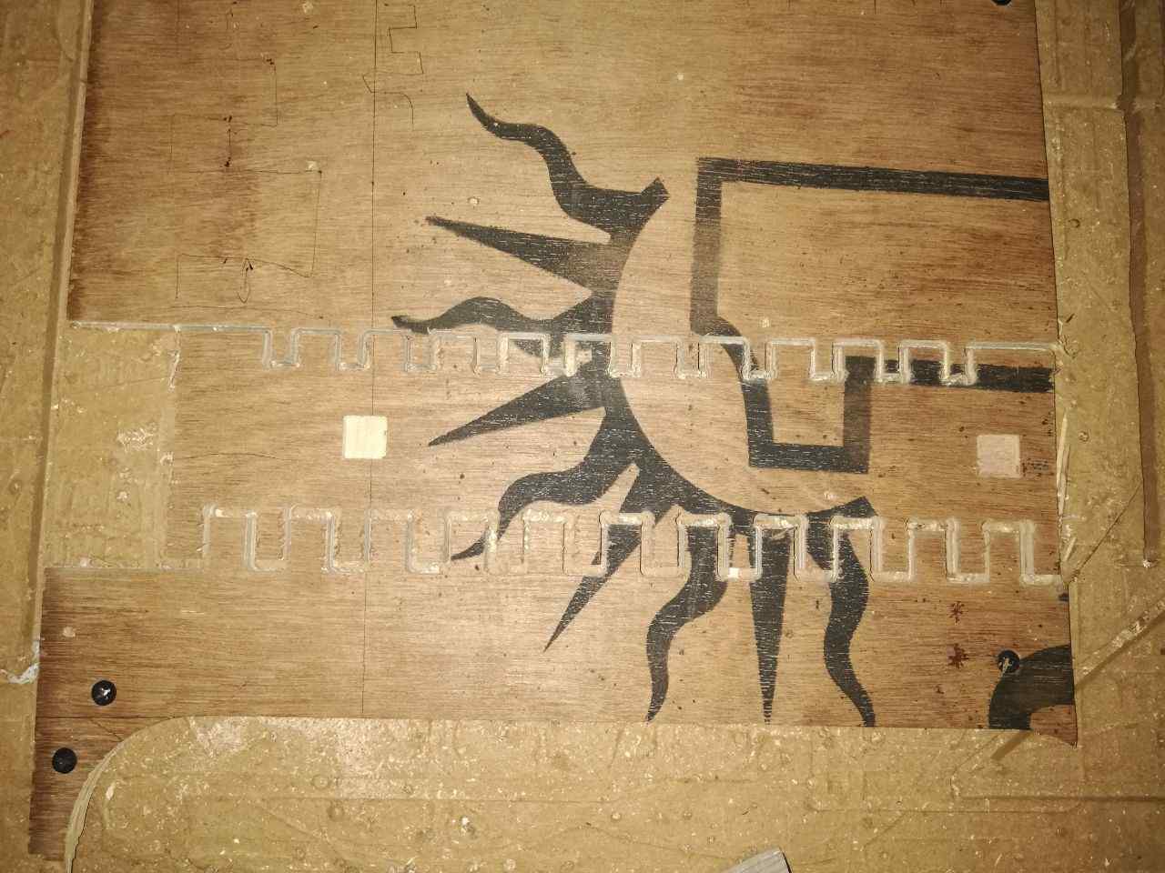
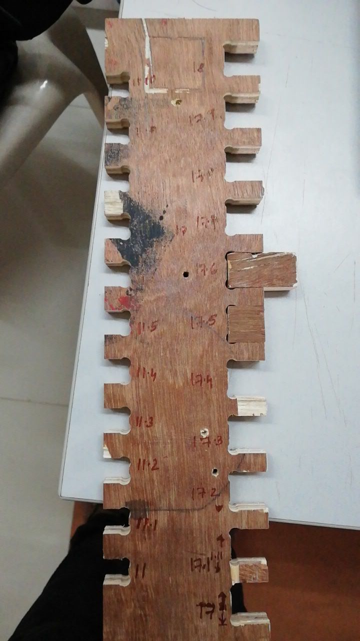
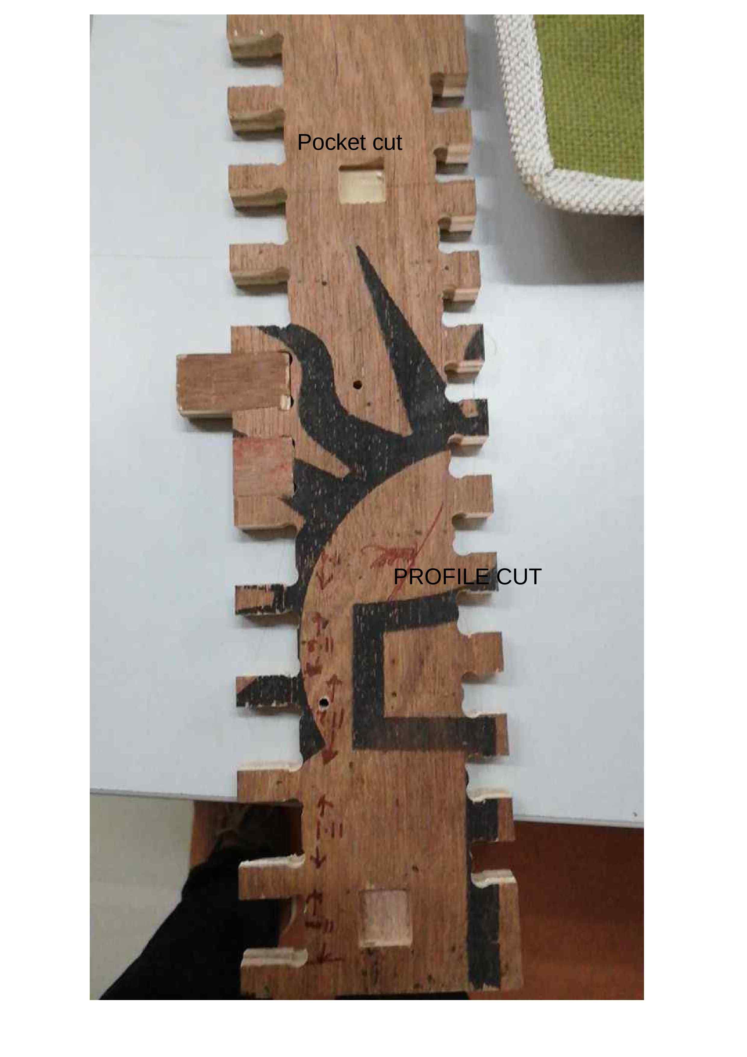
For estimating the above mentioned details we planned to make a comb like structure varying the female part of the fit design from 11mm thickness to 12 mm thickness by arranging it in 1mm increasing order thickness and then we cut a male part of 12mm thickness and then found out that it fits perfectly on 11.6 and by that it was estimated that the offset was 0.6mm and this was estimated as profile cut
Then the pocket cut was selected with 5 mm thickness and it consist of two types and the upcut and the down cut and both of the cuts was studied and from that it was observed that the beginning of the cut was very much precise and smooth by using the upcut and while using the downcut we will get a smoothened end.
After checking on the internet it was founded that 11000 was the spindle speed for mdf and plywoods.
2.Designing something in the software
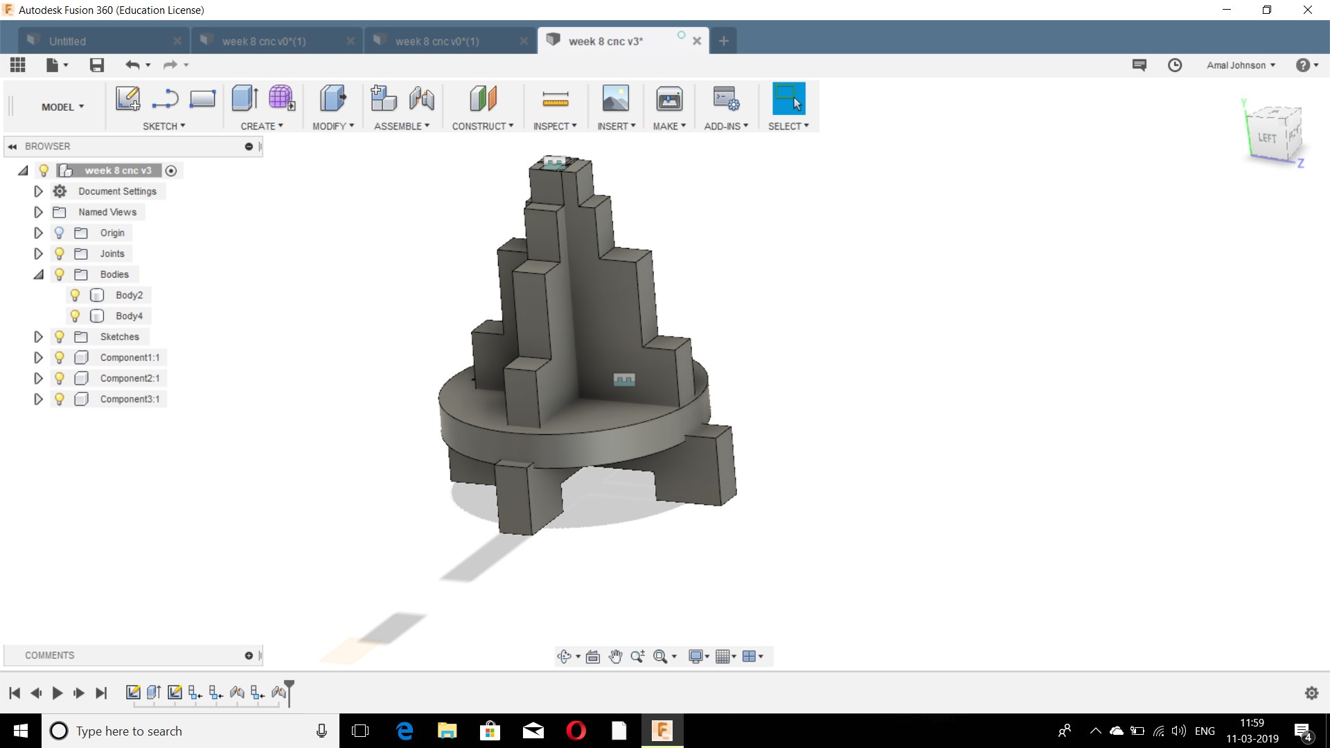
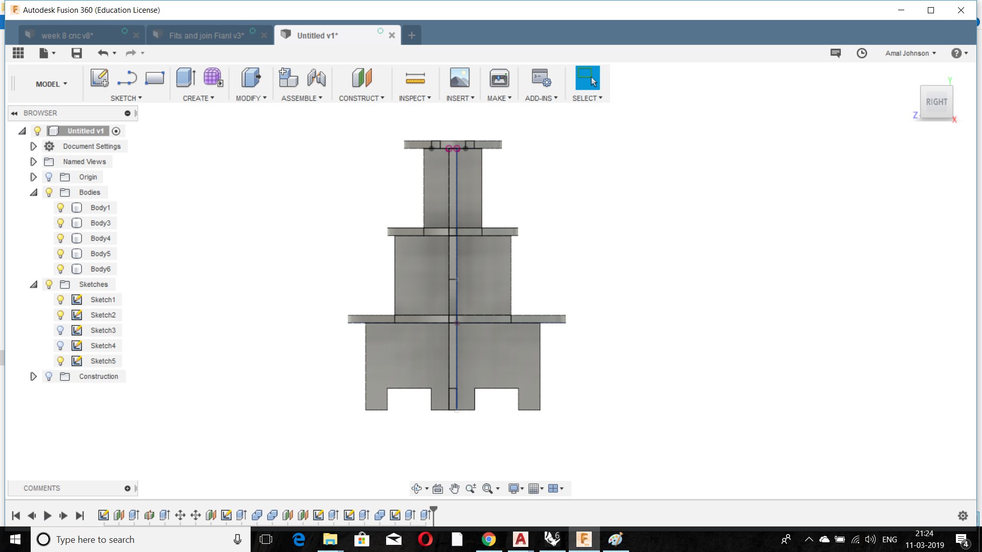
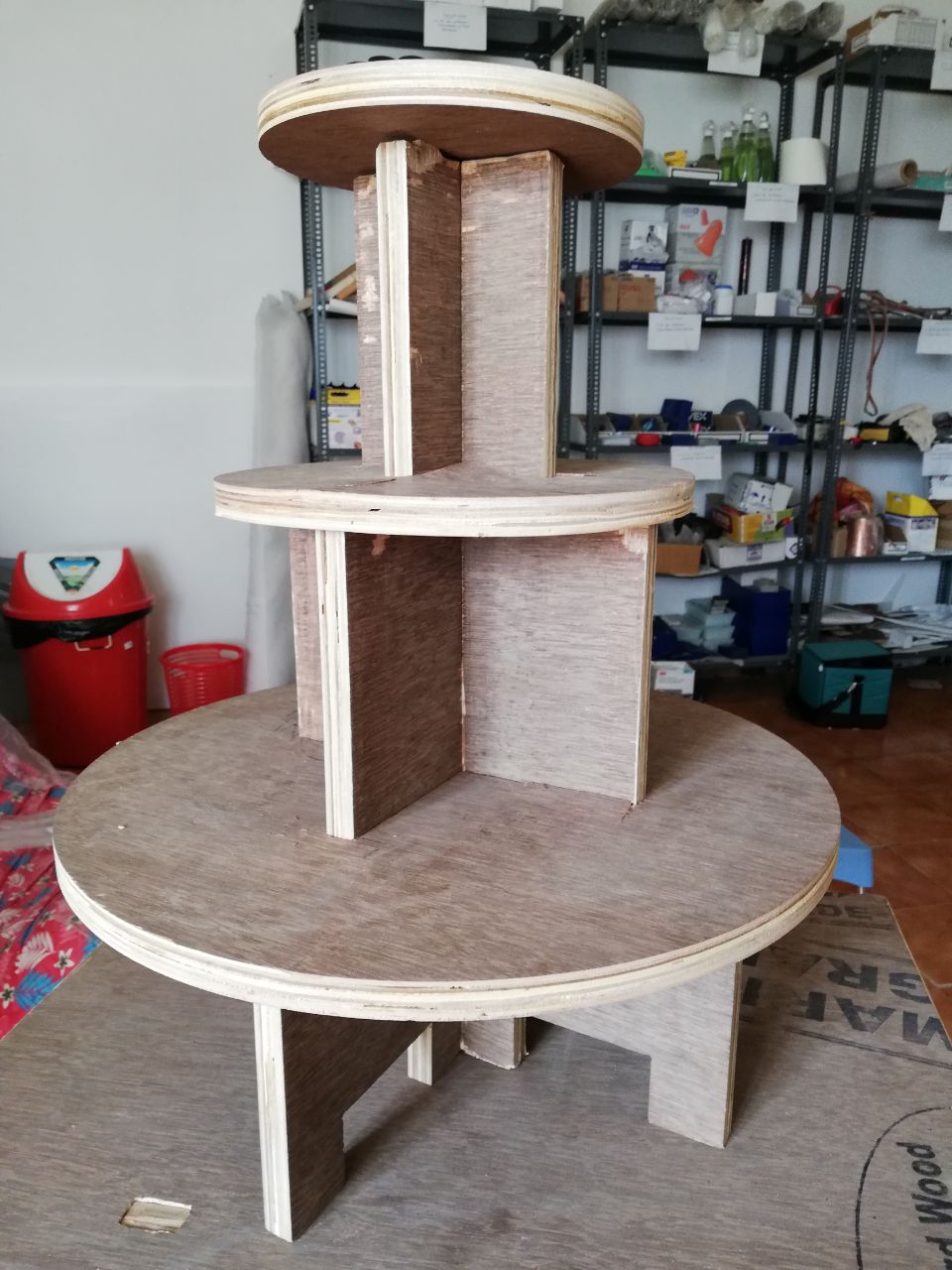
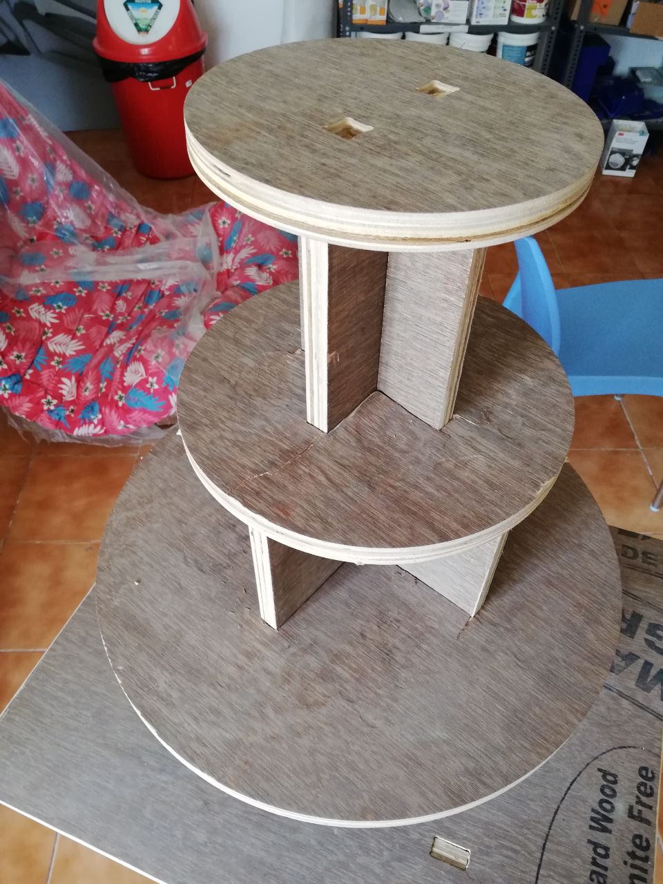
(i) I planned to make a 3 floored shelf for placing the lamp in my home.
(ii) So I referred to the design of a cupcake shelf from amazon.com.
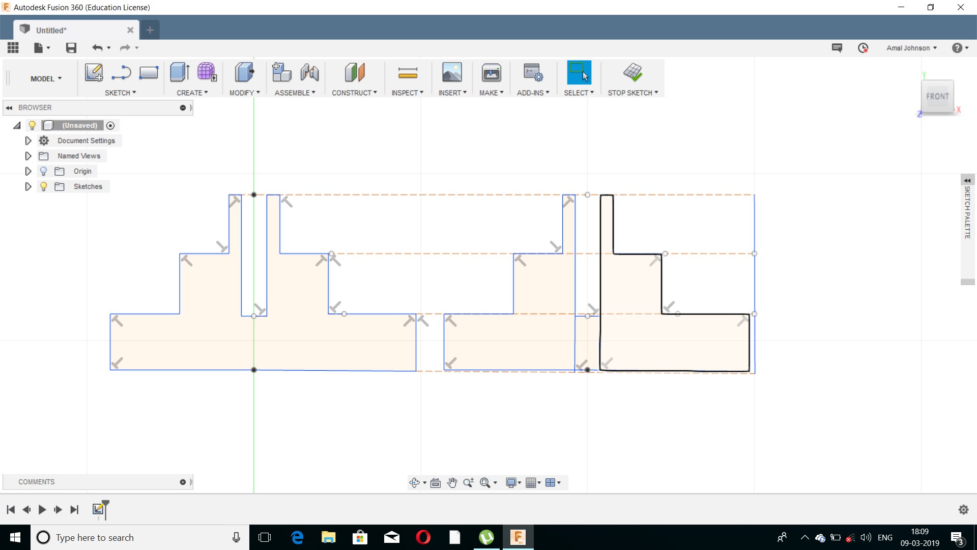
(iii) I planned to make the sketch in Fusion 360.
(iv)Since I was a beginner in fusion 360 and the objective i planned to make it a simple design ,even though many errors occurred during the process.
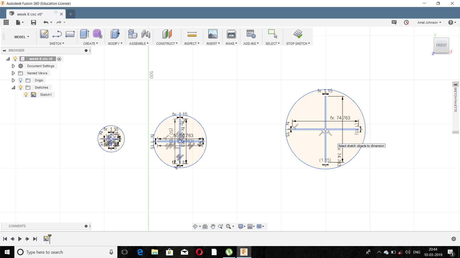
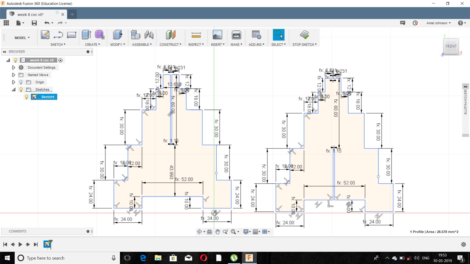
(v) The design sketch comprises about 2 circular plate and a fit and a,de the diagram with estimated dimensions as i required and applied the parametres to it.
(vi)But all the parameters went wrong and the major error I made was I estimated too many parameters unnecessarily.
(vi)So I Planned to redraw the estimated design with more precise dimensions but I felt something was wrong somewhere while applying the join command since my motive was to draw an assembled design.
(vii)After that I asked about the procedure of drawing in fusion 360 and my instructor has given me a clear cut view about fusion 360 and explained to me the concept of making the drawing in different plane and projecting of the object and drawing it in different planes.
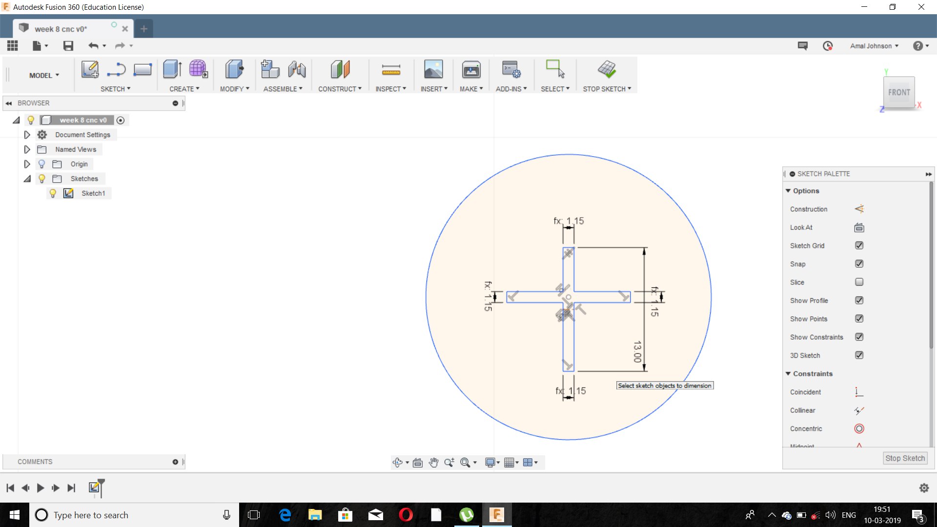
(viii) And again I planned it redraw it again from the beginning by giving only two parameters ie. length and thickness and estimated the design.
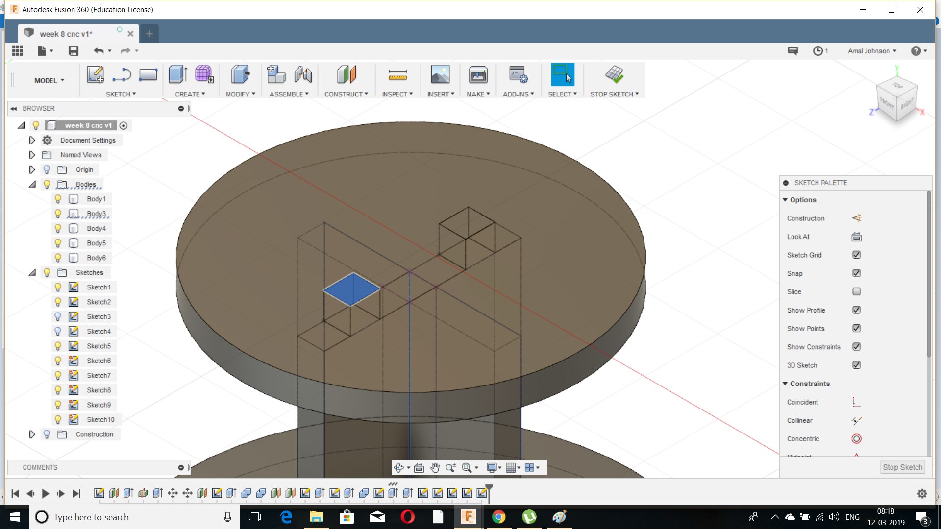
 (ix)While designing I learned to use the exact use of parameters and the usage of constructing a plane ad to draw the parts in it.
(x)I sketched the estimated design of the bottom part of the shelfa and I extruded it and then I rotated the same sketch and extruded the male part of the fit design.
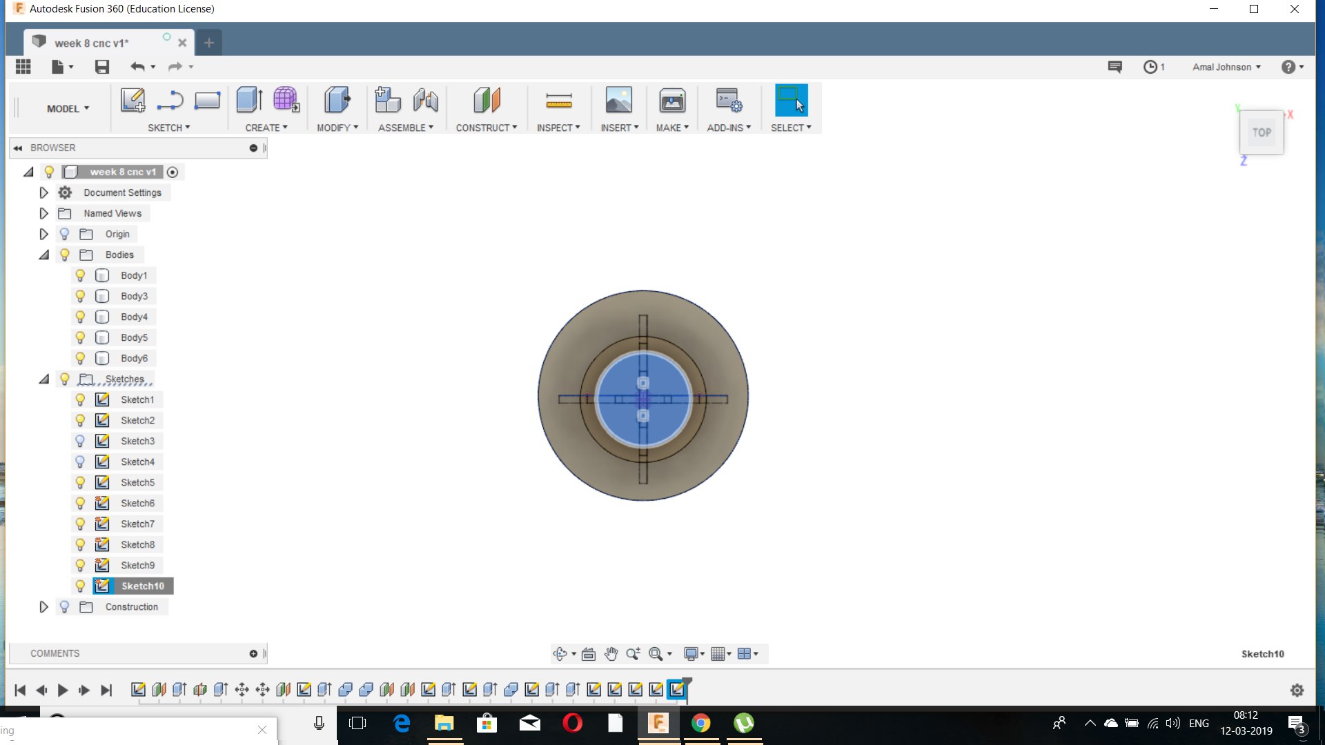
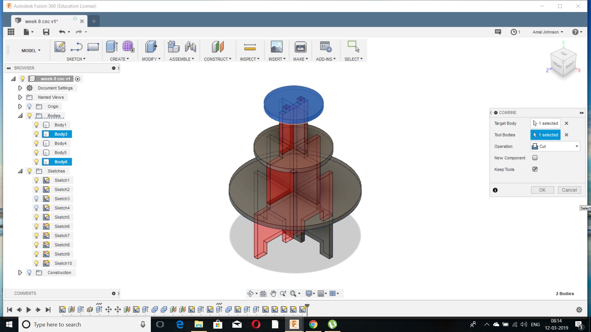 (xi)Then by using the constructing plane I drawn the circle to it and extruded it and then by using the combine option i selected the cut by making the circle and the object to be cut and the fit design as a tool to cut the circle.
(xii)After finishing the design I Exported the sketches into DXF format and verified using AUTOCAD.
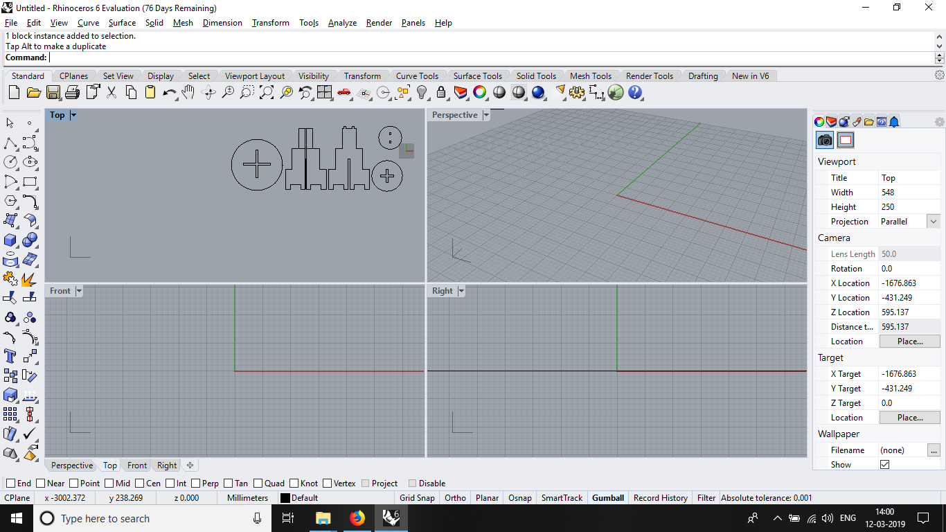
(xiii)Then I downloaded the Rhinoceros and V carv for further process.
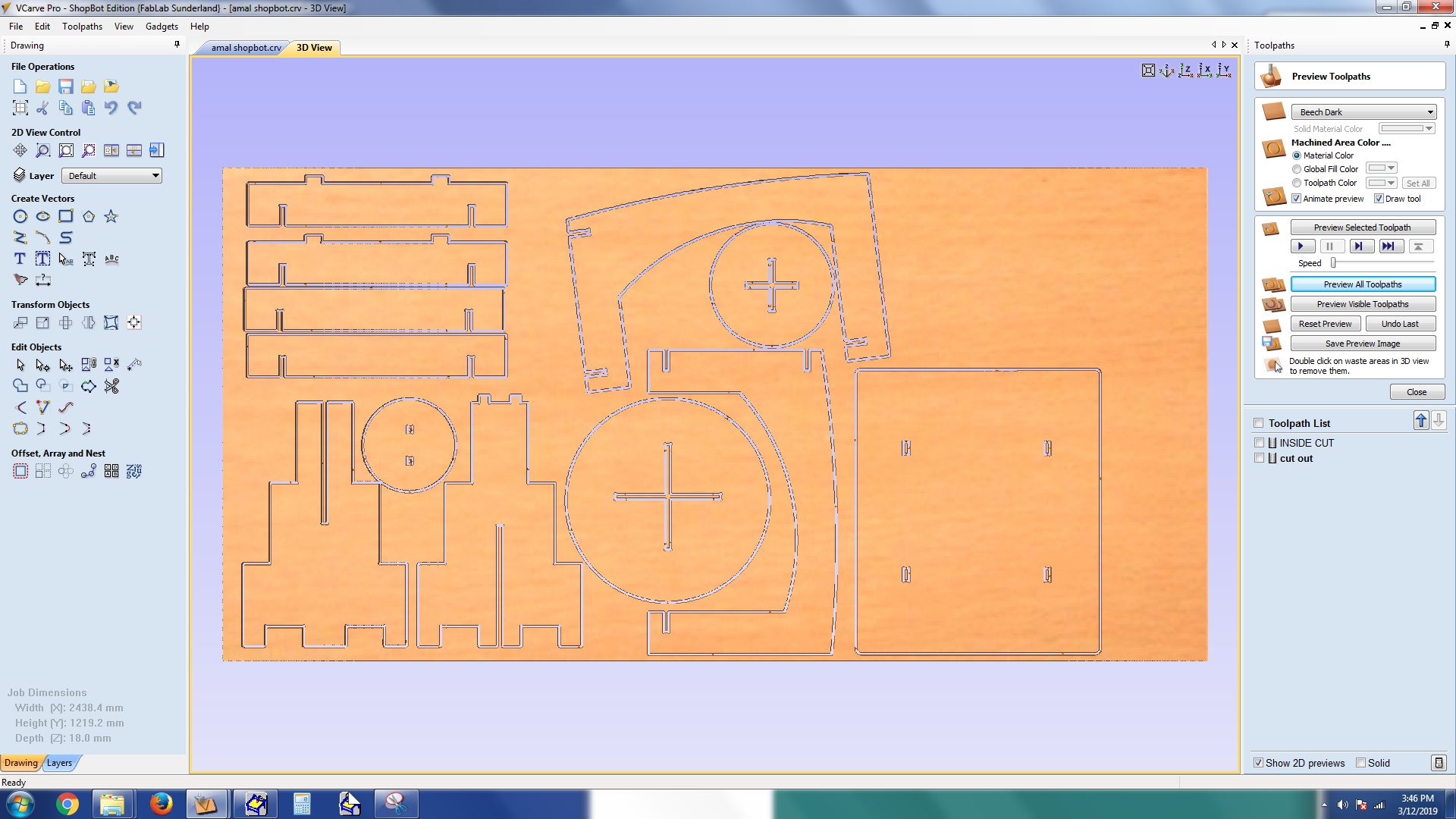
(ivx) Then I arranged the sketches according to the minimum usage of material and the saved and exported to the v carv.
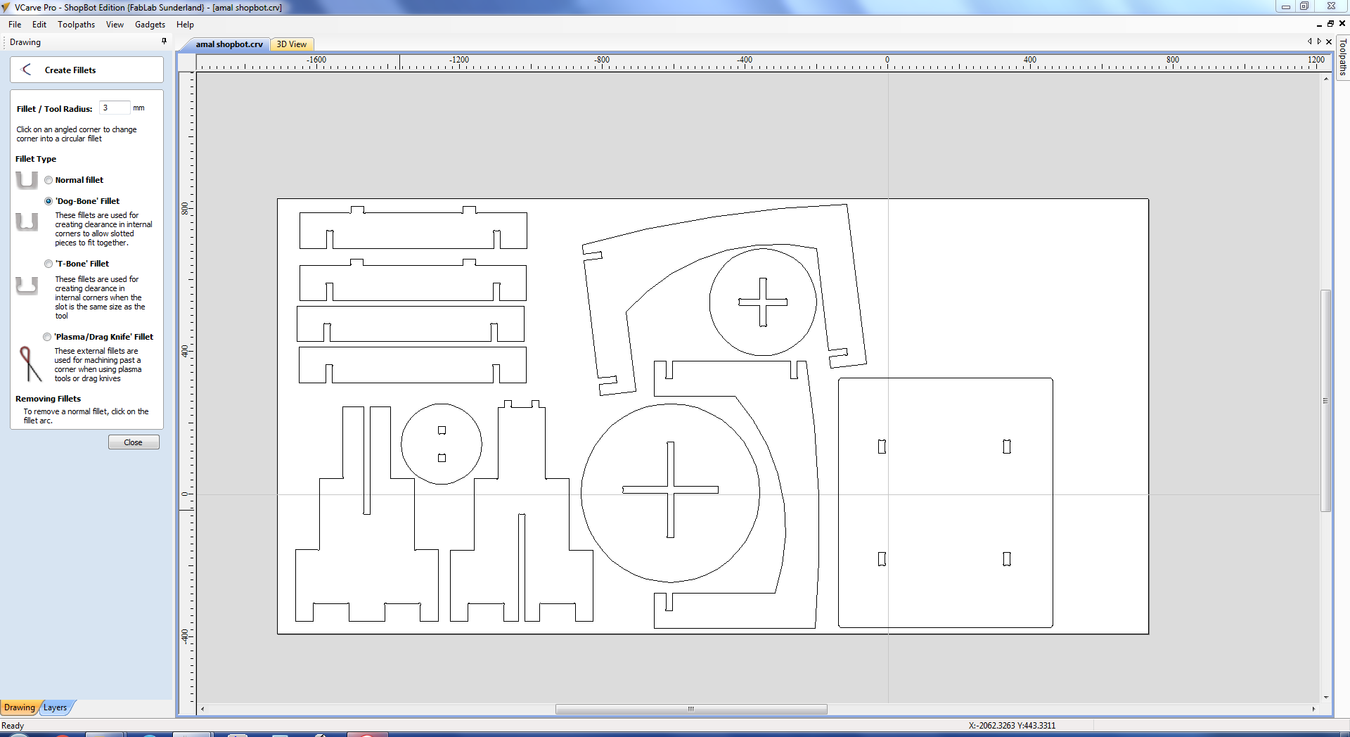
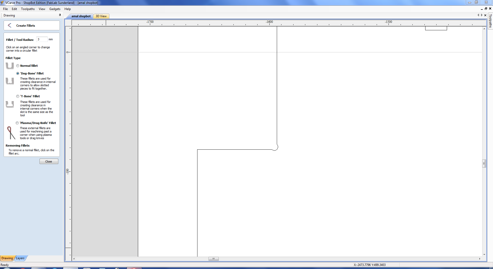
(vx)Then created the dog bone from the profile which is used as cutter compensation and added the tab for holding the material even after the cut.
(vix) After Exporting and arranging the dxf file the machine setting parameters were primarily explained by the instructor which comprises about
Selection of tool
1)Normally the tool consists of upcut,downcut and combined tool bit.
2)End of the tool bit is categorized into ballnose endmill,single flute,duo flute,etc
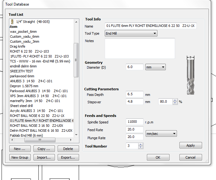
3)The basic diameter of the tool selected was 3mm and 6mm for cutting purpose.
The tool selected was 6mm upcut single flute
Selection of cut
1.Basically there are different types of cut namely pocket cut,profile cut etc.
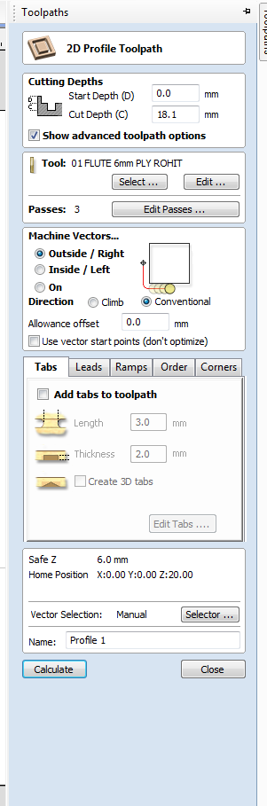
In that I have selected the profile Cut
2.Creation of profile was about tool path generation and for that we will have to define whether the tool must pass through the or inside or outside which depends on the priority of the material to be cut the profile and the
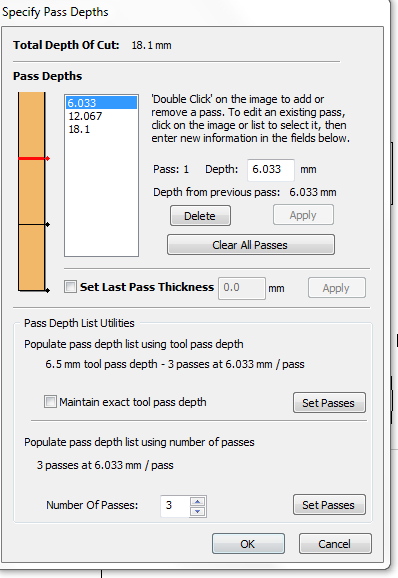
I have selected the depth as 18.1 mm as cut depth and selected 6.5 mm as per pass cut depth(it will automatically defines the cut as 3 pass)
3.Slection of pass by defining the cut depth was estimated.ie.we can select the number of passes of tool bit which requires for the perfect cut without breaking the tool bit.
4.After that the selection was done to define the cutting order i.e. we will have to select the order of cutting without disturbing the cutting and the materials should not move after the cut is passby.
I selected the inner cuts to cut first as profile 1 and the rest of the outsider cut as profile as the order of cutting
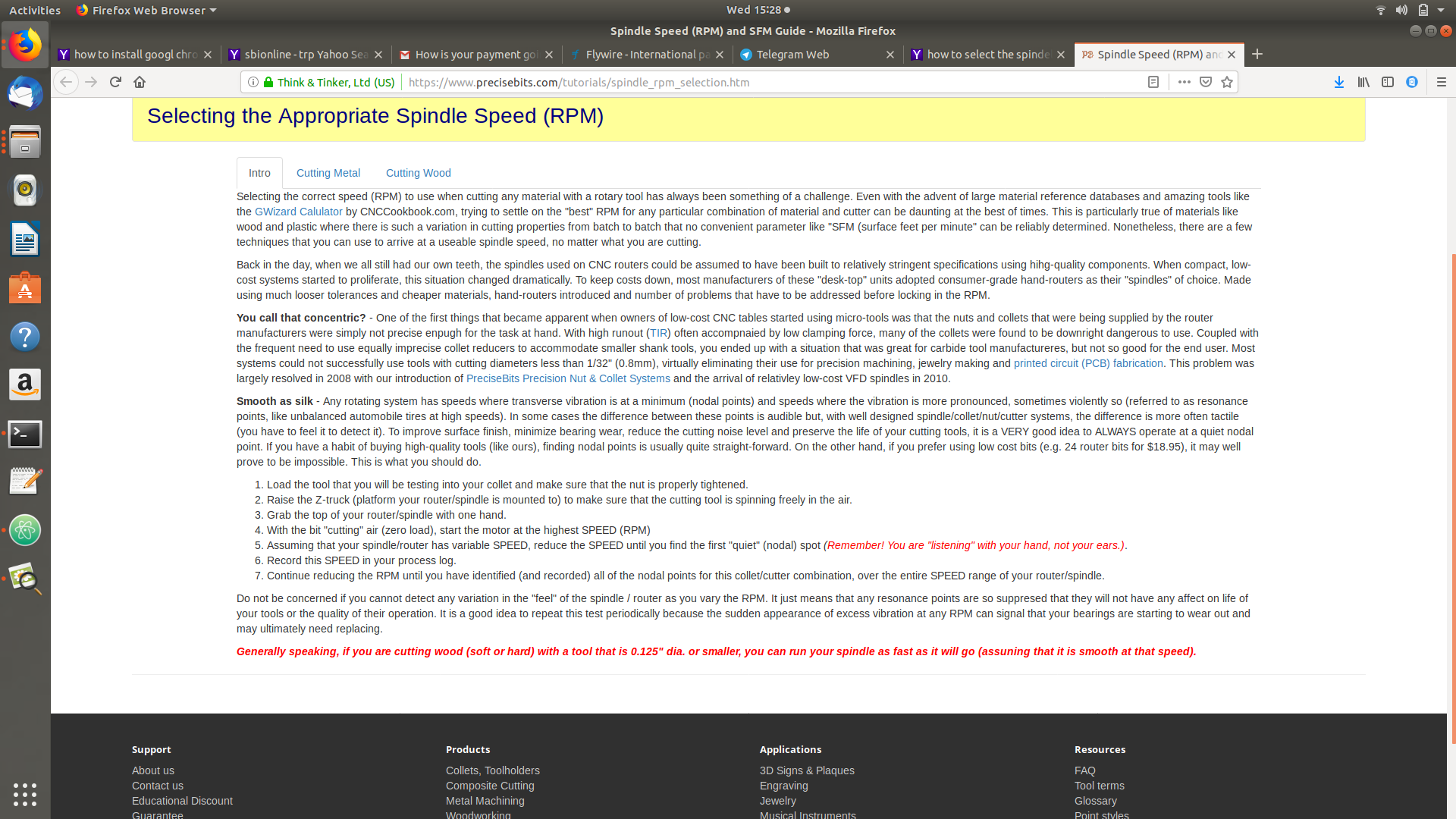
5.Then selected the spindle speed and 11000rpm for cut which was pre defined earlier by the lab but the instructor guide to refer somewhere in internet or mechanical data book.
I referred the precise BITS site for reference
6.Then the files file is been saved to .sbp
Onto SHOPBOT
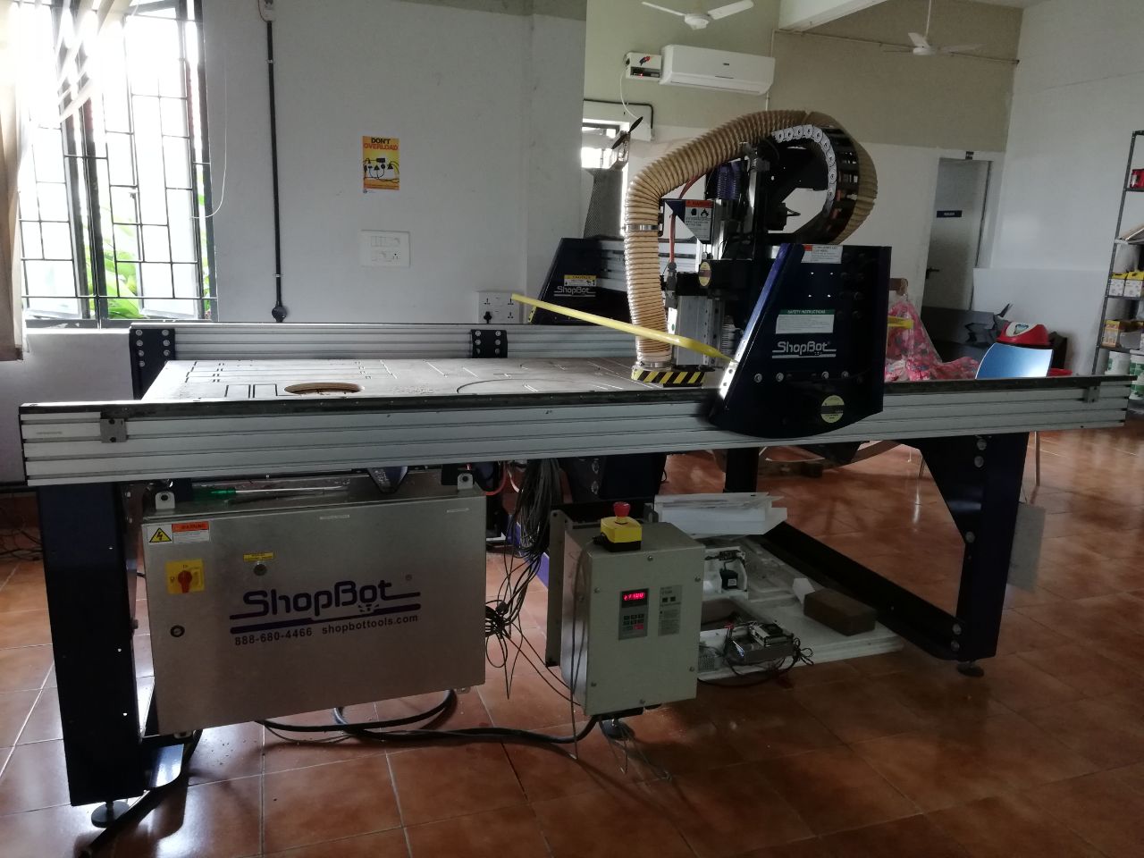
1.Trivandrum fab was equipped with 8*4 bed size shopbot cnc which is manufactured in the USA.
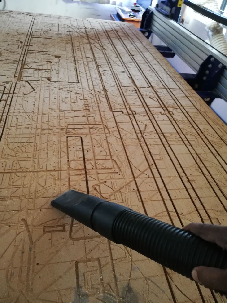
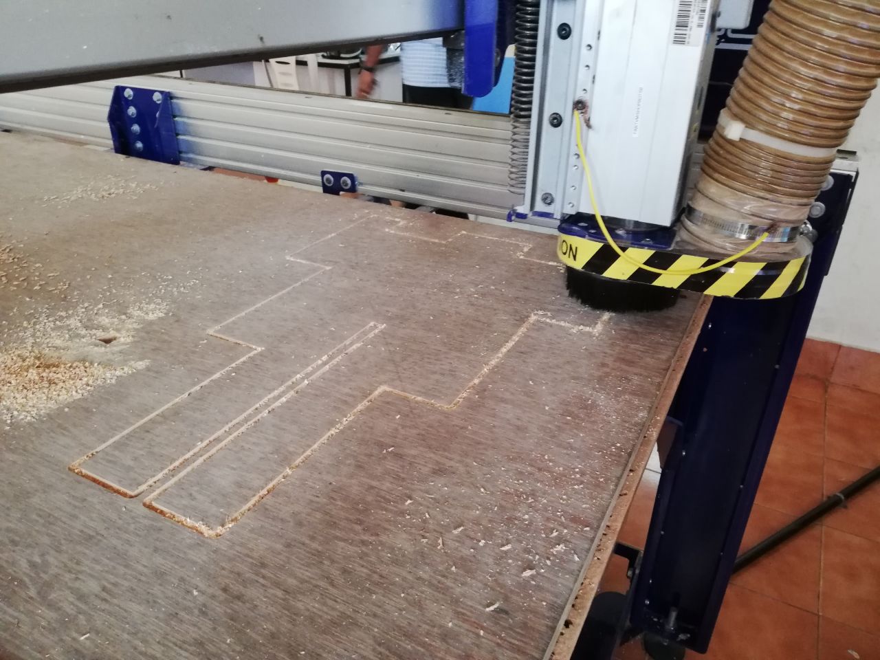
2.The first thing I did was to clean the bed using a vacuum pump.
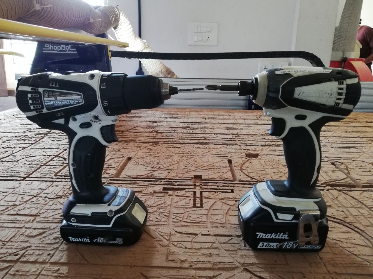
3.Then Fixed the 8*4 marine plywood in the bed and fixed it using screws by the help of makita drilling machine.
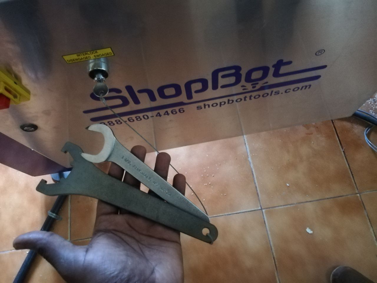
4.Then I Fixed the tool bit which was 6mm upcut single flute tool bit and for that i used the spanner kit which was affixed by a key in the shopbot itself.
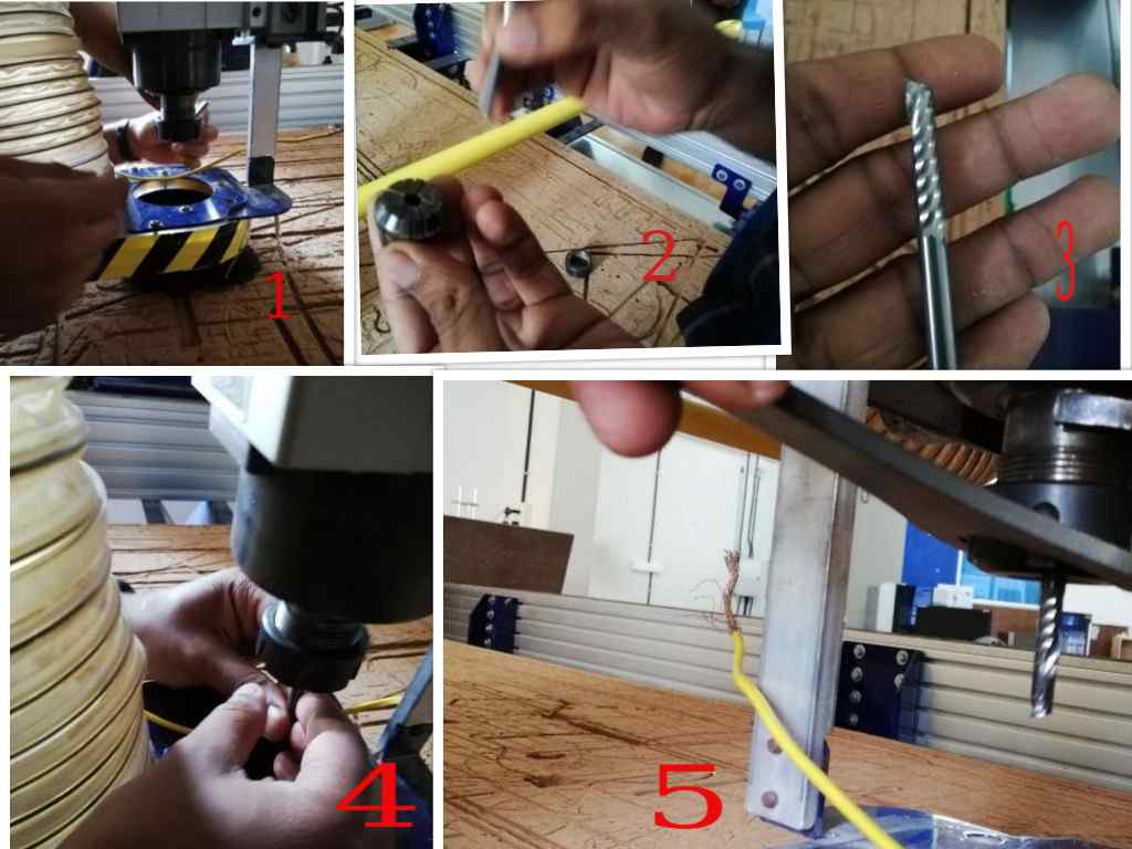
5.Then Turned on the Shopbot for 2 mins with spindle on for self lubrication purpose and the given for cutting and the estimated job required about 1.7 hours and the better part was I combined the work with my colleague Manu mohan so that we can cut both the design in single sheet of plywood so that we could save time and material.

6.Then I fixed the XY axis which is away from the nail in the bed and then fixed the Z axis by calibrating it with a plate in the machine itself.
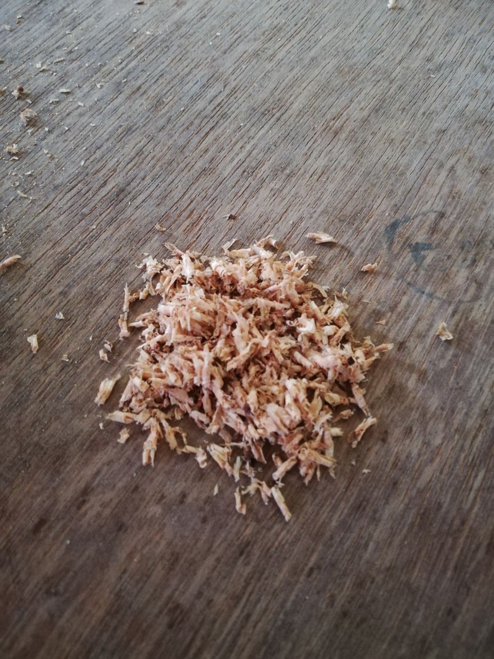
After that the instructor advised to check for the cut chip to ensure the cut is fine.
The Assembly was bit challenge and it succeed.
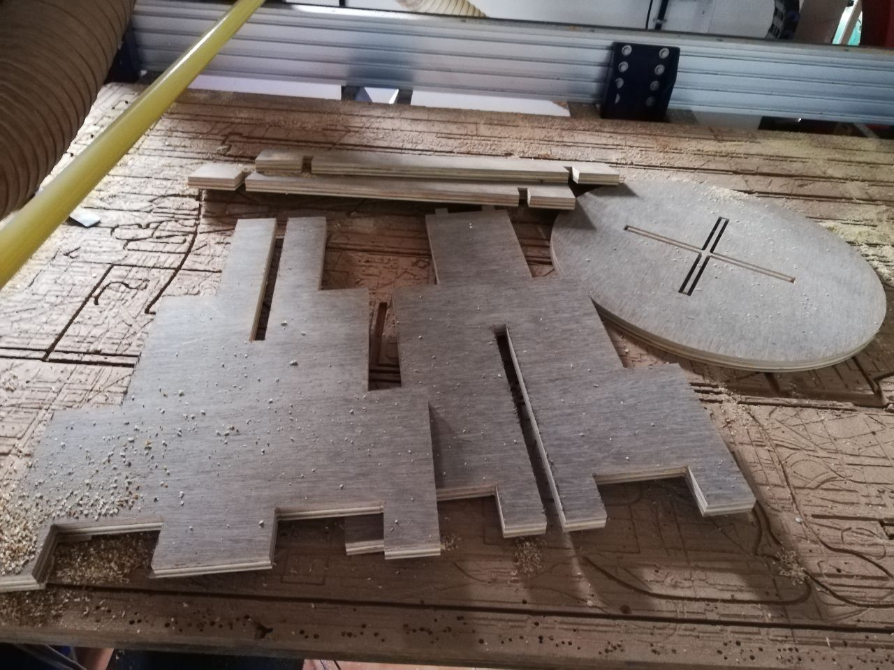
7.AFter Cutting the parts I assembled it but the material fits was little tight.So I planned to file using a chisel and made it correct as if I can fit the joints bit easy but tight.
CLICK HERE TO OPEN.
files
Click here to download the file
Click here to download the V-Crav file