4. Computer controlled cutting
OBJECTIVE
The main objectives of this week was.
1.To do something with vinyl cutter.
2.To construct a 2D parametric drawing in order to create a multipurpose design.
3.To study the features of laser cutting machine.
Working with vinyl cutter
The first question that came to my mind while using vinyl cutter is Why this machine is in FAB LAB.
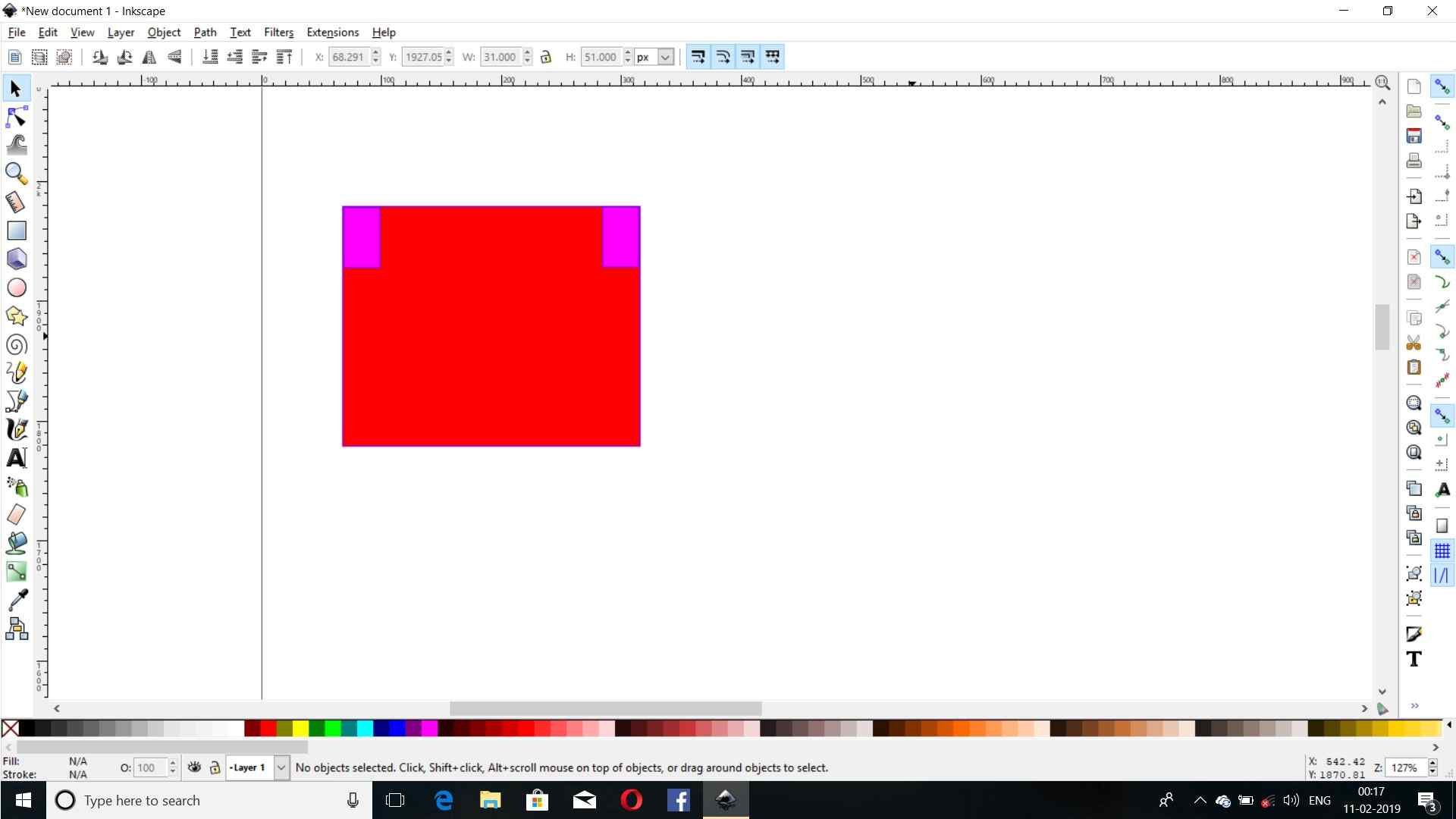
Later I went through the designing process by using the “Inkscape” and did some operations like:
1.Downloading a raster image and converting it into a vector image by using “Bitmap trace”.
2.Then I corrected the dpi and edge detection and brightness etc.
3.Then I exported the “SVG” file into a “png” file.
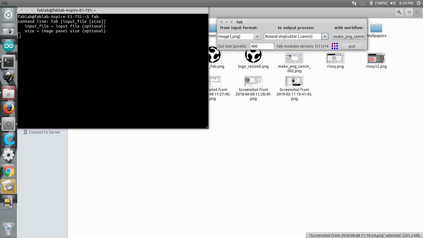
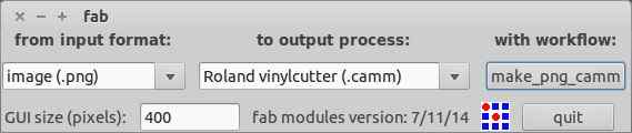
4.By using the terminal I opened “fab”option I launched the driver software.
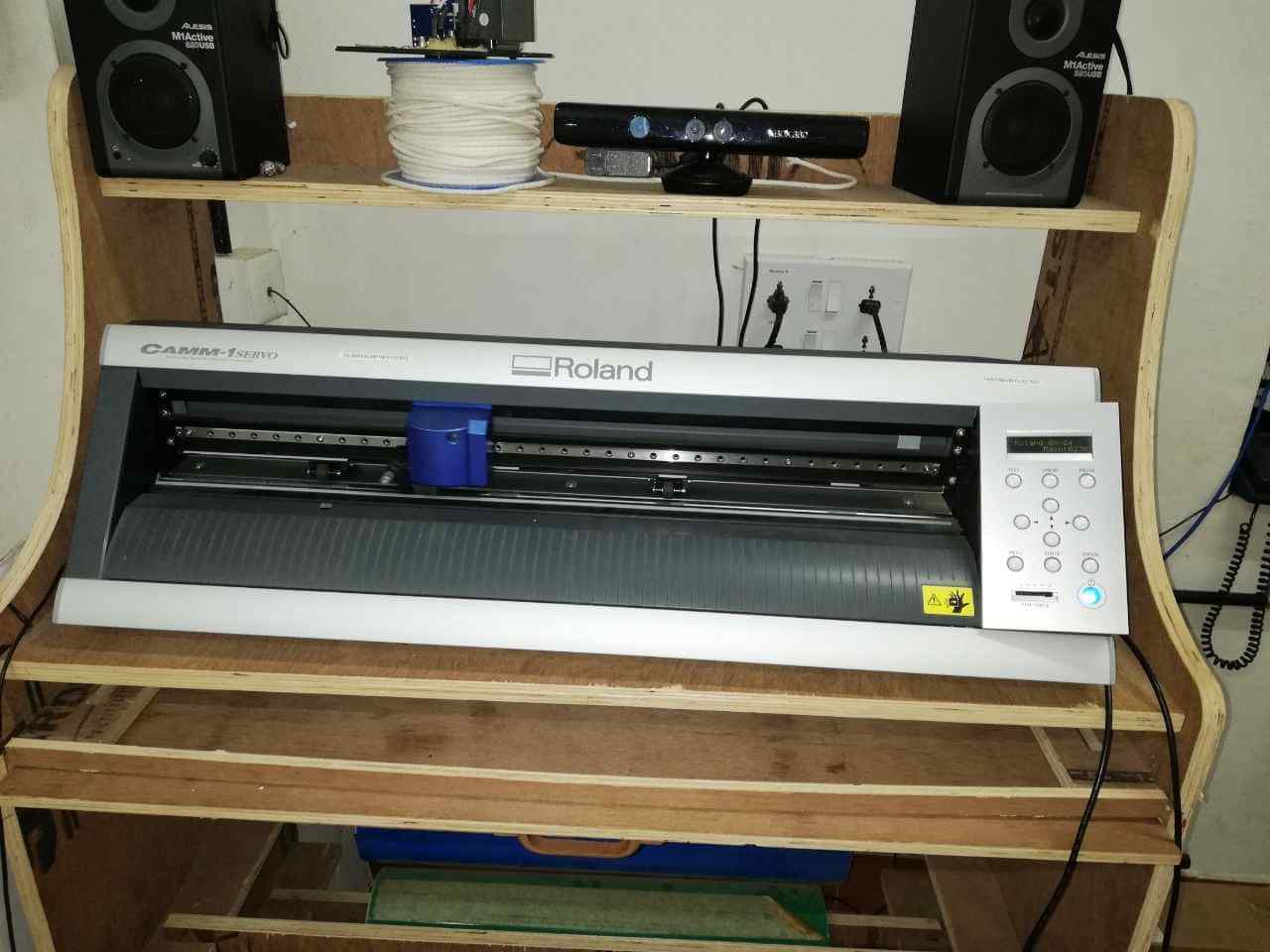
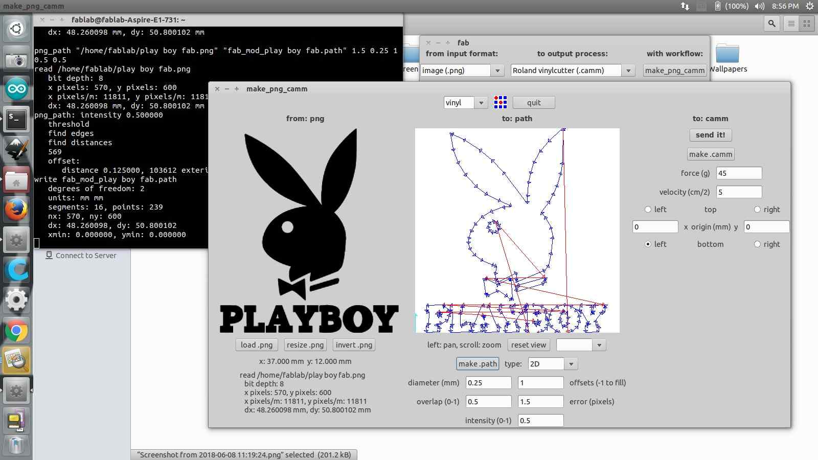
5.Then I loaded the image and traced the cutting path and send the file to ROLAND CAMM.
6.I machine I corrected the pen force,loaded the vinyl piece and the origin was set and the operation was started by using the send option.
7.After cutting the image ,I removed the cut part from the sheet by using a masking tape and it was corrected by using the help of tweezers.
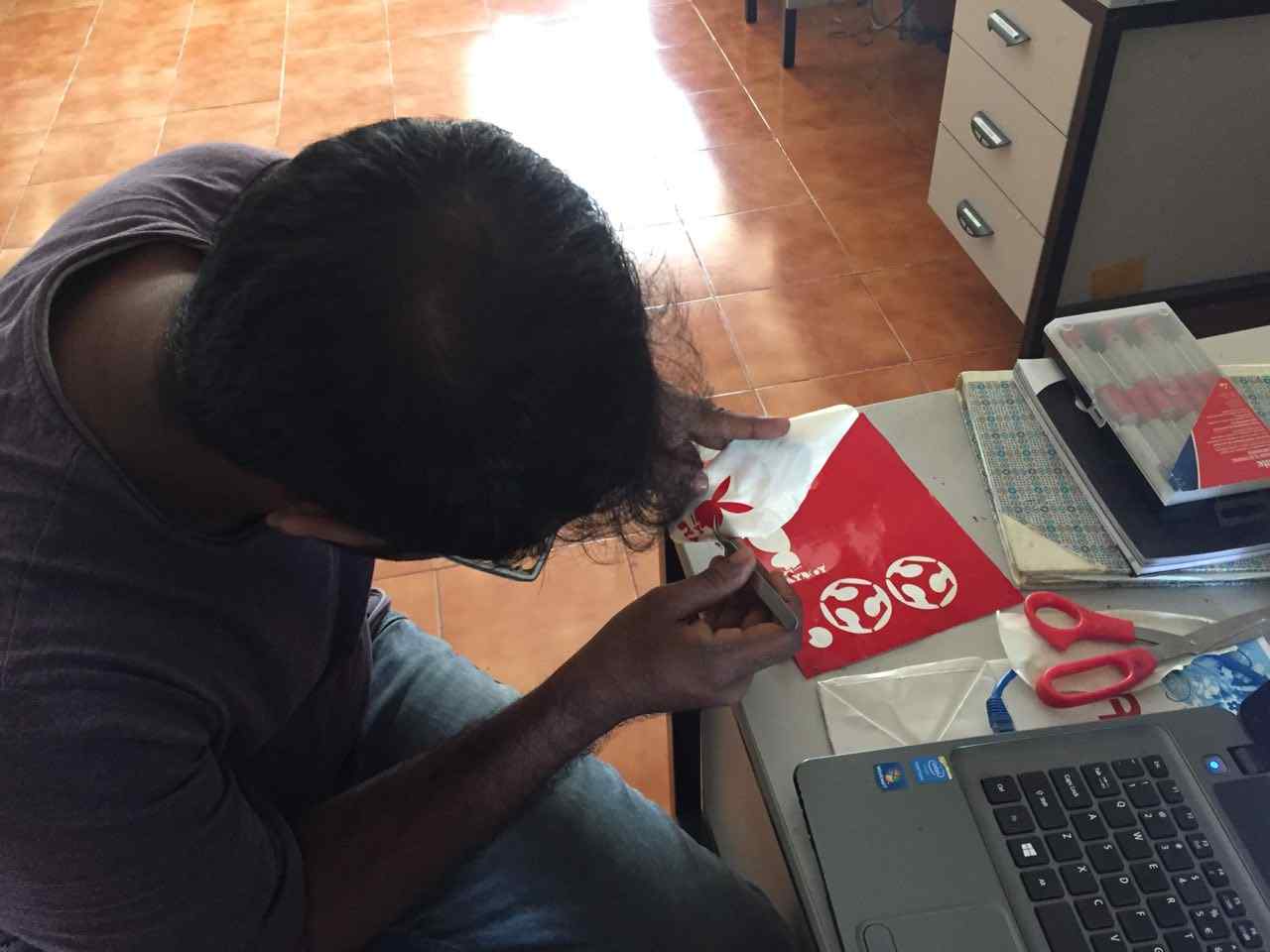
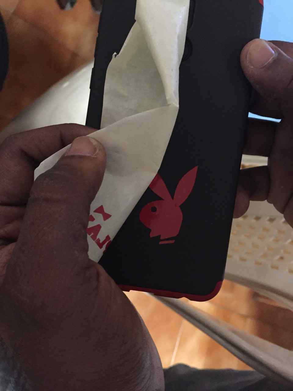
8.After the operation i pasted the image to back side of my cell phone.

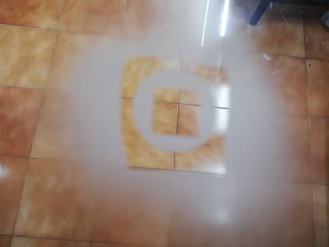
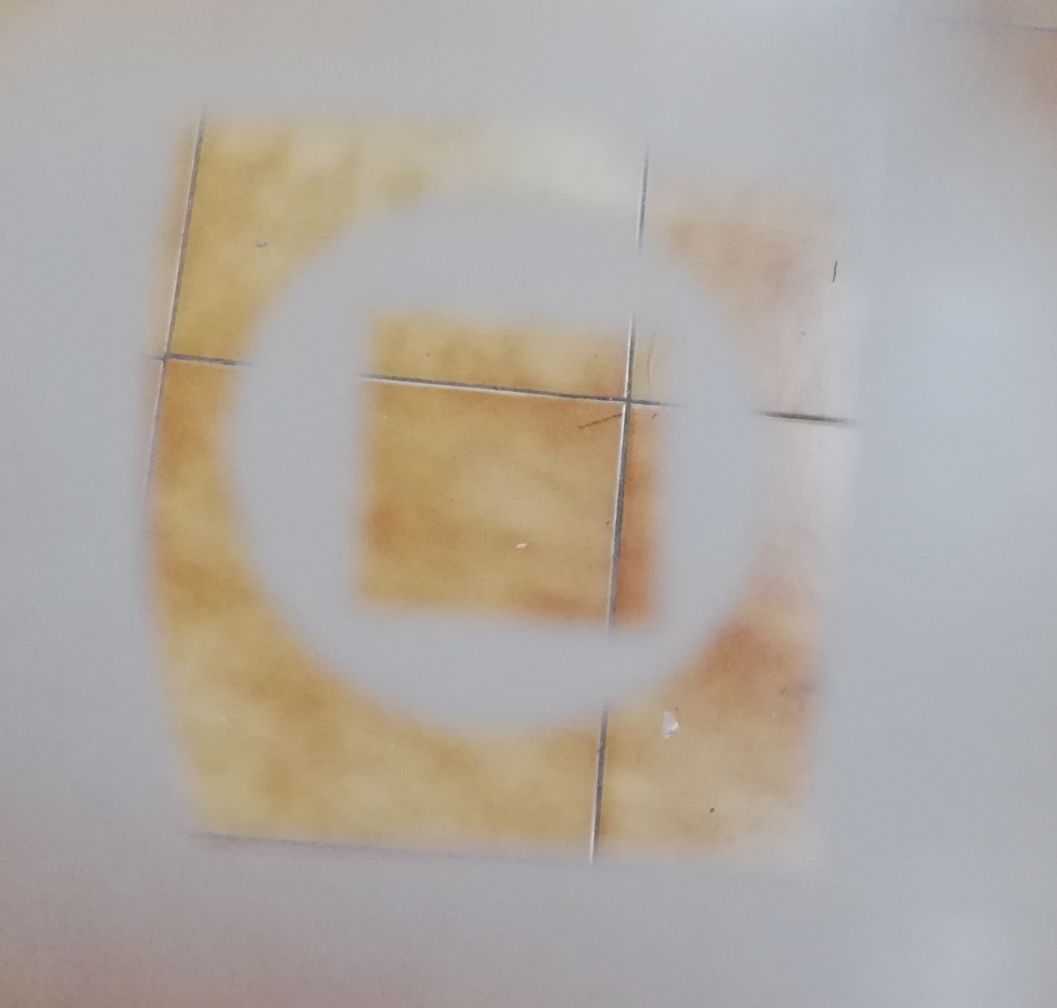
9.Then I tried a test figure to imprint on a transparent acrylic using sand blaster by affixing the negative part of the vinyl to it.
Working with Laser cutter
The major objective was to create a model of a “multipurpose joint” using parametric fits
Initially I tried to do it in Inkscape and I felt it like a bad move because I can’t fix the parameters and proper dimension
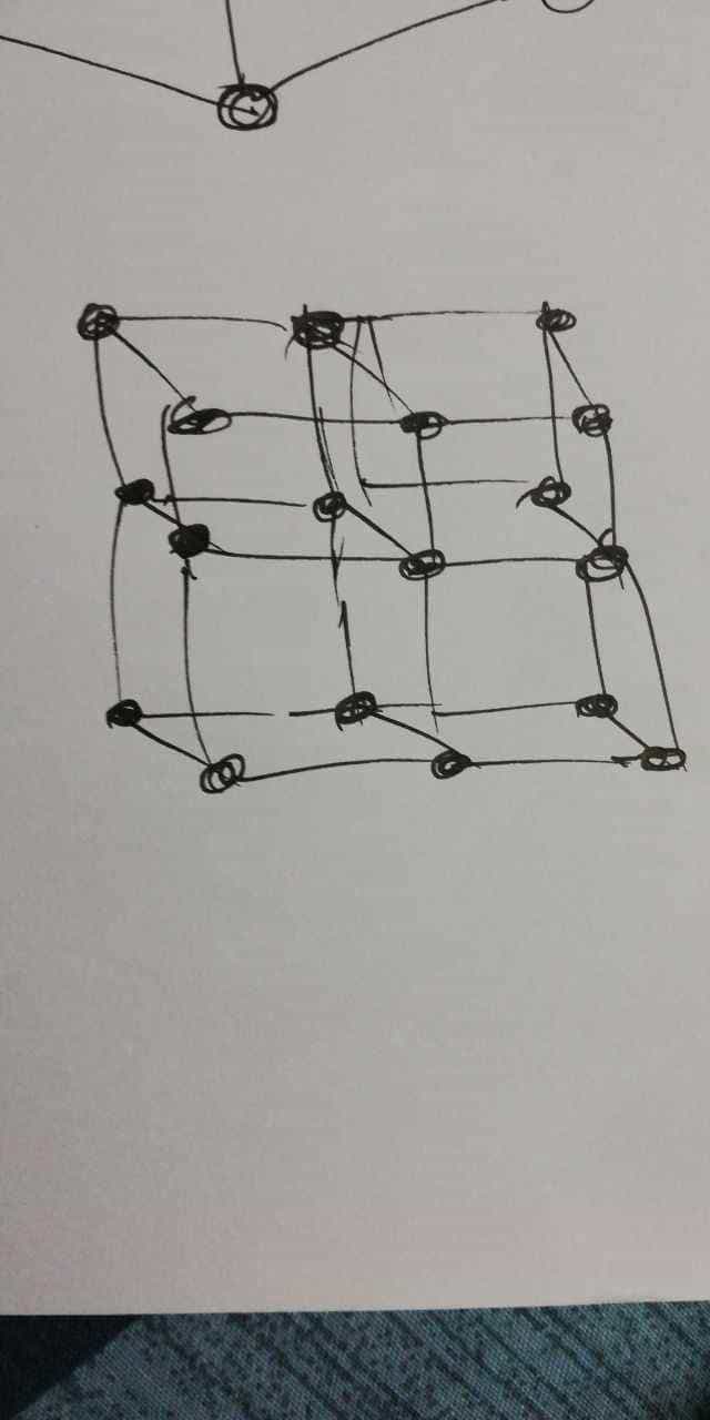
Then I planned to make a handmade model using forex sheet to identify the dimensions but the scales were not right and I didnt get perfect measurement and I planned to do it in 4mm cardboard.
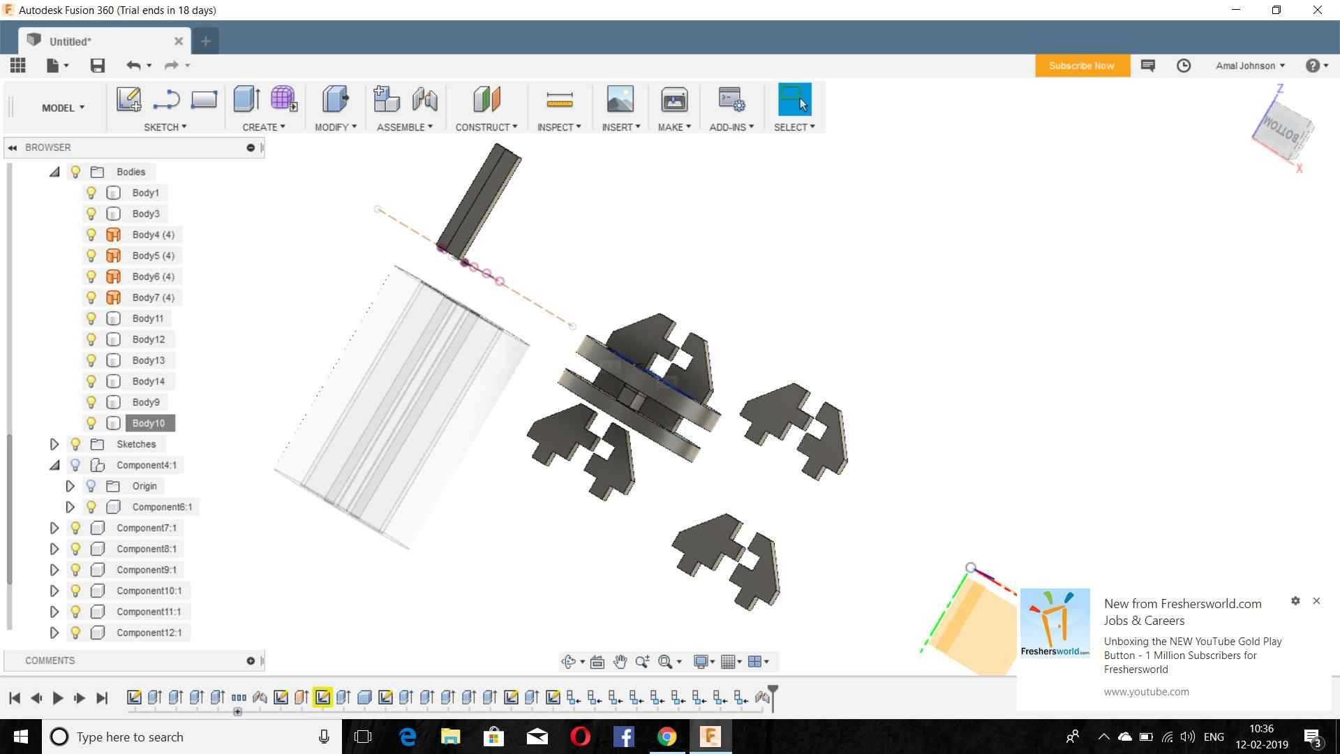
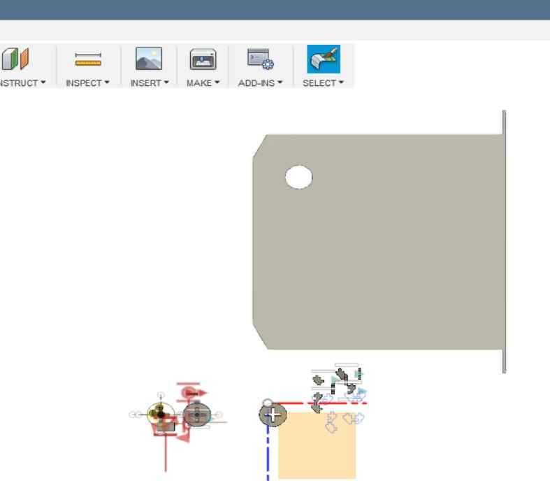
After obtaining the dimensions of the image i started working in “Autodesk Fusion 360”
Since I was a beginner in Fusion I felt lots of problems like fixing the parameters,dimensions etc..
The part diagram also went wrong because i entered a wrong parameter.
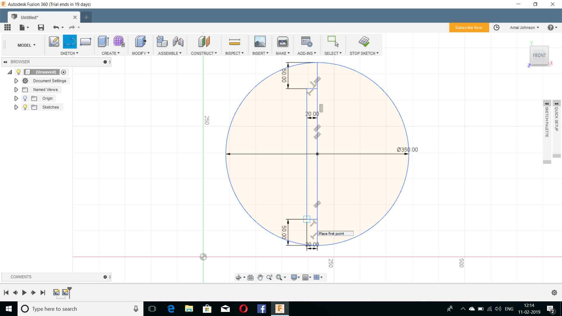
Then I drawn the base circle with the parametres naming as thickness,circle dia,etc.
Then I planned out to construct whole design by using Fusion 360 and the results are pinned down
While working on i faced difficulty in selection of planes.
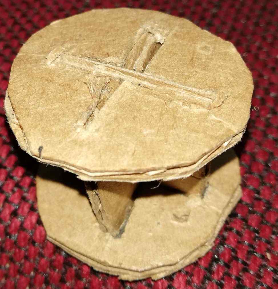
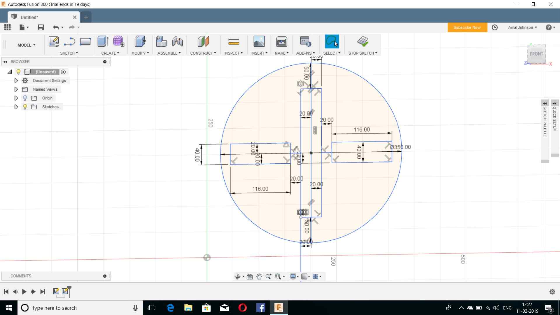
Then I created a sketch of base circle with the joint and fits on it and after that I extruded the file.
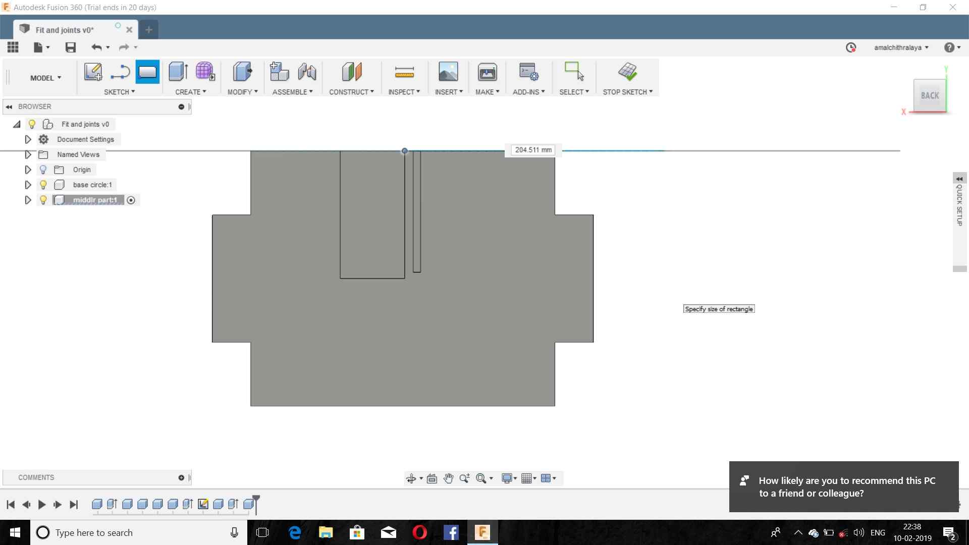
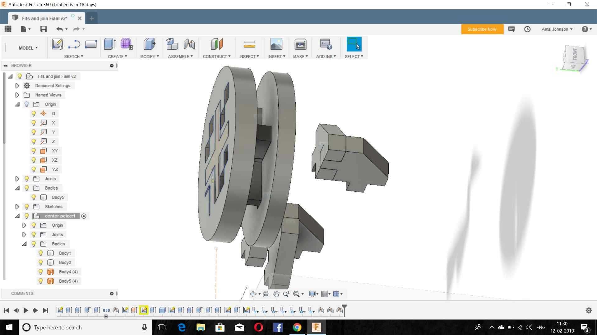
The Created the 10mm Thickness for that and jointed the base circle using assemble->Join option and this was done in order to check the fit consistency.
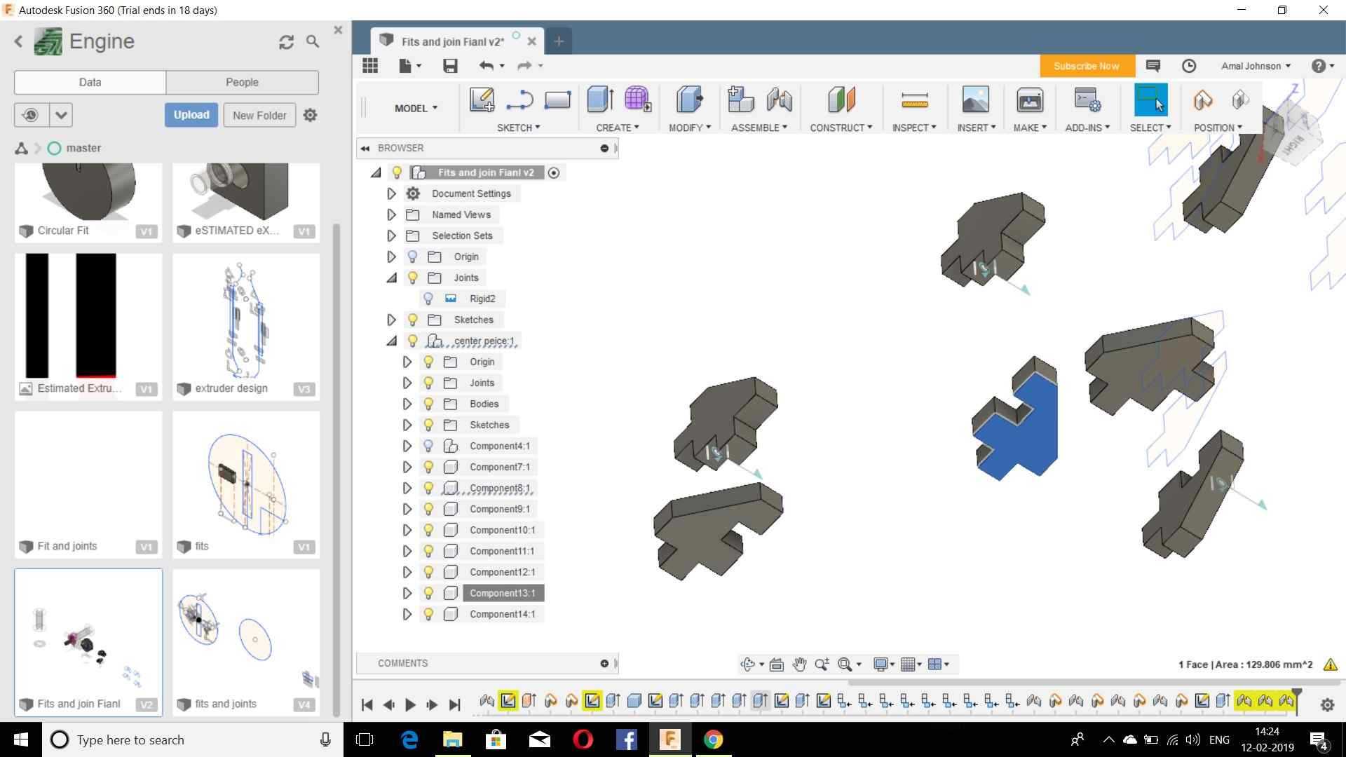
I repeated the similar process for making the bance parts and I Created the parameters like Thickness,Circle,Rectangle,etc.
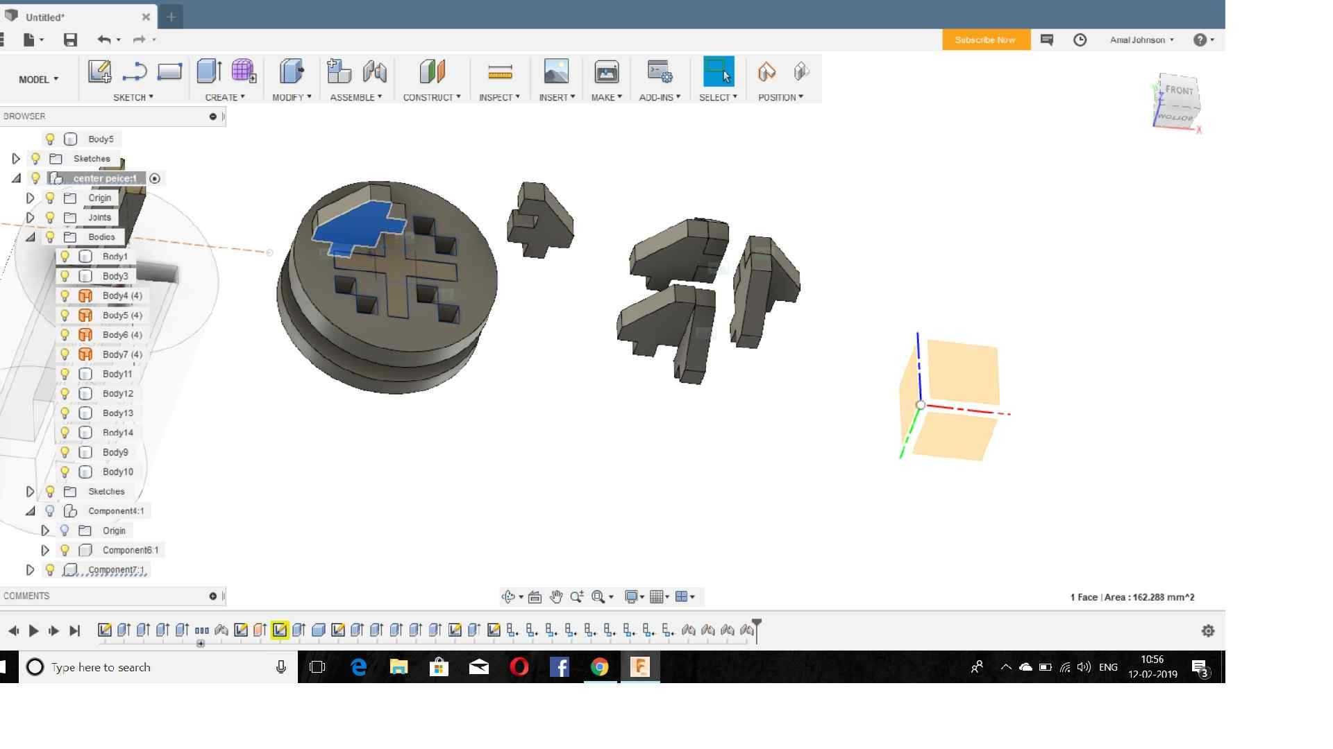
The jointed all the parts to check the clearance of the fit.
Then a problem occurred with the disassembly and found out a solution from youtube and from that I learned to create a “Finger fits”.
Then I saved all the parts to IEGS format and then the parts to DXF File.
But the laser cutting machine was at servicing stage and I couldn’t complete it
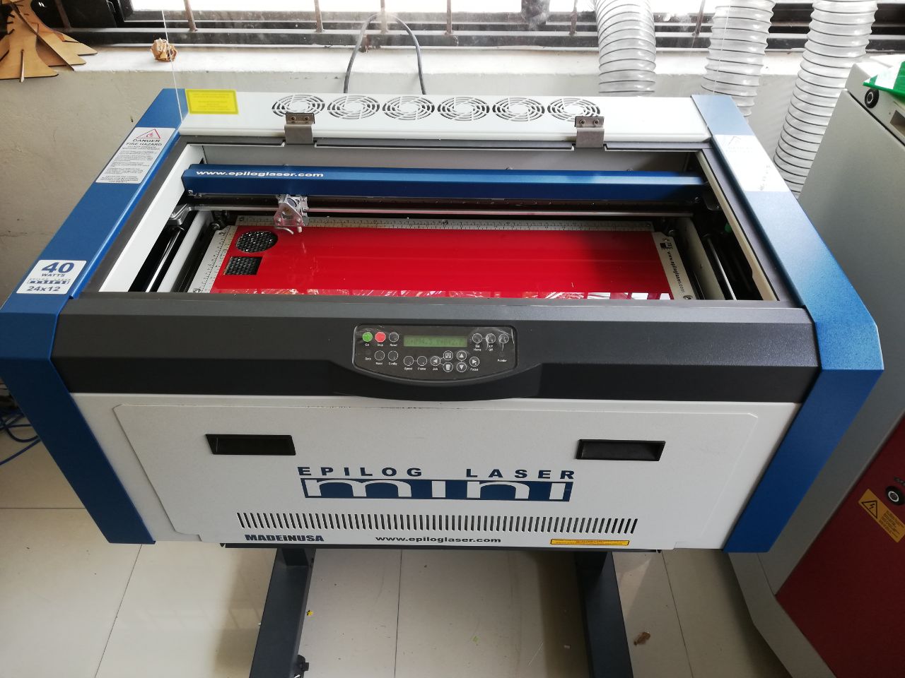
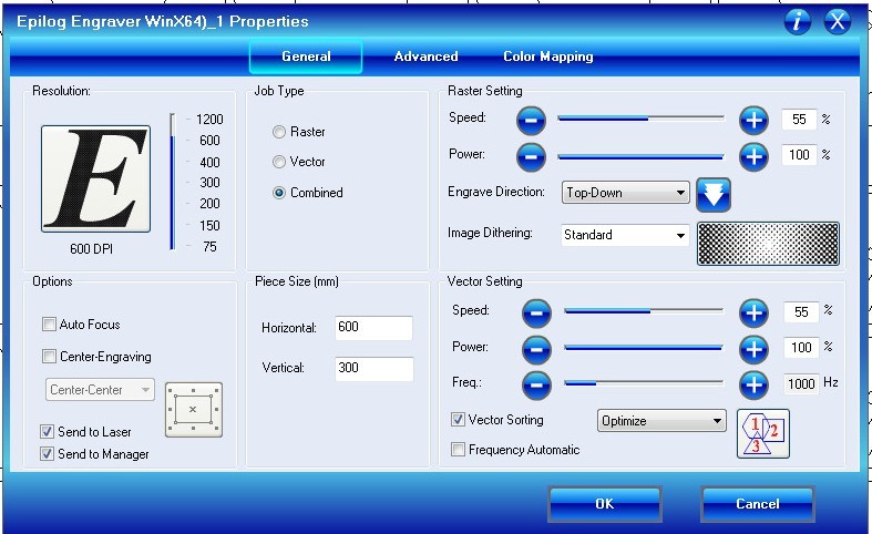
After that another machine was installed and that was epilog mini 40 watts.
When I tried to cut the estimated design I found that it was wrongly design because the parameters given to it was completely wrong and I couldn’t finish the cutting.
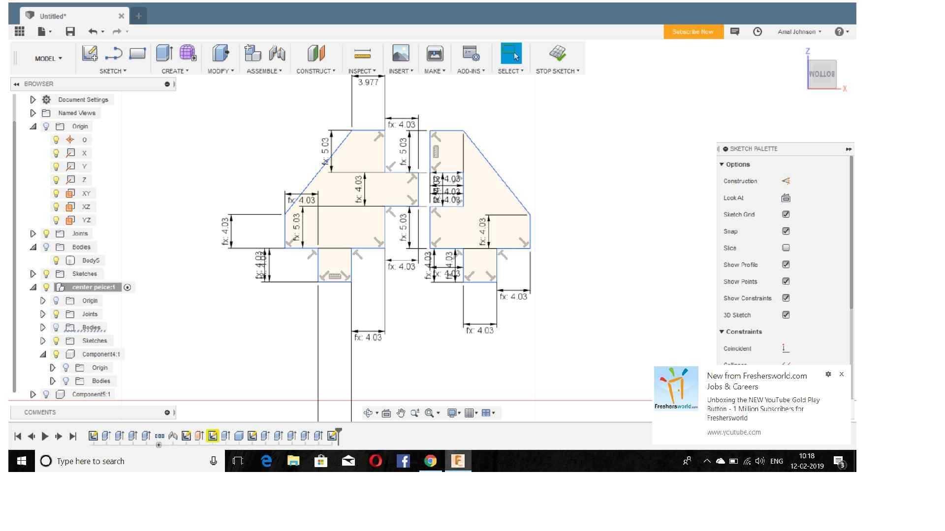
Then I re-drawn another design which can be transferred to another design by using simple shape in fusion 360.
This time I was very cautious about the design parametrics
The very first thing I did was to set X,Y and Z directions

For setting Z direction manually ,the machine got a ‘V’ Shaped pin and its tip should touch at the cutting piece and by that the laser will focus the Z axis.
Group Assignment
The very next thing was the group project.The task was to find the kerf of different materials like cardboard,Acrylic etc.
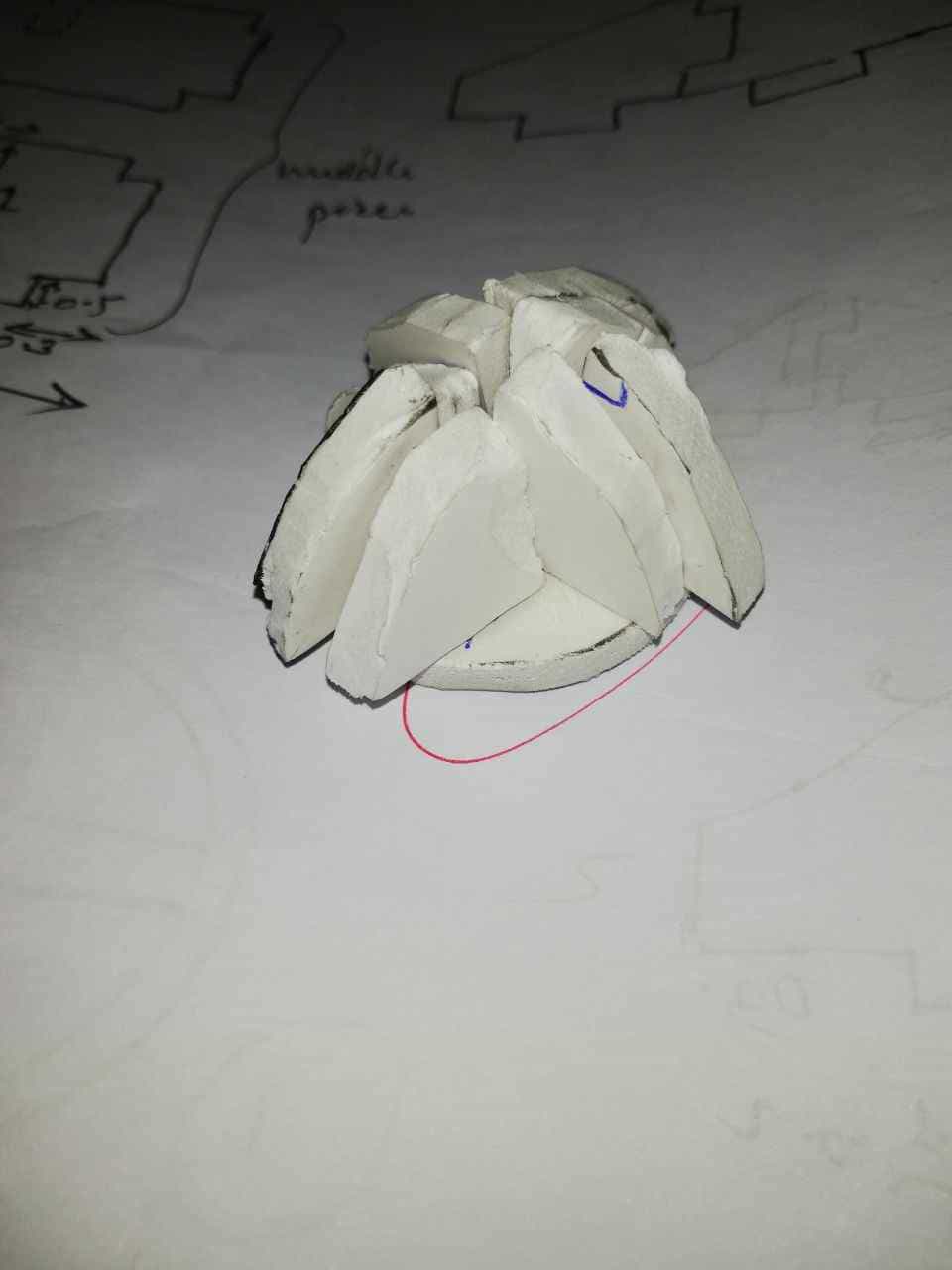
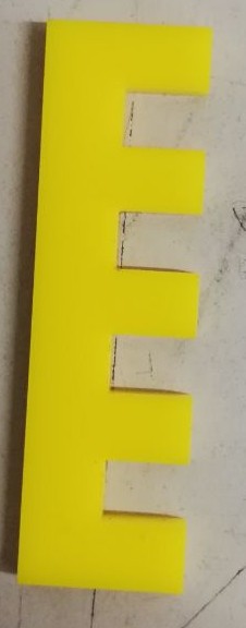
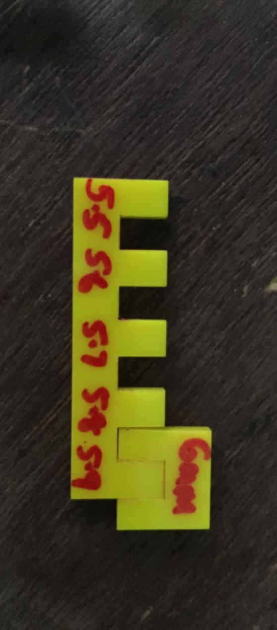
This shape was made with 0.1 mm difference in 5 mm cut to identify the fit and its understood that the approximate fit is about 0.5 mm difference from the actual dimensions i.e 0.5X 2=1 mm
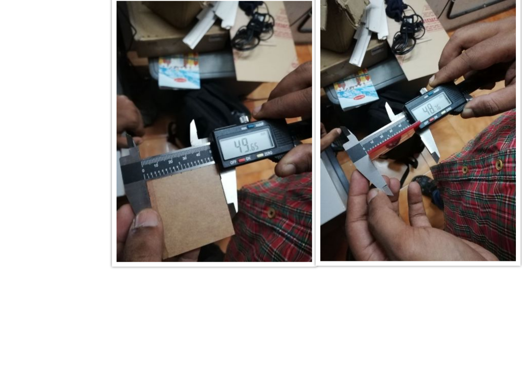
For understanding the kerf We made a Square of 5cm and cut made the cut.After that we measured it with Vernier and found out that the kerf for cardboard is 0.05 X 2 and for acrylic it is 0.1 X 2
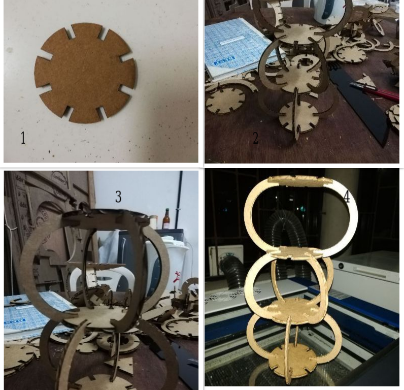
This design was able to transform different sculptures and with this I even made a double floored structures.