15. Mechanical design
This week we have to build a device in group. But the work of each participant should be autonomous…
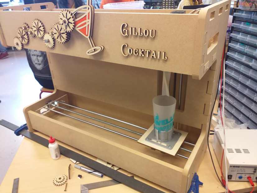
We had decided to work on a cocktail robot : a device that distribute a certain amount of different liquids and a mixer.
The cocktail robot is severals part :
-
an axis that move the glass from one part of the device to each element.
-
several peristatic pump, will suck the liquid and pour into the glass.
-
a mixer will go down into the glass to mix .
I decided to build the mixer part.
Mixer
The mixer has to move up and down, it’s a kind of Z axis. On the moving part a motor turn an helical form like a blender/mixer. With the group we discuss about the constrains. As it is a Z axis with a certain length, the torque should be minnimize that mean the lenght between the rail and the mixer should be minimize. So I have to have the dimension of the other axis and be as close as possible to it.
But as it is a group work, every one need to work and some decision can not be made from the start. So I decided to build small part that can be placed later at the correct position.
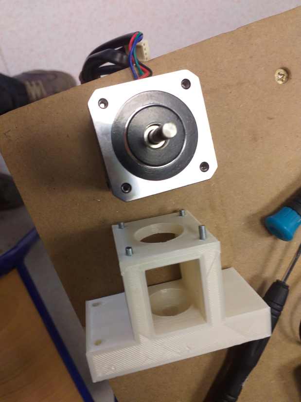
I had also to take in account the available material at FabLab Sorbonne, like the lenght of the shaft and the length of the threaded shaft, the size of the motor coupler, the motor size …
I begin to search for the available material and check the dimensions and that everything fit together.
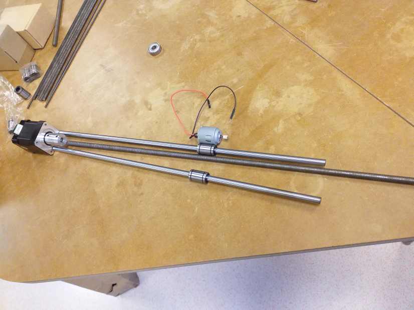
I slide the differents elements. I screw the coupler and rotate the threaded shaft manually.
Draft design
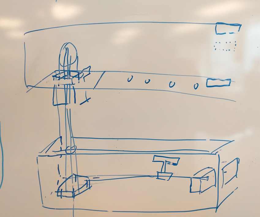
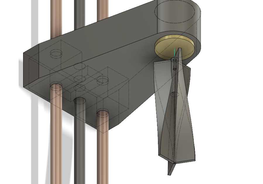
I made a draft design on Fusion to show and disscuss with the rest of the group. All the dimensions are parametrics because I did not had the chance to measure all the dimensions.
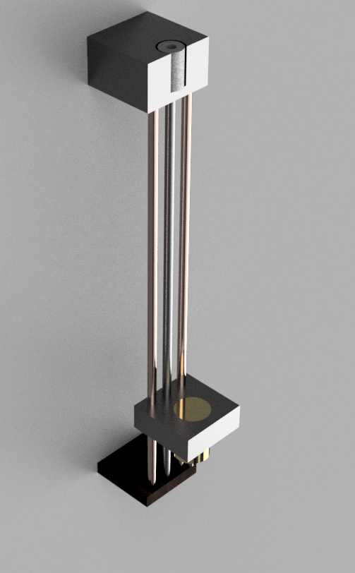
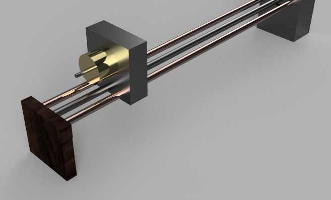
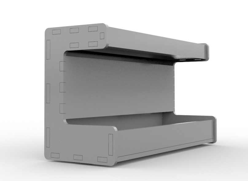
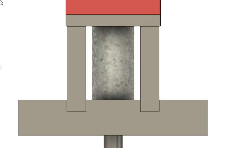
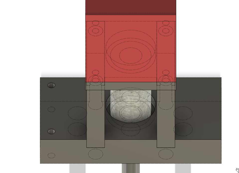
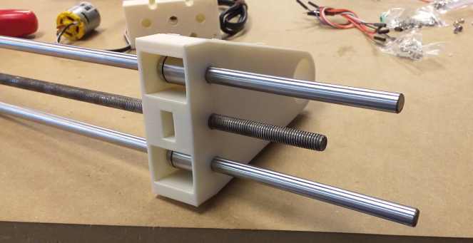
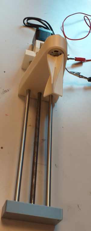
A lower part hold the 2 shafts and support but let turn freely the threaded shaft at a precise position. An upper part, hold also the 2 shaft in place but the threaded shaft is connected to the motor coupler. The moving part slide on the shaft with 2 linear bearings and a nut is sliding on the threaded shaft , this part is big and hold also the mixer motor.
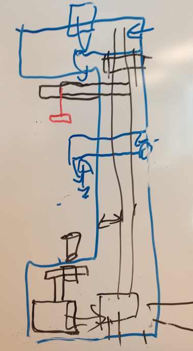
Group sketch draft
Leo has also made a first version of the enclosure that will be the structural part.

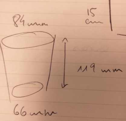
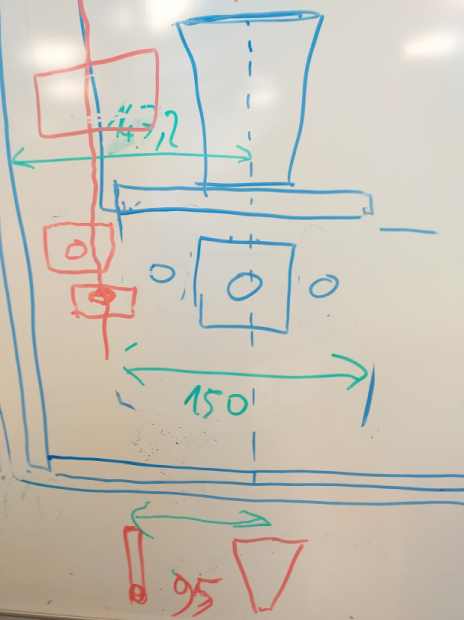
We regroup our first sketches and draw on a board to see more clearly the differents constrains.
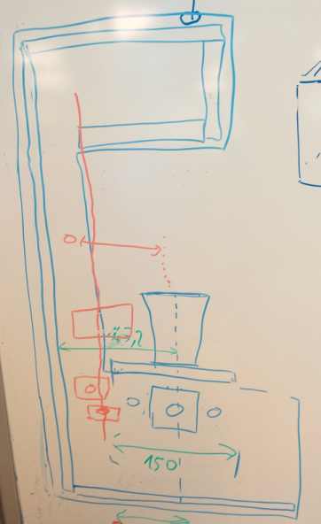
Finally I get the size of the glass and the size of the horizontal axis.
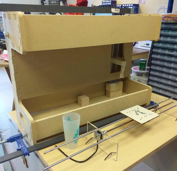
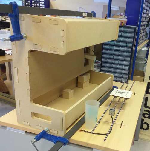
Cardboard model
Then Léo built a cardboard model at 1:1 scale to have a better idea of how to fit and the real size.
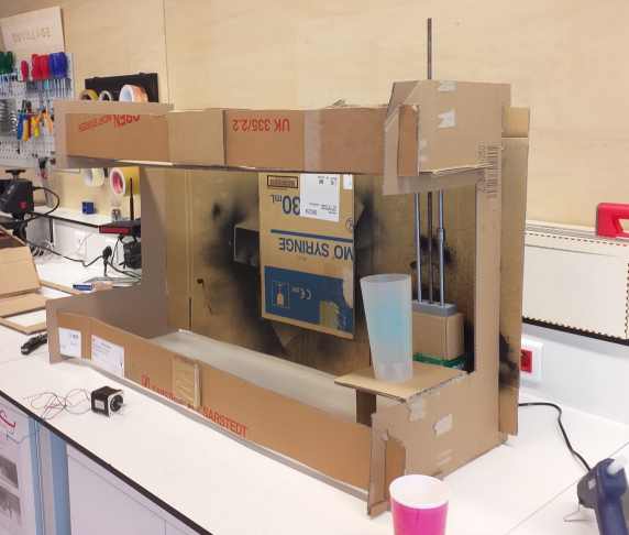
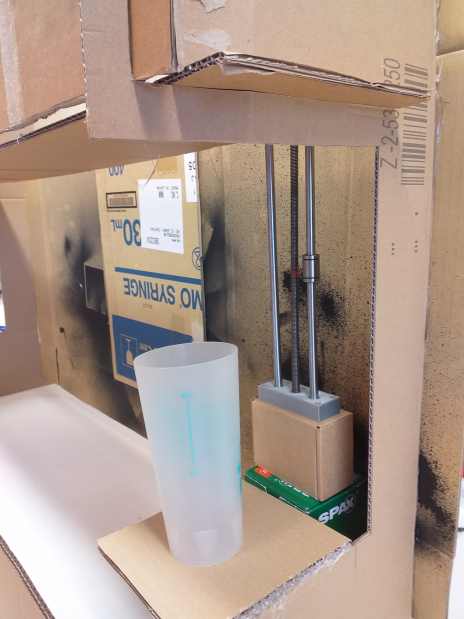
In the mean time, I had printed the first part and put them in the cardboard prototype.
Model
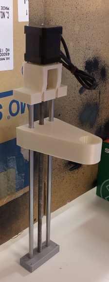
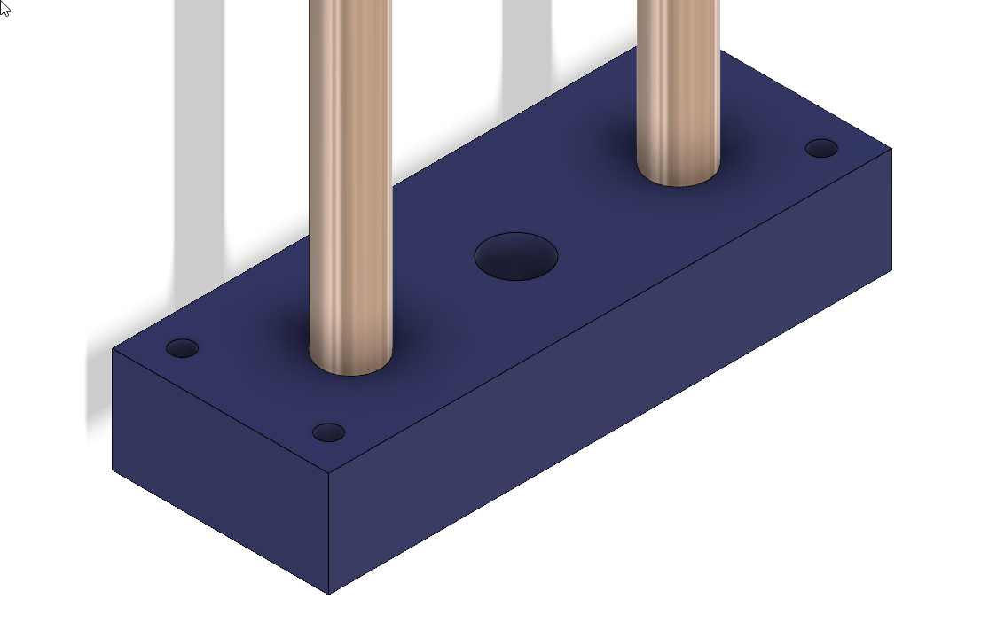
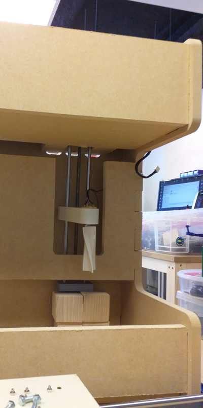
The bottom fixation hold the 2 shafts and support but let turn the threaded shaft at a precise position. 4 holes are screw to the external case.
For the top fixation, I need to place the motor coupler and the adjusting screw should remain accessible , I also need to screw the nema motor to that part from the bottom, so I build some kind of tunnel to have access from the other side.
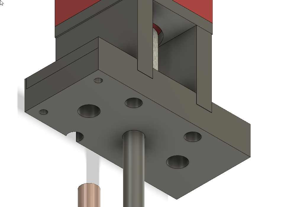
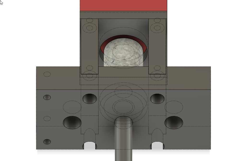
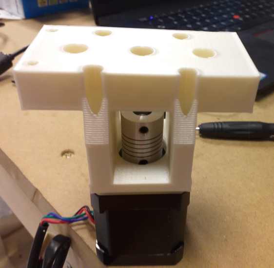
As you can see, the adjusting screw are accessible.
The moving part slide on the shaft with 2 linear bearings and a nut is sliding on the threaded shaft , this part is big and hold also the mixer motor.
With the 2 linear bearings .
The result with the motor and the mixer.
Moving part
Connected directly to a DC power.
The helical form is slightly off centered here , this is corrected later : Take a look at the video at the end of this page.
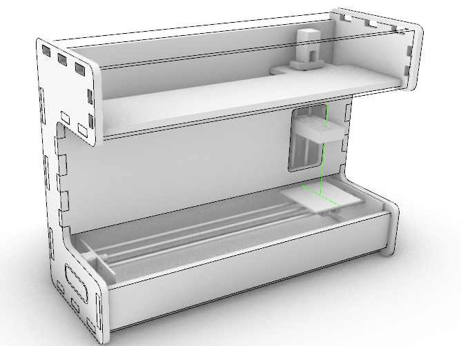
In the frame in construction
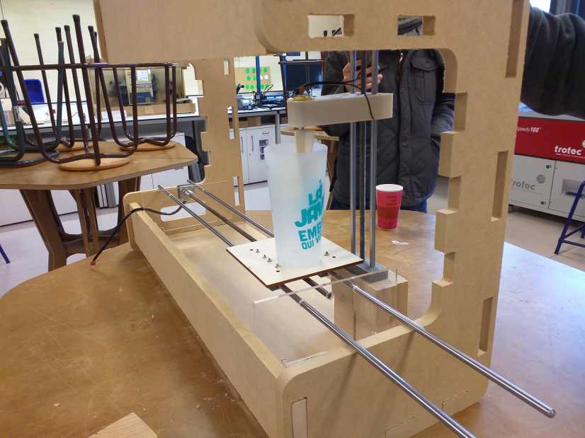
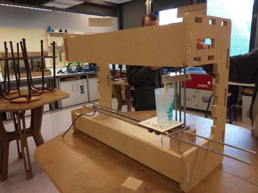
Several picture at differents steps of the frame construction.
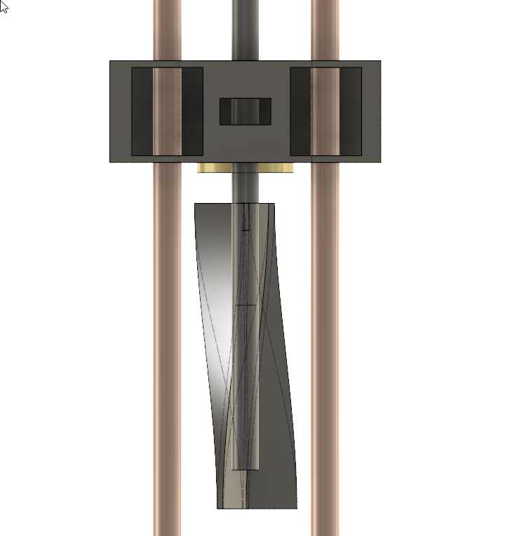
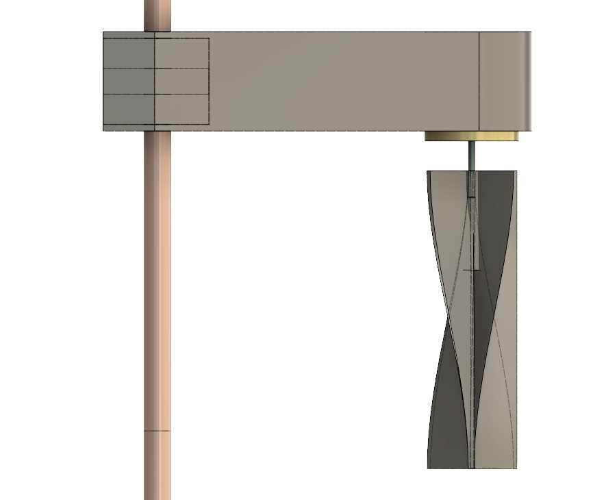
And one of the last 3d model with all parts .
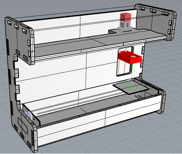
Almost finish
Electronic will be made in 2 weeks .
Other components
For the other component, you are welcome to take a look at my fellow team students :
-
Stéphane Muller https://fabacademy.org/2019/labs/sorbonne/students/stephane-muller/week15.html
-
Madjid AIT SI AMER https://fabacademy.org/2019/labs/sorbonne/students/ait-siamermadjid/assignments/
-
Leo Lhermitte https://fabacademy.org/2019/labs/sorbonne/students/leo-lhermitte/week_15.html
-
Julie Garnier https://fabacademy.org/2019/labs/sorbonne/students/julie-garnier/week15.html
Files
All the STL files : stl.zip
The fusion file : Z-mixerv22.f3d and the STEP conversion : Z-mixerv22.step